C150-E009-07EN
M3096EX AND M3096GX
IMAGE SCANNER
OPERATOR’S GUIDE
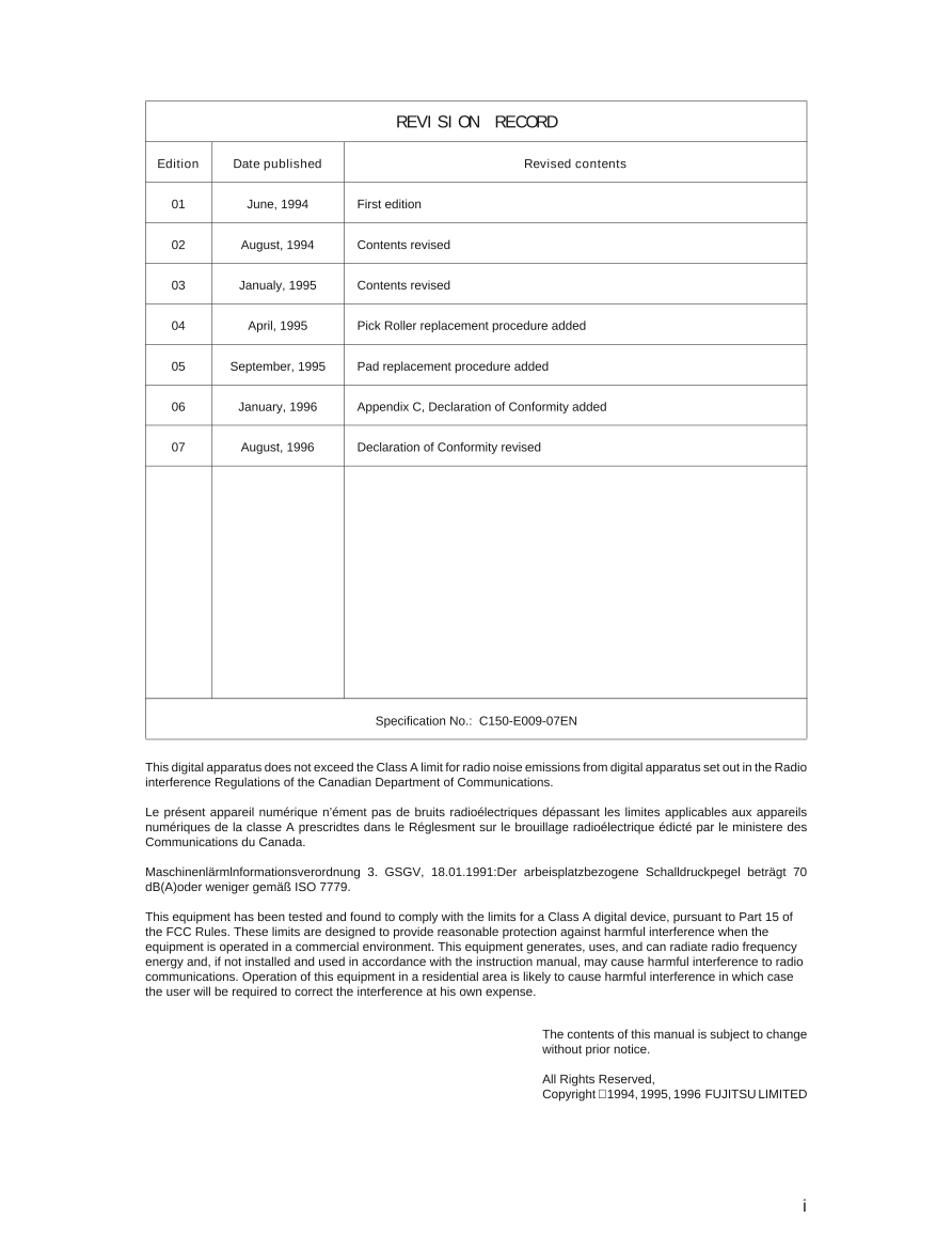
REVISION RECORD
Edition Date published Revised contents
01 June, 1994 First edition
02 August, 1994 Contents revised
03 Janualy, 1995 Contents revised
04 April, 1995 Pick Roller replacement procedure added
05 September, 1995 Pad replacement procedure added
06 January, 1996 Appendix C, Declaration of Conformity added
07 August, 1996 Declaration of Conformity revised
Specification No.: C150-E009-07EN
This digital apparatus does not exceed the Class A limit for radio noise emissions from digital apparatus set out in the Radio
interference Regulations of the Canadian Department of Communications.
Le présent appareil numérique n’ément pas de bruits radioélectriques dépassant les limites applicables aux appareils
numériques de la classe A prescridtes dans le Réglesment sur le brouillage radioélectrique édicté par le ministere des
Communications du Canada.
Maschinenlärmlnformationsverordnung 3. GSGV, 18.01.1991:Der arbeisplatzbezogene Schalldruckpegel beträgt 70
dB(A)oder weniger gemäß ISO 7779.
This equipment has been tested and found to comply with the limits for a Class A digital device, pursuant to Part 15 of
the FCC Rules. These limits are designed to provide reasonable protection against harmful interference when the
equipment is operated in a commercial environment. This equipment generates, uses, and can radiate radio frequency
energy and, if not installed and used in accordance with the instruction manual, may cause harmful interference to radio
communications. Operation of this equipment in a residential area is likely to cause harmful interference in which case
the user will be required to correct the interference at his own expense.
The contents of this manual is subject to change
without prior notice.
All Rights Reserved,
Copyright 1994, 1995, 1996 FUJITSU LIMITED
i
Conventions Special information, such as warnings, cautions are indicated as
follows:
WARNING
A WARNING indicates that personal injury may result if you do not
follow a procedure correctly.
CAUTION
A CAUTION indicates that damage to the scanner may result if you
do not follow a procedure correctly.
NOTICE
A NOTICE provides “how-to” tips or suggestions to help you perform
a procedure correctly. NOTEs are particularly useful for first-time
users.
ii
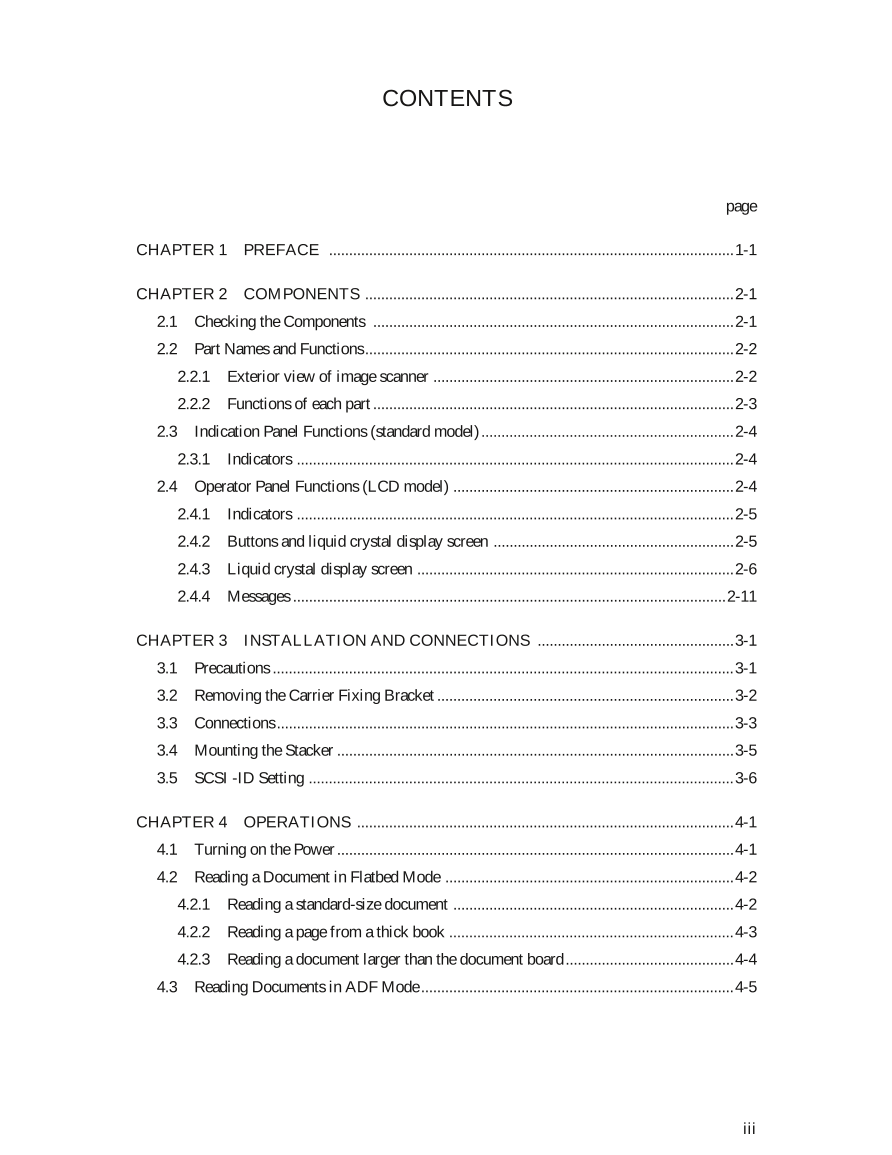
CONTENTS
page
CHAPTER 1 PREFACE .....................................................................................................1-1
CHAPTER 2 COMPONENTS ............................................................................................2-1
2.1 Checking the Components ..........................................................................................2-1
2.2 Part Names and Functions ............................................................................................2-2
2.2.1 Exterior view of image scanner ...........................................................................2-2
2.2.2 Functions of each part ..........................................................................................2-3
2.3 Indication Panel Functions (standard model) ...............................................................2-4
2.3.1 Indicators .............................................................................................................2-4
2.4 Operator Panel Functions (LCD model) ......................................................................2-4
2.4.1 Indicators .............................................................................................................2-5
2.4.2 Buttons and liquid crystal display screen ............................................................2-5
2.4.3 Liquid crystal display screen ...............................................................................2-6
2.4.4 Messages ............................................................................................................2-11
CHAPTER 3 INSTALLATION AND CONNECTIONS .................................................3-1
3.1 Precautions ...................................................................................................................3-1
3.2 Removing the Carrier Fixing Bracket ..........................................................................3-2
3.3 Connections ..................................................................................................................3-3
3.4 Mounting the Stacker ...................................................................................................3-5
3.5 SCSI -ID Setting ..........................................................................................................3-6
CHAPTER 4 OPERATIONS ..............................................................................................4-1
4.1 Turning on the Power ...................................................................................................4-1
4.2 Reading a Document in Flatbed Mode ........................................................................4-2
4.2.1 Reading a standard-size document ......................................................................4-2
4.2.2 Reading a page from a thick book .......................................................................4-3
4.2.3 Reading a document larger than the document board ..........................................4-4
4.3 Reading Documents in ADF Mode ..............................................................................4-5
iii
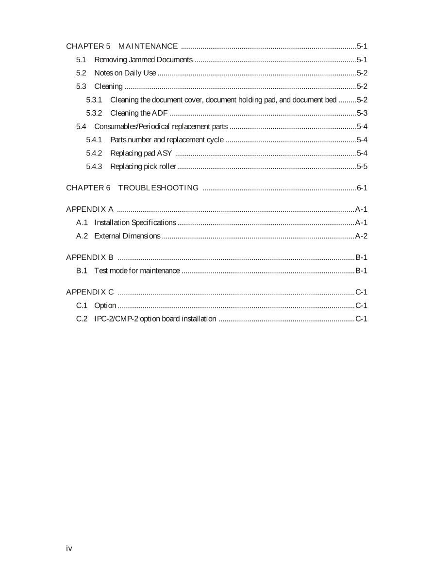
CHAPTER 5 MAINTENANCE ..........................................................................................5-1
5.1 Removing Jammed Documents ...................................................................................5-1
5.2 Notes on Daily Use ......................................................................................................5-2
5.3 Cleaning .......................................................................................................................5-2
5.3.1 Cleaning the document cover, document holding pad, and document bed .........5-2
5.3.2 Cleaning the ADF ................................................................................................5-3
5.4 Consumables/Periodical replacement parts .................................................................5-4
5.4.1 Parts number and replacement cycle ...................................................................5-4
5.4.2 Replacing pad ASY .............................................................................................5-4
5.4.3 Replacing pick roller ............................................................................................5-5
CHAPTER 6 TROUBLESHOOTING ...............................................................................6-1
APPENDIX A ..........................................................................................................................A-1
A.1 Installation Specifications ...........................................................................................A-1
A.2 External Dimensions ...................................................................................................A-2
APPENDIX B ..........................................................................................................................B-1
B.1 Test mode for maintenance .........................................................................................B-1
APPENDIX C ..........................................................................................................................C-1
C.1 Option ..........................................................................................................................C-1
C.2 IPC-2/CMP-2 option board installation ......................................................................C-1
iv
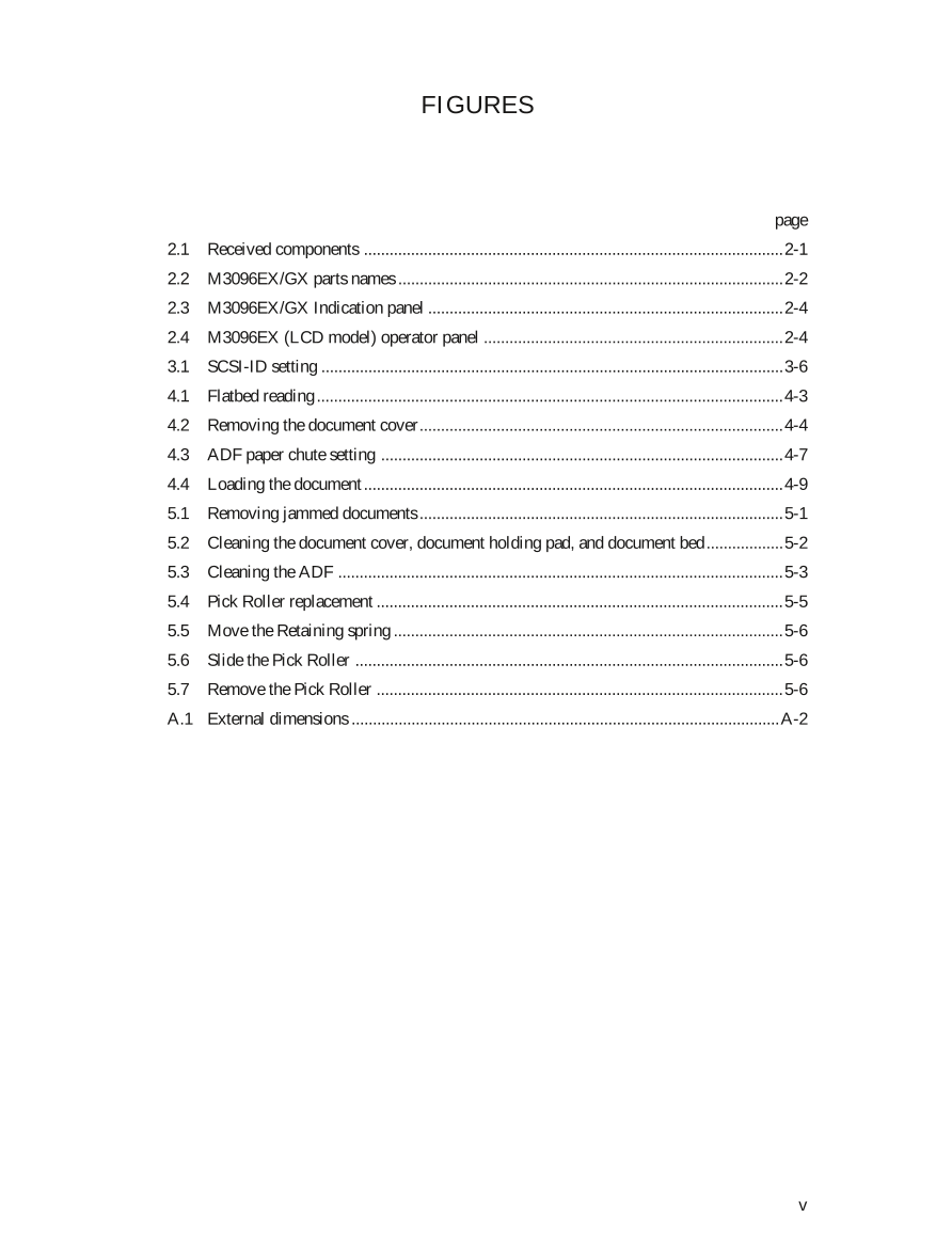
FIGURES
page
2.1 Received components ..................................................................................................2-1
2.2 M3096EX/GX parts names ..........................................................................................2-2
2.3 M3096EX/GX Indication panel ...................................................................................2-4
2.4 M3096EX (LCD model) operator panel ......................................................................2-4
3.1 SCSI-ID setting ............................................................................................................3-6
4.1 Flatbed reading .............................................................................................................4-3
4.2 Removing the document cover.....................................................................................4-4
4.3 ADF paper chute setting ..............................................................................................4-7
4.4 Loading the document ..................................................................................................4-9
5.1 Removing jammed documents .....................................................................................5-1
5.2 Cleaning the document cover, document holding pad, and document bed..................5-2
5.3 Cleaning the ADF ........................................................................................................5-3
5.4 Pick Roller replacement ...............................................................................................5-5
5.5 Move the Retaining spring ...........................................................................................5-6
5.6 Slide the Pick Roller ....................................................................................................5-6
5.7 Remove the Pick Roller ...............................................................................................5-6
A.1 External dimensions ....................................................................................................A-2
v
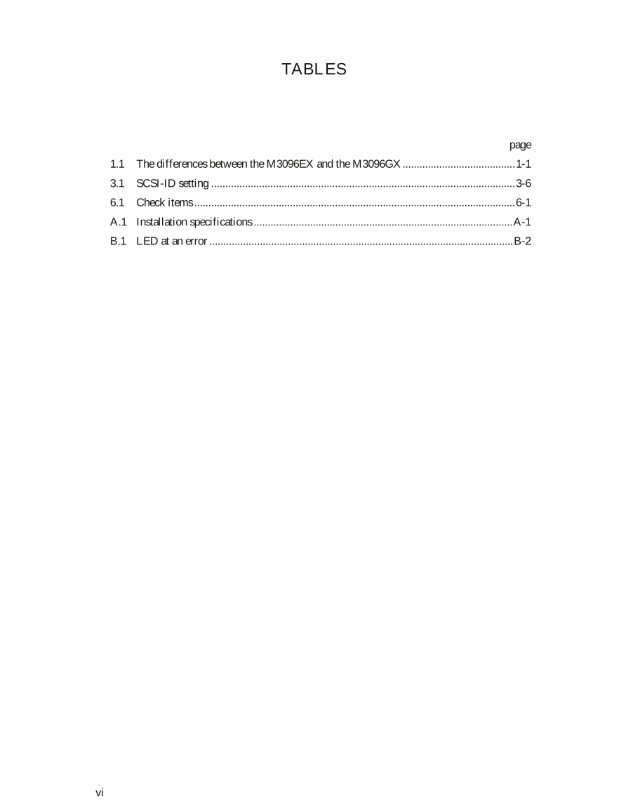
TABLES
page
1.1 The differences between the M3096EX and the M3096GX........................................1-1
3.1 SCSI-ID setting ............................................................................................................3-6
6.1 Check items ..................................................................................................................6-1
A.1 Installation specifications ............................................................................................A-1
B.1 LED at an error ............................................................................................................B-2
vi
CHAPTER 1 PREFACE
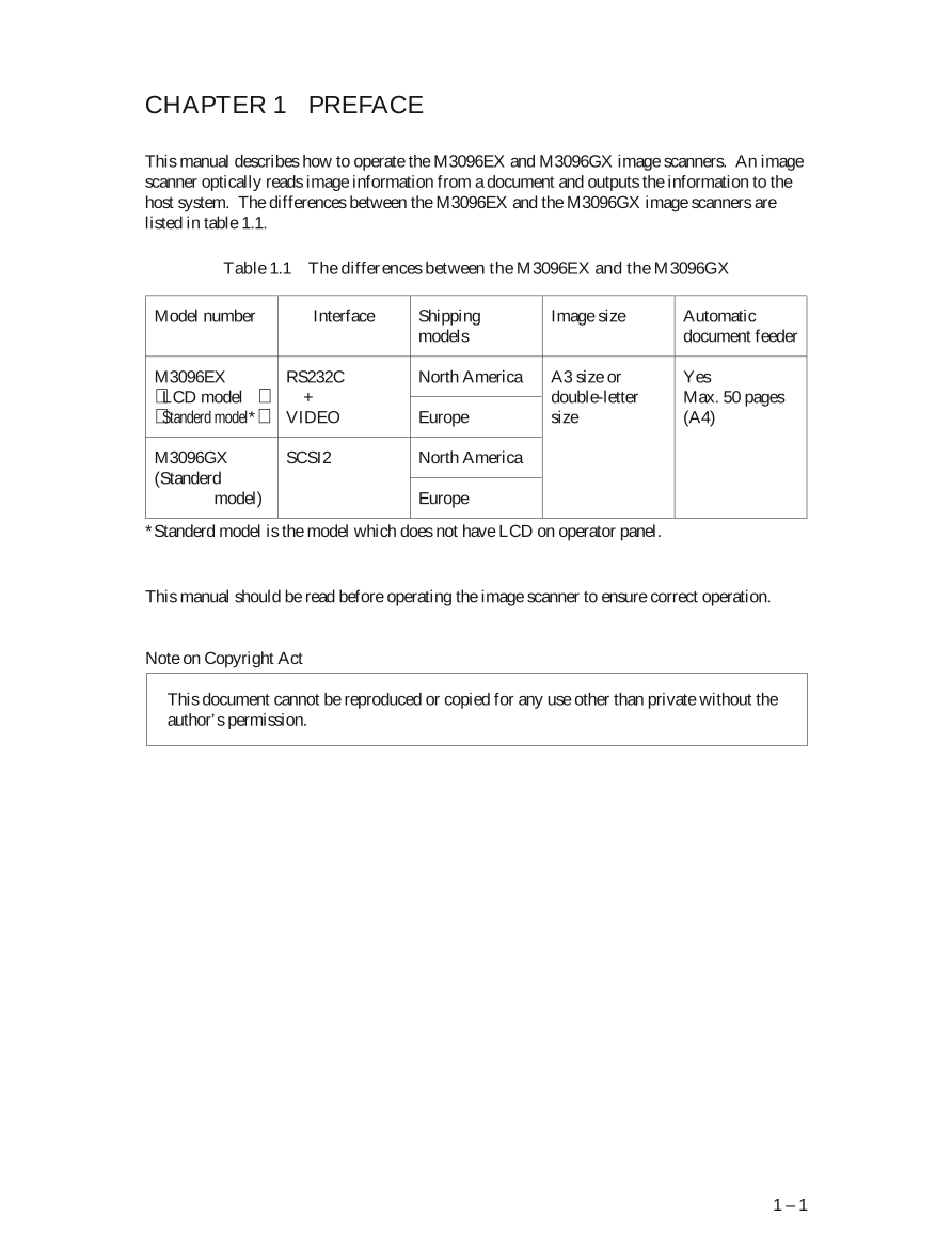
This manual describes how to operate the M3096EX and M3096GX image scanners. An image
scanner optically reads image information from a document and outputs the information to the
host system. The differences between the M3096EX and the M3096GX image scanners are
listed in table 1.1.
Table 1.1 The differences between the M3096EX and the M3096GX
Model number Interface Shipping Image size Automatic
models document feeder
M3096EX RS232C North America A3 size or Yes
LCD model + double-letter Max. 50 pages
Standerd model* VIDEO Europe size (A4)
M3096GX SCSI2 North America
(Standerd
model) Europe
*Standerd model is the model which does not have LCD on operator panel.
This manual should be read before operating the image scanner to ensure correct operation.
Note on Copyright Act
This document cannot be reproduced or copied for any use other than private without the
author’s permission.
1 – 1




 V2版本原理图(Capacitive-Fingerprint-Reader-Schematic_V2).pdf
 摄像头工作原理.doc
 VL53L0X简要说明(En.FLVL53L00216).pdf
 原理图(DVK720-Schematic).pdf
 原理图(Pico-Clock-Green-Schdoc).pdf
 原理图(RS485-CAN-HAT-B-schematic).pdf
 File:SIM7500_SIM7600_SIM7800 Series_SSL_Application Note_V2.00.pdf
 ADS1263(Ads1262).pdf
 原理图(Open429Z-D-Schematic).pdf
 用户手册(Capacitive_Fingerprint_Reader_User_Manual_CN).pdf
 CY7C68013A(英文版)(CY7C68013A).pdf
 TechnicalReference_Dem.pdf