Journal of Applied Mathematics and Physics, 2018, 6, 1886-1895
http://www.scirp.org/journal/jamp
ISSN Online: 2327-4379
ISSN Print: 2327-4352
Analysis of Electrical Dipoles Interaction Forces
as a Function of the Distance and of the Form of
Electrical Force Law
Ioan Has1, Simona Miclaus1, Aurelian Has2
1Land Forces Academy, Sibiu, Rm. Valcea, Romania
2Independent Researcher, Rm. Valcea, Romania
How to cite this paper: Has, I., Miclaus, S.
and Has, A. (2018) Analysis of Electrical
Dipoles Interaction Forces as a Function of
the Distance and of the Form of Electrical
Force Law. Journal of Applied Mathematics
and Physics, 6, 1886-1895.
https://doi.org/10.4236/jamp.2018.69160
Received: August 20, 2018
Accepted: September 17, 2018
Published: September 20, 2018
Copyright © 2018 by authors and
Scientific Research Publishing Inc.
This work is licensed under the Creative
Commons Attribution International
License (CC BY 4.0).
http://creativecommons.org/licenses/by/4.0/
Open Access
Abstract
Here, we initially introduced and demonstrated two principles: orientation
OR principle and attraction AT principle of electrical dipoles. The OR prin-
ciple stipulates that any two electrical dipoles P1A, P1B, from two bodies A
and B, at any distance in the free state each, will be reciprocally oriented pa-
rallel and in the same sense if the electrical interaction forces F between them
are of decreasing type with distance r. If the electrical interaction forces F are
of increasing type with distance, the two dipoles will be reciprocally oriented
parallel but on the opposite sense. The AT principle stipulate that any two
electrical dipoles P1A, P1B, at any distance in the free state each, will present
always a reciprocal force of attraction FD in both cases of orientation accor-
dingly to OR principle in case of any type of electrical force F decreasing or
increasing with distance. These findings may complete our previous work
where we found that FD force, between two electrical dipoles P1A, P1B consi-
dered at atomic and nuclear level, is in fact the actual gravitation Newton
force FN. The paper must be considered together with this work for more
consistency.
Keywords
Electrical Forces, Completed Coulomb’s Law, Electric Dipoles Interactions,
Torsion Moment of Orientation, Attraction Force between Two Dipoles Is
Gravitation
1. Observations about Actual Explanation for the Absence of
Electrical Interactions at Long Distances
Today, it is largely admitted that at long distances, at astronomical scales, at
DOI: 10.4236/jamp.2018.69160 Sep. 20, 2018
1886
Journal of Applied Mathematics and Physics
�
I. Has et al.
planetary scale and even at building scales, the electrical forces FC given by clas-
sical Coulomb’s law of electrical forces:
kq q
1 2
2
r
; with k = 1/4πε0; (1), (1’)
q q
1 2
r
4π
ε
0
=
F
C
=
2
between two neutral bodies are negligible and should not be taken into account,
as it happens today.
The only forces considered today at such long distances are the gravitational
forces FN given by classical Newton’s law.
F
N
= −
G
Mm
2
r
(2)
This affirmation excludes the electromagnetic phenomena which consist of
more complex combinations of electric and magnetic forces originated at atomic
scales.
But it is unlikely that the interaction forces acting between two electrical
charges q1, q2 may be perfectly described by mathematical simple laws as in (1),
at any distances r, and of any scales, in the micro and macro universe.
At this point of our analysis, the above affirmation is justified by the reality
complexity or its infinity and also by discrepancies between calculus results of
actual simple laws from (1), (2) and some experimental measurements and ob-
servations concerning these forces, reported in the past.
Discrepancies concerning the Coulomb’s law are confirmed by modern expe-
riments, which allow scientists to conclude that in the case of very short dis-
tances (such as between molecules, atoms, nuclei, particles) the law (1) is not
precisely correct [1], but also it has not yet been proven in the case of long dis-
tances [2]. In such circumstances, we can conclude that the Coulomb’s law in the
current form (1) is not perfect and that it can be improved.
For a more accurate description of the infinite reality, including ether pres-
ence which will be considered throughout this paper, as we previously demon-
strated [3] [4] [5] [6], the most appropriate (but not singular mathematical)
mode of electrical forces description, will be probable, a long or infinite series of
successive powers of the 1/r distance.
In the present, it is accepted that macroscopic bodies have a random distribu-
tion of +q and –q charges, which will generate a random distribution of dipoles
in any direction, and all coefficients ki from (3) are canceled [7].
φ
M
=
k
k
1
r
ε ε
0
0
0
r
+
+
2
k
2
r
ε
0
3
+ (3)
This means that starting from small distances from any neutral body to infi-
nite distances, the influence of the electric charges from that body is considered
today to be null. But we will show below that this approach isn’t correctly justi-
fied.
1887
Journal of Applied Mathematics and Physics
DOI: 10.4236/jamp.2018.69160
�
I. Has et al.
DOI: 10.4236/jamp.2018.69160
2. Our New Hypothesis and Principles, Concerning the
Dipole Interactions at Long Distances
2.1. Justification of Introducing the Two New Principles of Electric
Dipoles Interaction, OR and AT
Despite the fact that bodies A, B…, are neutral, the +q and –q charges are in fact
always separated in space at atomic and nuclear scale, and consequently every
charge +q or –q will exert its electrical interaction force FC to infinite distance
according to (1) or to a corrected Coulomb law as in [8] [9] [10] [11].
So in nature practically all the matter must be regarded as being organized al-
ways as electrical dipoles P1, P2, P3… as result of Coulomb law action even at
smallest scales.
We will show next, that neglecting electrical forces and their potential even for
distant bodies is not correct because we can admit and demonstrate the follow-
ing two principles:
a) OR principle of the reciprocal orientation of distant dipoles.
b) AT principle of the permanent attraction of oriented distant dipoles.
2.2. Presentation and Justification of OR Principle
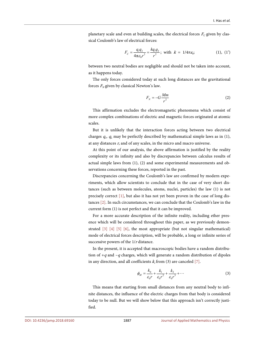
In order to demonstrate the OR principle, we can calculate the torsion moments
+M (clockwise) and −M (counterclockwise) created by an oriented dipole P2
from body B upon an un-oriented dipole P1 (disposed at 90˚ in body A).
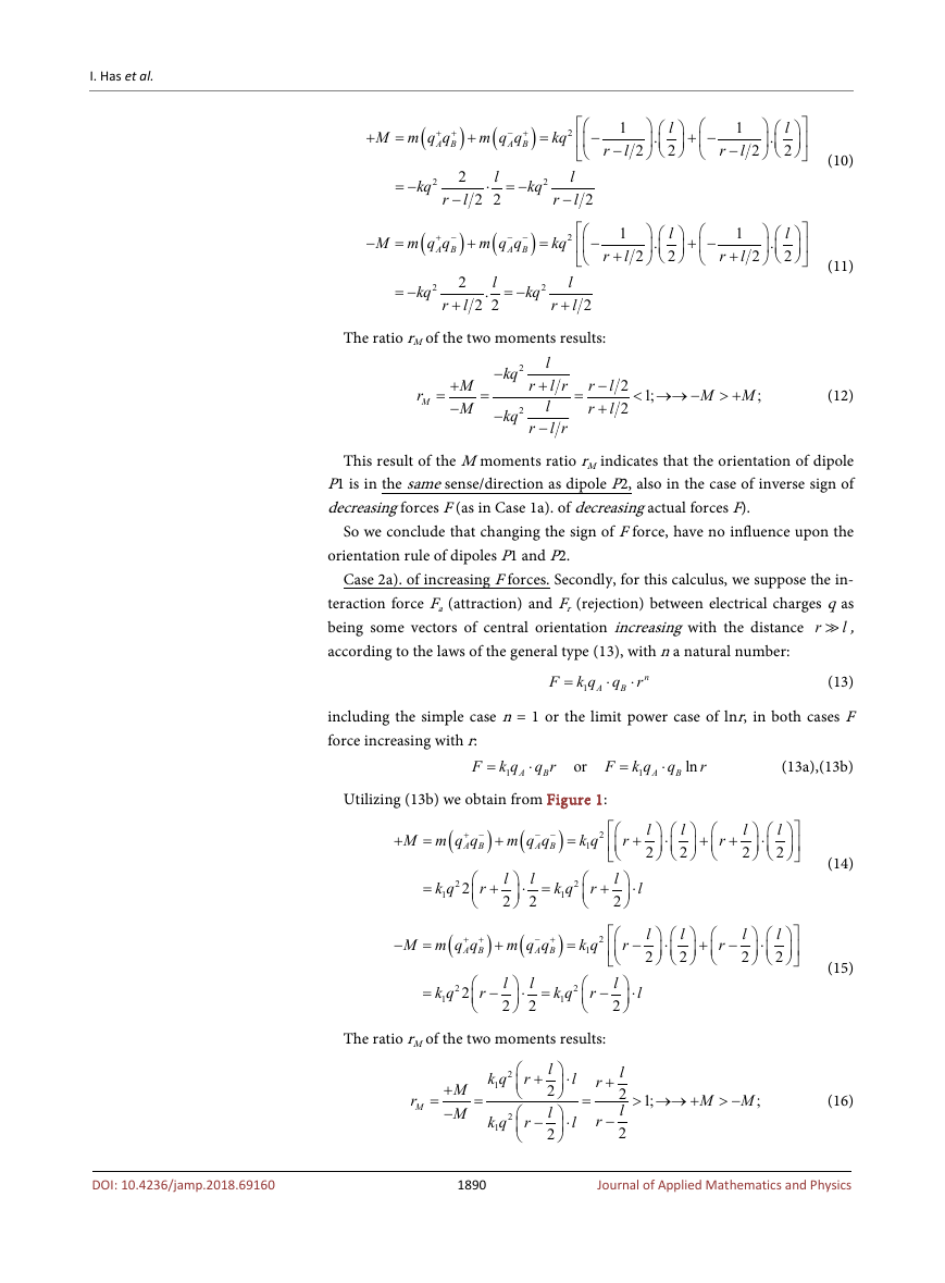
In this situation (Figure 1) we can distinguish two cases, depending on the
variation mode with distance r, of interaction Coulomb’s forces F (reference
frame xOy is attached to A body).
Case 1a). of decreasing F forces. Firstly, for this calculus, we suppose the inte-
raction forces Fa (attraction for +q/−q charges when Fa < 0, according to (1)) and
Fr (rejection for +q/+q or –q/−q charges, Fr > 0, according to (1)) between elec-
trical charges +q and –q as being some vectors F of central orientation de-
creasing with the increasing distance r
l , between body A and body B ac-
cording to the law of the general type (4), generalizing (1), with n a natural
number:
F
=
q q
1 2
r
4π
ε
0
n
=
kq q
A B
n
r
(4)
including the simple case n = 1:
F
=
kq q
A B
r
(4a)
Product qA.qB from (4), (4a) comprises for simplicity, also coefficients k/4πε0.
Utilizing (4a), we obtained from Figure 1 the clockwise torsion moment +M and
counterclockwise −M moment, given upon P1 dipole, by forces F from P2 di-
pole, as follows:
M F
=
l
2
=
(
m q q
A B
)
(5)
1888
Journal of Applied Mathematics and Physics
�
I. Has et al.
Figure 1. Situation of two distant dipoles P1 and P2 from bodies A and B, which manifest
a reciprocal orientation with xOy frame attached to A body.
where function m represents the components of total M moments, given by var-
ious pairs of q charges.
+ −
M m q q
A B
=
(
+
)
+
(
− −
m q q
A B
)
=
2
kq
1
l
+
r
.
l
2
2
+
1
l
+
r
.
l
2
2
=
2
kq
2
l
+
r
l
.
2 2
=
2
kq
l
l
+
r
2
+ +
M m q q
A B
=
(
−
)
+
(
− +
m q q
A B
)
=
2
kq
1
l
−
r
.
l
2
2
+
1
l
−
r
.
l
2
2
=
2
kq
2
l
−
r
l
.
2 2
=
2
kq
l
l
−
r
2
(6)
(7)
The ratio rM of the two moments results from (6) and (7):
r
M
=
+
−
M
M
=
2
kq
2
kq
l
l r
+
l
l r
−
r
r
=
r
r
−
+
l
l
2 1;
< →→ −
2
M
> +
M
;
(8)
This result of M moments ratio rM indicates that the orientation of dipole P1
will be in the same sense/direction as dipole P2, in this case of the decreasing
positive forces F.
Case 1b). of decreasing F forces and sign change. We now must calculate what
happens in the hypothetical case when the forces F from (4) and (4a) will change
the sign from positive +F to negative −F forces, including the simple case n = 1:
F
= −
kq q
A B
r
(9)
In this modified Case 1b), we admit hypothetically, an inversion of the actual
physical rule (attraction force –Fa between +q and –q charges), becoming repul-
sion force +Fr between +q and –q charges and attraction force –Fa between +q
and +q or between –q and –q charges.
In this modified Case 1b) the Equations (6) and (7) becomes, considering the
same senses of rotation of +M and –M moments, as in Figure 1:
1889
Journal of Applied Mathematics and Physics
DOI: 10.4236/jamp.2018.69160
�
I. Has et al.
+
−
)
=
2
kq
−
1
l
−
r
.
l
2
2
+ −
1
l
−
r
.
l
2
2
+ +
M m q q
A B
=
+
(
(
= −
kq
2
r
= −
kq
2
r
)
2
l
−
)
2
l
+
(
− +
m q q
A B
l
⋅ = −
2 2
(
− −
m q q
A B
l
.
2 2
= −
kq
2
l
l
−
r
2
kq
2
l
l
+
r
2
+ −
M m q q
A B
=
+
)
=
2
kq
−
1
l
+
r
.
l
2
2
+ −
1
l
+
r
.
l
2
2
(10)
(11)
The ratio rM of the two moments results:
r
M
=
+
−
M
M
=
2
−
kq
2
−
kq
l
l r
+
l
l r
−
r
r
=
r
r
−
+
l
l
2 1;
< →→ −
2
M
> +
M
;
(12)
This result of the M moments ratio rM indicates that the orientation of dipole
P1 is in the same sense/direction as dipole P2, also in the case of inverse sign of
decreasing forces F (as in Case 1a). of decreasing actual forces F).
So we conclude that changing the sign of F force, have no influence upon the
orientation rule of dipoles P1 and P2.
Case 2a). of increasing F forces. Secondly, for this calculus, we suppose the in-
teraction force Fa (attraction) and Fr (rejection) between electrical charges q as
being some vectors of central orientation increasing with the distance r
l ,
according to the laws of the general type (13), with n a natural number:
F k q
1
=
A
⋅
q
B
n
⋅
r
(13)
including the simple case n = 1 or the limit power case of lnr, in both cases F
force increasing with r:
F k q
1
=
A
⋅
q r
B
or
F k q
1
=
A
⋅
q
B
ln
r
(13a),(13b)
Utilizing (13b) we obtain from Figure 1:
+ −
M m q q
A B
(
− −
m q q
A B
k q
1
+
=
=
)
+
(
)
2
=
2
k q
1
2
r
+
l
2
l
⋅ =
2
2
k q
1
r
+
+ +
M m q q
A B
=
(
)
+
(
− +
m q q
A B
)
=
2
k q
1
−
=
2
k q
1
2
r
−
l
2
l
⋅ =
2
2
k q
1
r
−
l
2
l
2
l
2
⋅
l
2
+
r
+
l
2
⋅
l
2
(14)
l
2
⋅
l
2
+
r
−
l
2
⋅
l
2
(15)
r
+
⋅
l
r
−
⋅
l
The ratio rM of the two moments results:
r
M
=
+
−
M
M
=
2
k q
1
2
k q
1
r
r
l
+
2
l
2
−
⋅
l
⋅
l
=
r
+
r
−
l
2
l
2
> →→ +
1;
M
> −
M
;
(16)
1890
Journal of Applied Mathematics and Physics
DOI: 10.4236/jamp.2018.69160
�
I. Has et al.
This result of M moments ratio rM indicates that the orientation of dipole P1 is
in the opposite sense/direction as dipole P2, in case of increasing positive forces.
In Case 2b), of increasing F forces and sign change, when the force F is also as
increasing with r type, but of reversed sign, is similar to the Case 1b). And hence
the result of the calculus of rM ratio will be similar: indicating that the orienta-
tion of dipole P1 is in the opposite sense/direction as dipole P2. (as in Case 1b).
in this case of increasing positive forces F.
And so at points Case 1) and Case 2), the OR principle was demonstrated.
The OR principle stipulate that in case of decreasing electrical forces F with r
the orientation of dipole P1 is in the same sense/direction as dipole P2 irrespec-
tive of sign of F.
But in case of increasing electrical forces F with r, the orientation of dipole P1
is in the opposite sense/direction as dipole P2 irrespective of sign of F.
2.3. Presentation and Justification of AT Principle
In order to demonstrate the AT principle, will be calculated forwards the resul-
tant force R, appearing between two oriented dipoles, P1A and P1B, according to
OR principle, given by forces of attraction Fa and by forces of repulsion Fr exist-
ing between +q and –q charges, as in actual FC or completed F, Coulomb’s law.
It must determine if the force R is the attraction or repulsion force, as a
function of the form of the electric force law F.
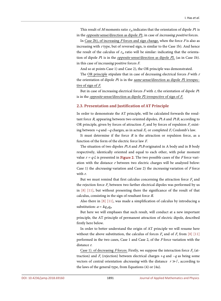
The situation of two dipoles P1A and P1B originated in A body and in B body
respectively, identically oriented and equal to each other, with polar moment
value r = q∙l, is presented in Figure 2. The two possible cases of the F force vari-
ation with the distance r between two electric charges will be analyzed below:
Case 1) the decreasing variation and Case 2) the increasing variation of F force
with r.
But we must remind that first calculus concerning the attraction force Fa and
the rejection force Fr between two farther electrical dipoles was performed by us
in [8] [11], but without presenting there the significance of the result of that
calculus, consisting in the sign of resultant force R.
Also there in [8] [11], was made a simplification of calculus by introducing a
substitution: α = kqAqB.
But here we will emphases that such result, will conduct at a new important
principle, the AT principle of permanent attraction of electric dipole, described
firstly here below.
In order to better understand the origin of AT principle we will resume here
without the above substitution, the calculus of forces Fa and of Fr from [8] [11]
performed in the two cases, Case 1 and Case 2, of the F force variation with the
distance r.
Case 1). of decreasing F forces. Firstly, we suppose the interaction force Fa (at-
traction) and Fr (rejection) between electrical charges +q and –q as being some
vectors of central orientation decreasing with the distance r
l , according to
the laws of the general type, from Equations (4) or (4a).
1891
Journal of Applied Mathematics and Physics
DOI: 10.4236/jamp.2018.69160
�
I. Has et al.
Figure 2. Forces F acting between a pair of identical oriented dipoles P1A and P1B con-
sidered at atomic and nuclear level, from A and B bodies with xOy frame attached to A
body.
From Figure 2, we now can calculate directly by simple algebra, utilizing Eq-
uation (4b), the total force upon each dipole, exerted by the other dipole. Here in
calculus, we consider the + sign for force values having the sense of real force as
in Figure 2, which corresponds to the attraction force Fa (Fa < 0) and to repul-
sion force Fr (Fr > 0), forces exerted by the charges +q, −q, as in Coulomb law
(4).
From Figure 2 notating – A
q
, we consider
first, the forces exerted upon P1A dipole by a P1B dipole. Utilizing the simple
case (4b) the resultant forces Fa and Fr values results as follows:
q−→ and having
− +
q q
A B
+ −
q q
A B
=
A
F
A
=
A
F
a
1
+
A
F
a
2
=
− +
kq q
A B
r
+
+ −
kq q
A B
l
r
2
+
=
− +
kq q
A B
r
2
(
r r
+
+
l
2
l
2
)
(17)
F
R
=
F
r
A
1
+
F
r
A
2
=
− −
kq q
A B
r
l
+
+
+ +
kq q
A B
r
l
+
=
2
− −
kq q
A B
1
+
)
l
(
r
(18)
If we rewrite the expression from the denominator from (17), one obtains:
(
r r
From (19) and admitting r
)
l
(
r
+
=
+
l
2
)2
l it results:
(
r r
+
l
2
+
(
r
<
)
2
− (19)
l
)2
l
(20)
Introducing (20) in (17) and comparing with (18) it results:
F
a
=
+ −
kq q
A B
r
2
(
r r
+
+
l
2
l
2
− −
kq q
A B
r
2
(
r
l
2
+
)2
l
+
=
F
r
(21)
>
)
F>
r
(22)
From (22) it results that in the case of forces F of the type as in Equations (4),
(4b) decreasing (n = +1) with the r distance, the attraction force Fa will be great-
F
a
DOI: 10.4236/jamp.2018.69160
1892
Journal of Applied Mathematics and Physics
�
I. Has et al.
er than the repulsion force Fr and finally an attraction force Ra = Fa − Fr > 0 be-
tween the two identically oriented dipoles P1A, P1B results. This result is correct
even if the power of r is any n > 1, as can easily be demonstrated.
Case 2) of increasing F forces. Let’s suppose the force F increases with the dis-
tance r, including a law of the form (13b).
q
=
⋅
F k q
1
(23)
with coefficient k1 being similar with coefficient k from Equation (4a) but having
the appropriate measure units considering that the term lnr must be adimen-
sional.
ln
r
A
B
Again from Figure 2, for identically oriented dipoles P1A, P1B (Figure 2), the
total forces upon P1A dipole utilizing (23) will be:
l
2
ln
ln
+ −
k q q
A B
1
− +
k q q
A B
1
A
F
a
2
A
F
a
1
F
a
=
(
r
r
+
+
=
+
)
=
− +
k q q
A B
1
ln
(
r r
+
l
2
F
r
=
F
r
A
1
+
F
r
A
2
=
− −
k q q
A B
1
ln
(
r
)
+ +
l
+ +
k q q
A B
1
ln
(
r
+
)
l
=
− −
k q q
A B
1
ln
(
r
+
l
)
(24)
)2
(25)
Comparing F and Fr from Equations (24) and (25), and considering Equation
(20) it results:
F
a
=
− +
k q q
A B
1
ln
(
r r
+
l
2
)
<
− −
k q q
A B
1
ln
(
r
+
)2
l
=
F
r
(26)
F
a
F<
r
(27)
From (27) it results that in the case of increasing F forces of the type from
(23), the repulsion force Fr between two identically oriented dipoles P1A, P1B,
will be greater than the attractive force Fa and the resultant force Rr = Fr − Fa > 0,
will be a repulsion force. This result is correct even if the increasing variation has
the general form F = α'rn with n > 1, as it can easily be demonstrated.
But in this Case 2 of increasing F forces (23), the natural orientation of two
dipoles becomes reverted compared with those from Figure 2, according to the
OR principle from Section 2.2., and the interaction force between the two di-
poles P1A and P1B will be again an attraction force Ra = Fr − Fa < 0 as for de-
creasing forces.
So, the AT principle stipulate that in case of decreasing electrical forces F with
r an attraction force Ra between the two identically naturally oriented dipoles
P1A, P1B results.
Also in case of increasing electrical forces F with r, because the two dipoles
P1A, P1B will be naturally inverse oriented accordingly to OR principle, AT
principle stipulate that again an attraction force Ra between the two dipoles P1A,
P1B results.
And so, the simultaneous action of OR principle and of AT principle, will give
birth of a permanent attraction between two any electrical dipoles irrespective of
F force type.
The above analytical calculus and its results, yields the above OR principle and
AT principle, whose result must be real.
This effect of permanent attraction of electrical dipoles P1A, P1B can be ob-
served also in case of a group in any number of usual magnets mi as spheres of
1893
Journal of Applied Mathematics and Physics
DOI: 10.4236/jamp.2018.69160
�


 2023年江西萍乡中考道德与法治真题及答案.doc
 2012年重庆南川中考生物真题及答案.doc
 2013年江西师范大学地理学综合及文艺理论基础考研真题.doc
 2020年四川甘孜小升初语文真题及答案I卷.doc
 2020年注册岩土工程师专业基础考试真题及答案.doc
 2023-2024学年福建省厦门市九年级上学期数学月考试题及答案.doc
 2021-2022学年辽宁省沈阳市大东区九年级上学期语文期末试题及答案.doc
 2022-2023学年北京东城区初三第一学期物理期末试卷及答案.doc
 2018上半年江西教师资格初中地理学科知识与教学能力真题及答案.doc
 2012年河北国家公务员申论考试真题及答案-省级.doc
 2020-2021学年江苏省扬州市江都区邵樊片九年级上学期数学第一次质量检测试题及答案.doc
 2022下半年黑龙江教师资格证中学综合素质真题及答案.doc