AFRL-RB-WP-TR-2011-3071
This Report Supersedes AFRL-RB-WP-TR-2009-3015
MISSILE DATCOM
User’s Manual – 2011 Revision
Christopher Rosema, Joshua Doyle, Lamar Auman, Mark Underwood
Army Aviation &Missile Research, Development and Engineering Center
William Blake
Air Force Research Laboratory
MARCH 2011
Final Report
Approved for public release; distribution unlimited.
See additional restrictions described on inside pages
AIR FORCE RESEARCH LABORATORY
AIR VEHICLES DIRECTORATE
WRIGHT-PATTERSON AIR FORCE BASE, OH 45433-7542
AIR FORCE MATERIEL COMMAND
UNITED STATES AIR FORCE
�
NOTICE
Using Government drawings, specifications, or other data included in this document for any
purpose other than Government procurement does not in any way obligate the U.S. Government.
The fact that the Government formulated or supplied the drawings, specifications, or other data does
not license the holder or any other person or corporation; or convey any rights or permission to
manufacture, use, or sell any patented invention that may relate to them.
This report was cleared for public release by the Air Force Research Laboratory –Wright Patterson
Public Affairs Office and is available to the general public, including foreign nationals. Copies may
be obtained from the Defense Technical Information Center (DTIC) (http://www.dtic.mil).
AFRL-RB-WP-TR-2011-3071 HAS BEEN REVIEWED AND IS APPROVED FOR
PUBLICATION IN ACCORDANCE WITH ASSIGNED DISTRIBUTION STATEMENT.
This report is published in the interest of scientific and technical information exchange, and its publication
does not constitute the Government’s approval or disapproval of its ideas or findings.
* Disseminated copies will show “//signature//” stamped or typed above the signiature blocks.
�
REPORT DOCUMENTATION PAGE
Form Approved
OMB No. 0704-0188
The public reporting burden for this collection of information is estimated to average 1 hour per response, including the time for reviewing instructions, searching existing data sources, searching existing data
sources, gathering and maintaining the data needed, and completing and reviewing the collection of information. Send comments regarding this burden estimate or any other aspect of this collection of
information, including suggestions for reducing this burden, to Department of Defense, Washington Headquarters Services, Directorate for Information Operations and Reports (0704-0188), 1215 Jefferson
Davis Highway, Suite 1204, Arlington, VA 22202-4302. Respondents should be aware that notwithstanding any other provision of law, no person shall be subject to any penalty for failing to comply with a
collection of information if it does not display a currently valid OMB control number. PLEASE DO NOT RETURN YOUR FORM TO THE ABOVE ADDRESS.
1. REPORT DATE (DD-MM-YY)
2. REPORT TYPE
03-31-11
4. TITLE AND SUBTITLE
Final
MISSILE DATCOM
User’s Manual – 2011 Revision
6. AUTHOR(S)
Lamar Auman, Joshua Doyle, Christopher Rosema, Mark Underwood,
William Blake
3. DATES COVERED (From - To)
01 October 2008 – 31 March 2011
5a. CONTRACT NUMBER
N/A
5b. GRANT NUMBER
5c. PROGRAM ELEMENT NUMBER
62201F
5d. PROJECT NUMBER
A07T
5e. TASK NUMBER
5f. WORK UNIT NUMBER
0H
7. PERFORMING ORGANIZATION NAME(S) AND ADDRESS(ES)
Aviation & Missile Research, Development and
Engineering Center
Systems Simulation & Development Directorate
Redstone Arsenal AL 35898
United States Army
Air Force Research Laboratory
Air Vehicles Directorate
Wright-Patterson Air Force Base, OH 45433
United States Air Force
9. SPONSORING/MONITORING AGENCY NAME(S) AND ADDRESS(ES)
Aviation & Missile Research, Development and
Engineering Center
Systems Simulation & Development Directorate
Redstone Arsenal AL 35898
United States Army
Air Force Research Laboratory
Air Vehicles Directorate
Wright-Patterson Air Force Base, OH 45433
United States Air Force
8. PERFORMING ORGANIZATION
REPORT NUMBER
AFRL-RB-WP-TR-2011-3071
10. SPONSORING/MONITORING AGENCY
ACRONYM(S)
AFRL/RBCA
11. SPONSORING/MONITORING AGENCY
REPORT NUMBER(S)
AFRL-RB-WP-TR-2011-3071
12. DISTRIBUTION/AVAILABILITY STATEMENT
Approved for public release; distribution unlimited.
13. SUPPLEMENTARY NOTES
PAO Case Number: 88ABW-2011-2794; Clearance Date: 24 May 2011. Report contains color.
14. ABSTRACT
This report is a User’s Manual for the 2011 Revision of the Missile Datcom computer program. It supersedes
AFRL-VA-WP-TR-2009-3015.
15. SUBJECT TERMS
aerodynamics, stability and control, missile
16. SECURITY CLASSIFICATION OF:
17. LIMITATION
18. NUMBER
a. REPORT
Unclassified
b. ABSTRACT
Unclassified
c. THIS PAGE
Unclassified
OF ABSTRACT:
OF PAGES
SAR
109
19a. NAME OF RESPONSIBLE PERSON (Monitor)
William B. Blake
19b. TELEPHONE NUMBER (Include Area Code)
937-255-6764
Standard Form 298 (Rev. 8-98)
Prescribed by ANSI Std. Z39-18
i
�
ii
�
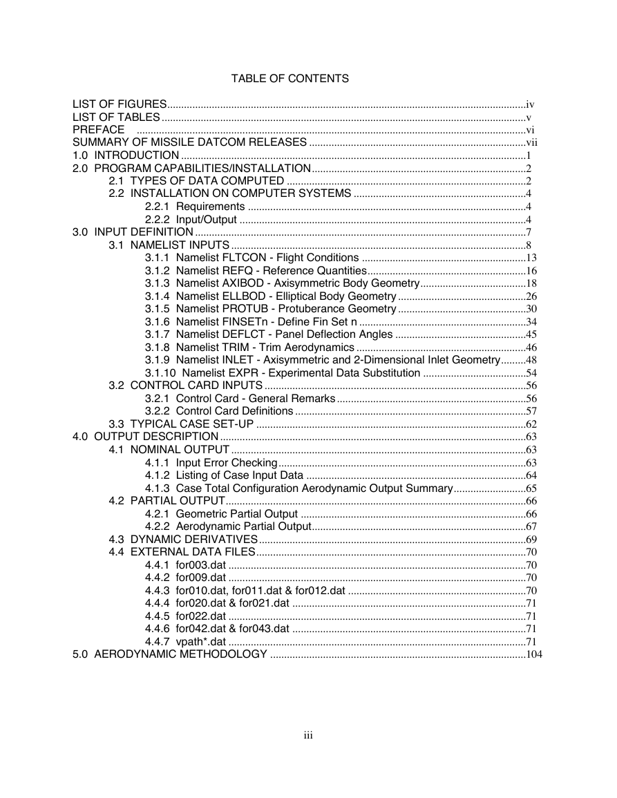
TABLE OF CONTENTS
LIST OF FIGURES ................................................................................................................................. iv
LIST OF TABLES ................................................................................................................................... v
............................................................................................................................................ vi
PREFACE
SUMMARY OF MISSILE DATCOM RELEASES .............................................................................. vii
1.0 INTRODUCTION ............................................................................................................................ 1
2.0 PROGRAM CAPABILITIES/INSTALLATION ............................................................................. 2
2.1 TYPES OF DATA COMPUTED ...................................................................................... 2
2.2 INSTALLATION ON COMPUTER SYSTEMS .............................................................. 4
2.2.1 Requirements .................................................................................................... 4
2.2.2 Input/Output ....................................................................................................... 4
3.0 INPUT DEFINITION ....................................................................................................................... 7
3.1 NAMELIST INPUTS .......................................................................................................... 8
3.1.1 Namelist FLTCON - Flight Conditions ........................................................... 13
3.1.2 Namelist REFQ - Reference Quantities ......................................................... 16
3.1.3 Namelist AXIBOD - Axisymmetric Body Geometry ...................................... 18
3.1.4 Namelist ELLBOD - Elliptical Body Geometry .............................................. 26
3.1.5 Namelist PROTUB - Protuberance Geometry .............................................. 30
3.1.6 Namelist FINSETn - Define Fin Set n ............................................................ 34
3.1.7 Namelist DEFLCT - Panel Deflection Angles ............................................... 45
3.1.8 Namelist TRIM - Trim Aerodynamics ............................................................. 46
3.1.9 Namelist INLET - Axisymmetric and 2-Dimensional Inlet Geometry ......... 48
3.1.10 Namelist EXPR - Experimental Data Substitution ..................................... 54
3.2 CONTROL CARD INPUTS .............................................................................................. 56
3.2.1 Control Card - General Remarks .................................................................... 56
3.2.2 Control Card Definitions ................................................................................... 57
3.3 TYPICAL CASE SET-UP ................................................................................................. 62
4.0 OUTPUT DESCRIPTION .............................................................................................................. 63
4.1 NOMINAL OUTPUT .......................................................................................................... 63
4.1.1 Input Error Checking ......................................................................................... 63
4.1.2 Listing of Case Input Data ............................................................................... 64
4.1.3 Case Total Configuration Aerodynamic Output Summary .......................... 65
4.2 PARTIAL OUTPUT............................................................................................................ 66
4.2.1 Geometric Partial Output ................................................................................. 66
4.2.2 Aerodynamic Partial Output............................................................................. 67
4.3 DYNAMIC DERIVATIVES ................................................................................................ 69
4.4 EXTERNAL DATA FILES ................................................................................................. 70
4.4.1 for003.dat ........................................................................................................... 70
4.4.2 for009.dat ........................................................................................................... 70
4.4.3 for010.dat, for011.dat & for012.dat ................................................................ 70
4.4.4 for020.dat & for021.dat .................................................................................... 71
4.4.5 for022.dat ........................................................................................................... 71
4.4.6 for042.dat & for043.dat .................................................................................... 71
4.4.7 vpath*.dat ........................................................................................................... 71
5.0 AERODYNAMIC METHODOLOGY ............................................................................................ 104
iii
�
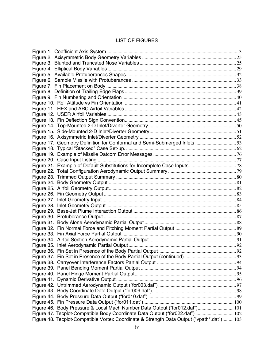
LIST OF FIGURES
Figure 1. Coefficient Axis System ........................................................................................................... 3
Figure 2. Axisymmetric Body Geometry Variables ............................................................................ 25
Figure 3. Blunted and Truncated Nose Variables .............................................................................. 25
Figure 4. Elliptical Body Variables ........................................................................................................ 29
Figure 5. Available Protuberances Shapes ......................................................................................... 32
Figure 6. Sample Missile with Protuberances .................................................................................... 33
Figure 7. Fin Placement on Body ......................................................................................................... 38
Figure 8. Definition of Trailing Edge Flaps .......................................................................................... 39
Figure 9. Fin Numbering and Orientation ............................................................................................ 40
Figure 10. Roll Attitude vs Fin Orientation .......................................................................................... 41
Figure 11. HEX and ARC Airfoil Variables .......................................................................................... 42
Figure 12. USER Airfoil Variables ........................................................................................................ 43
Figure 13. Fin Deflection Sign Convention .......................................................................................... 45
Figure 14. Top-Mounted 2-D Inlet/Diverter Geometry ....................................................................... 50
Figure 15. Side-Mounted 2-D Inlet/Diverter Geometry ...................................................................... 51
Figure 16. Axisymmetric Inlet/Diverter Geometry .............................................................................. 52
Figure 17. Geometry Definition for Conformal and Semi-Submerged Inlets ................................. 53
Figure 18. Typical “Stacked” Case Set-up. ......................................................................................... 62
Figure 19. Example of Missile Datcom Error Messages ................................................................... 76
Figure 20. Case Input Listing ................................................................................................................ 77
Figure 21. Example of Default Substitutions for Incomplete Case Inputs ...................................... 78
Figure 22. Total Configuration Aerodynamic Output Summary ....................................................... 79
Figure 23. Trimmed Output Summary ................................................................................................. 80
Figure 24. Body Geometry Output ....................................................................................................... 81
Figure 25. Airfoil Geometry Output ....................................................................................................... 82
Figure 26. Fin Geometry Output ........................................................................................................... 83
Figure 27. Inlet Geometry Input ............................................................................................................ 84
Figure 28. Inlet Geometry Output ......................................................................................................... 85
Figure 29. Base-Jet Plume Interaction Output ................................................................................... 86
Figure 30. Protuberance Output ........................................................................................................... 87
Figure 31. Body Alone Aerodynamic Partial Output .......................................................................... 88
Figure 32. Fin Normal Force and Pitching Moment Partial Output ................................................. 89
Figure 33. Fin Axial Force Partial Output ............................................................................................ 90
Figure 34. Airfoil Section Aerodynamic Partial Output ...................................................................... 91
Figure 35. Inlet Aerodynamic Partial Output ....................................................................................... 92
Figure 36. Fin Set in Presence of the Body Partial Output ............................................................... 92
Figure 37. Fin Set in Presence of the Body Partial Output (continued) .......................................... 93
Figure 38. Carryover Interference Factors Partial Output ................................................................ 94
Figure 39. Panel Bending Moment Partial Output ............................................................................. 94
Figure 40. Panel Hinge Moment Partial Output .................................................................................. 95
Figure 41. Dynamic Derivative Output ................................................................................................. 96
Figure 42. Untrimmed Aerodynamic Output (“for003.dat”) ............................................................... 97
Figure 43. Body Coordinate Data Output (“for009.dat”) .................................................................... 98
Figure 44. Body Pressure Data Output (“for010.dat”) ....................................................................... 99
Figure 45. Fin Pressure Data Output (“for011.dat”) ......................................................................... 100
Figure 46. Body Pressure & Local Mach Number Data Output (“for012.dat”) ............................. 101
Figure 47. Tecplot-Compatible Body Coordinate Data Output (“for022.dat”) ............................... 102
Figure 48. Tecplot-Compatible Vortex Coordinate & Strength Data Output (“vpath*.dat”) ......... 103
iv
�
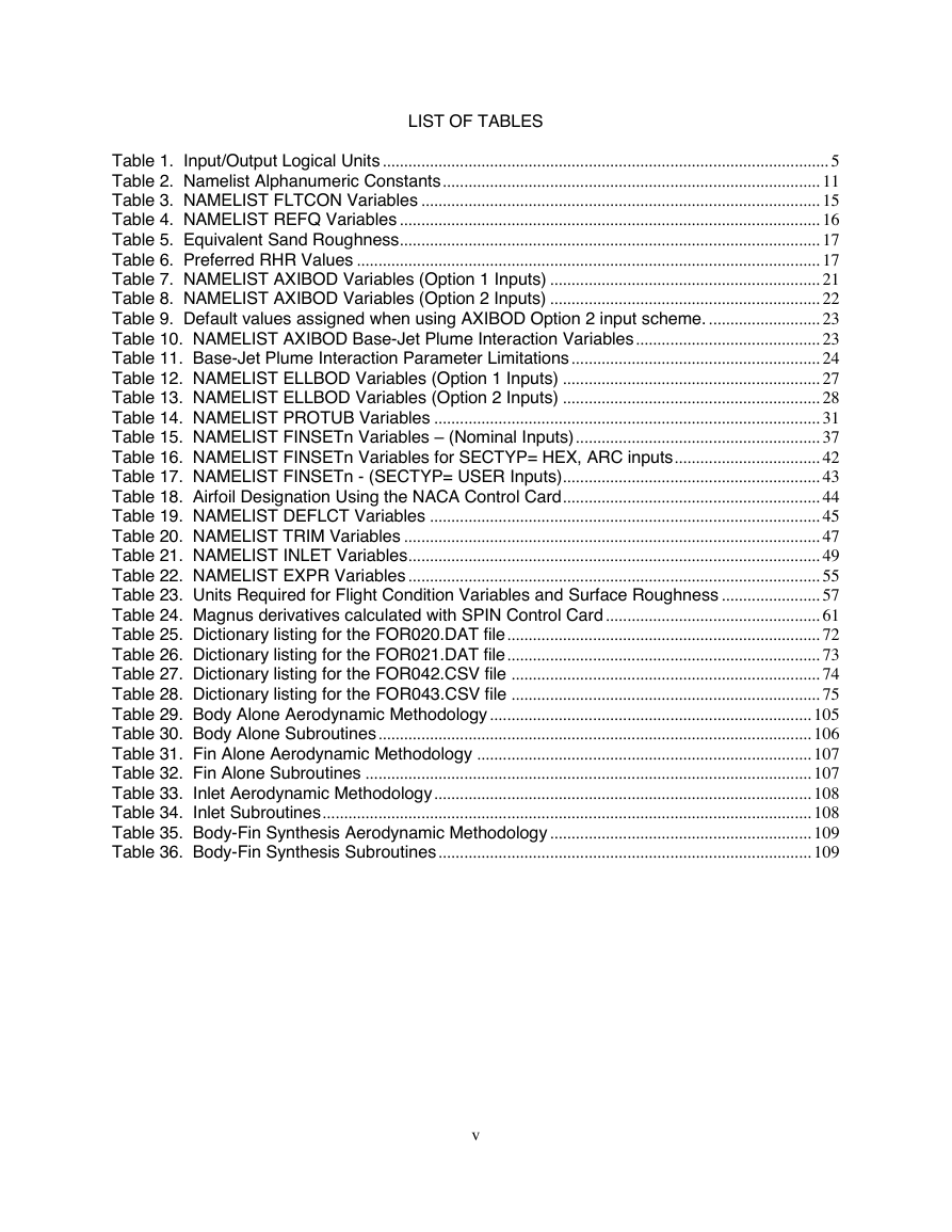
LIST OF TABLES
Table 1. Input/Output Logical Units ........................................................................................................ 5
Table 2. Namelist Alphanumeric Constants ........................................................................................ 11
Table 3. NAMELIST FLTCON Variables ............................................................................................. 15
Table 4. NAMELIST REFQ Variables .................................................................................................. 16
Table 5. Equivalent Sand Roughness.................................................................................................. 17
Table 6. Preferred RHR Values ............................................................................................................ 17
Table 7. NAMELIST AXIBOD Variables (Option 1 Inputs) ............................................................... 21
Table 8. NAMELIST AXIBOD Variables (Option 2 Inputs) ............................................................... 22
Table 9. Default values assigned when using AXIBOD Option 2 input scheme. .......................... 23
Table 10. NAMELIST AXIBOD Base-Jet Plume Interaction Variables ........................................... 23
Table 11. Base-Jet Plume Interaction Parameter Limitations .......................................................... 24
Table 12. NAMELIST ELLBOD Variables (Option 1 Inputs) ............................................................ 27
Table 13. NAMELIST ELLBOD Variables (Option 2 Inputs) ............................................................ 28
Table 14. NAMELIST PROTUB Variables .......................................................................................... 31
Table 15. NAMELIST FINSETn Variables – (Nominal Inputs) ......................................................... 37
Table 16. NAMELIST FINSETn Variables for SECTYP= HEX, ARC inputs .................................. 42
Table 17. NAMELIST FINSETn - (SECTYP= USER Inputs)............................................................ 43
Table 18. Airfoil Designation Using the NACA Control Card ............................................................ 44
Table 19. NAMELIST DEFLCT Variables ........................................................................................... 45
Table 20. NAMELIST TRIM Variables ................................................................................................. 47
Table 21. NAMELIST INLET Variables................................................................................................ 49
Table 22. NAMELIST EXPR Variables ................................................................................................ 55
Table 23. Units Required for Flight Condition Variables and Surface Roughness ....................... 57
Table 24. Magnus derivatives calculated with SPIN Control Card .................................................. 61
Table 25. Dictionary listing for the FOR020.DAT file ......................................................................... 72
Table 26. Dictionary listing for the FOR021.DAT file ......................................................................... 73
Table 27. Dictionary listing for the FOR042.CSV file ........................................................................ 74
Table 28. Dictionary listing for the FOR043.CSV file ........................................................................ 75
Table 29. Body Alone Aerodynamic Methodology ........................................................................... 105
Table 30. Body Alone Subroutines ..................................................................................................... 106
Table 31. Fin Alone Aerodynamic Methodology .............................................................................. 107
Table 32. Fin Alone Subroutines ........................................................................................................ 107
Table 33. Inlet Aerodynamic Methodology ........................................................................................ 108
Table 34. Inlet Subroutines .................................................................................................................. 108
Table 35. Body-Fin Synthesis Aerodynamic Methodology ............................................................. 109
Table 36. Body-Fin Synthesis Subroutines ....................................................................................... 109
v
�
PREFACE
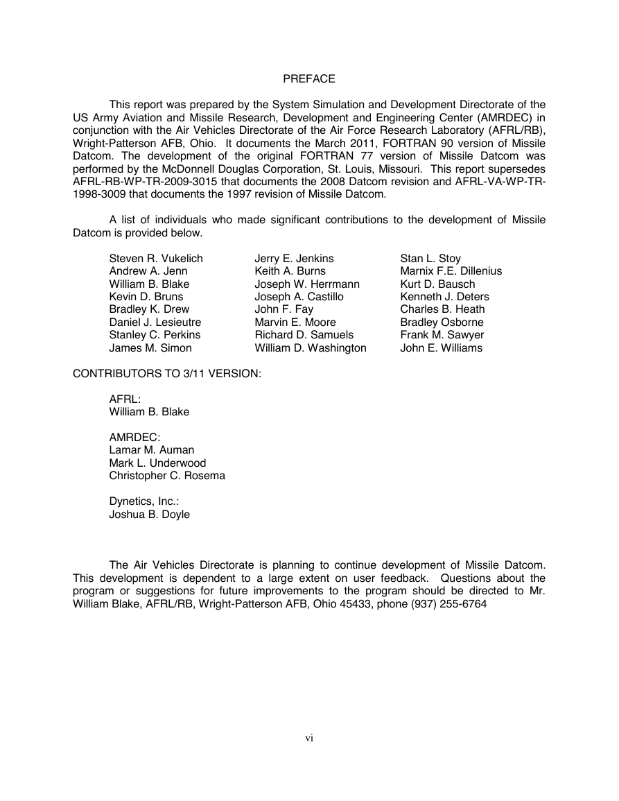
A list of individuals who made significant contributions to the development of Missile
This report was prepared by the System Simulation and Development Directorate of the
US Army Aviation and Missile Research, Development and Engineering Center (AMRDEC) in
conjunction with the Air Vehicles Directorate of the Air Force Research Laboratory (AFRL/RB),
Wright-Patterson AFB, Ohio. It documents the March 2011, FORTRAN 90 version of Missile
Datcom. The development of the original FORTRAN 77 version of Missile Datcom was
performed by the McDonnell Douglas Corporation, St. Louis, Missouri. This report supersedes
AFRL-RB-WP-TR-2009-3015 that documents the 2008 Datcom revision and AFRL-VA-WP-TR-
1998-3009 that documents the 1997 revision of Missile Datcom.
Datcom is provided below.
CONTRIBUTORS TO 3/11 VERSION:
Jerry E. Jenkins
Keith A. Burns
Joseph W. Herrmann
Joseph A. Castillo
John F. Fay
Marvin E. Moore
Richard D. Samuels
William D. Washington
Stan L. Stoy
Marnix F.E. Dillenius
Kurt D. Bausch
Kenneth J. Deters
Charles B. Heath
Bradley Osborne
Frank M. Sawyer
John E. Williams
Steven R. Vukelich
Andrew A. Jenn
William B. Blake
Kevin D. Bruns
Bradley K. Drew
Daniel J. Lesieutre
Stanley C. Perkins
James M. Simon
AFRL:
William B. Blake
AMRDEC:
Lamar M. Auman
Mark L. Underwood
Christopher C. Rosema
Dynetics, Inc.:
Joshua B. Doyle
The Air Vehicles Directorate is planning to continue development of Missile Datcom.
This development is dependent to a large extent on user feedback. Questions about the
program or suggestions for future improvements to the program should be directed to Mr.
William Blake, AFRL/RB, Wright-Patterson AFB, Ohio 45433, phone (937) 255-6764
vi
�



 2023年江西萍乡中考道德与法治真题及答案.doc
 2012年重庆南川中考生物真题及答案.doc
 2013年江西师范大学地理学综合及文艺理论基础考研真题.doc
 2020年四川甘孜小升初语文真题及答案I卷.doc
 2020年注册岩土工程师专业基础考试真题及答案.doc
 2023-2024学年福建省厦门市九年级上学期数学月考试题及答案.doc
 2021-2022学年辽宁省沈阳市大东区九年级上学期语文期末试题及答案.doc
 2022-2023学年北京东城区初三第一学期物理期末试卷及答案.doc
 2018上半年江西教师资格初中地理学科知识与教学能力真题及答案.doc
 2012年河北国家公务员申论考试真题及答案-省级.doc
 2020-2021学年江苏省扬州市江都区邵樊片九年级上学期数学第一次质量检测试题及答案.doc
 2022下半年黑龙江教师资格证中学综合素质真题及答案.doc