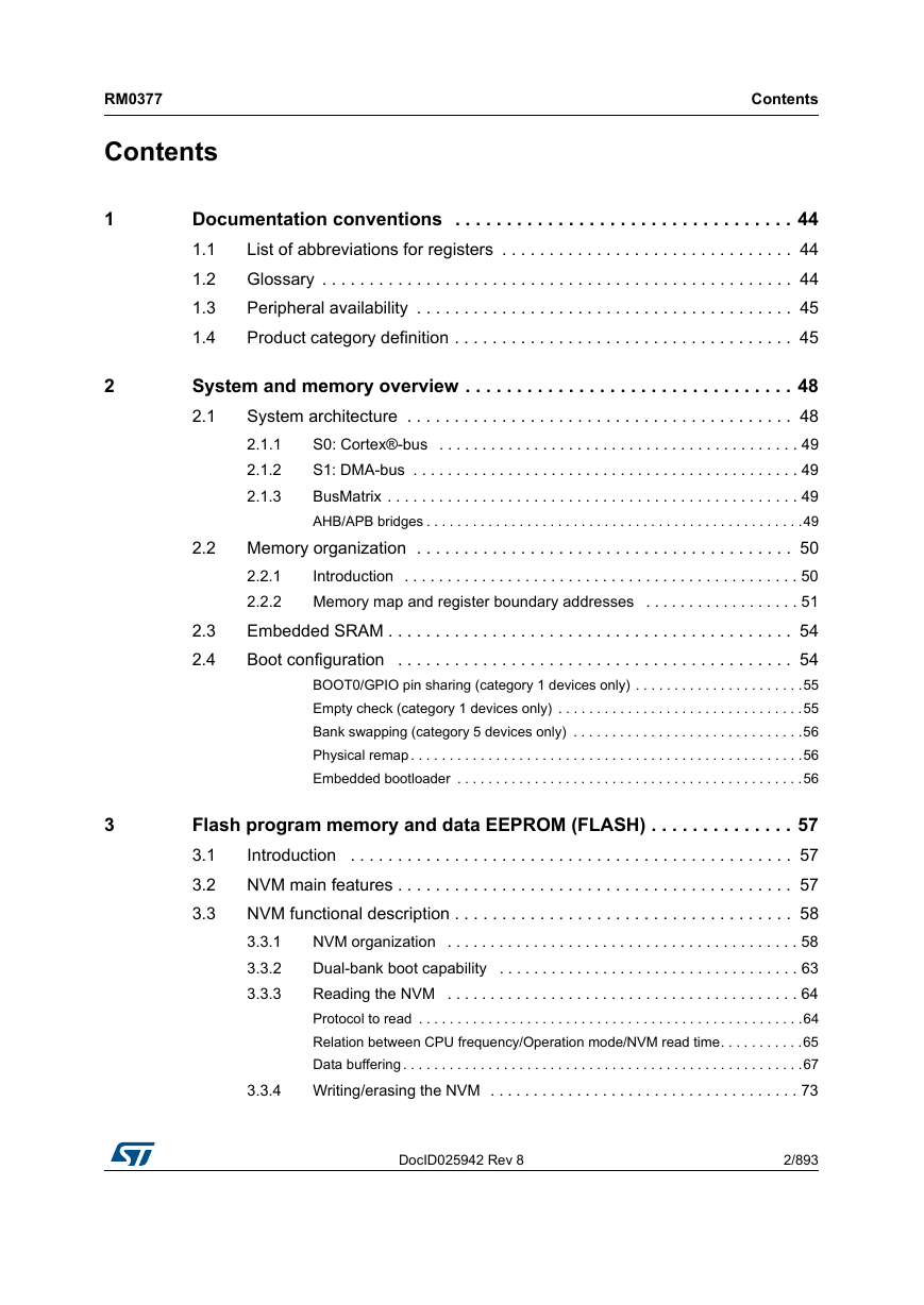
1 Documentation conventions
1.1 List of abbreviations for registers
1.2 Glossary
1.3 Peripheral availability
1.4 Product category definition
2 System and memory overview
2.1 System architecture
2.1.1 S0: Cortex®-bus
2.1.2 S1: DMA-bus
2.1.3 BusMatrix
2.2 Memory organization
2.2.1 Introduction
2.2.2 Memory map and register boundary addresses
2.3 Embedded SRAM
2.4 Boot configuration
3 Flash program memory and data EEPROM (FLASH)
3.1 Introduction
3.2 NVM main features
3.3 NVM functional description
3.3.1 NVM organization
3.3.2 Dual-bank boot capability
3.3.3 Reading the NVM
3.3.4 Writing/erasing the NVM
3.4 Memory protection
3.4.1 RDP (Read Out Protection)
3.4.2 PcROP (Proprietary Code Read-Out Protection)
3.4.3 Protections against unwanted write/erase operations
3.4.4 Write/erase protection management
3.4.5 Protection errors
3.5 NVM interrupts
3.5.1 Hard fault
3.6 Memory interface management
3.6.1 Operation priority and evolution
3.6.2 Sequence of operations
3.6.3 Change the number of wait states while reading
3.6.4 Power-down
3.7 Flash register description
3.7.1 Access control register (FLASH_ACR)
3.7.2 Program and erase control register (FLASH_PECR)
3.7.3 Power-down key register (FLASH_PDKEYR)
3.7.4 PECR unlock key register (FLASH_PEKEYR)
3.7.5 Program and erase key register (FLASH_PRGKEYR)
3.7.6 Option bytes unlock key register (FLASH_OPTKEYR)
3.7.7 Status register (FLASH_SR)
3.7.8 Option bytes register (FLASH_OPTR)
3.7.9 Write protection register 1 (FLASH_WRPROT1)
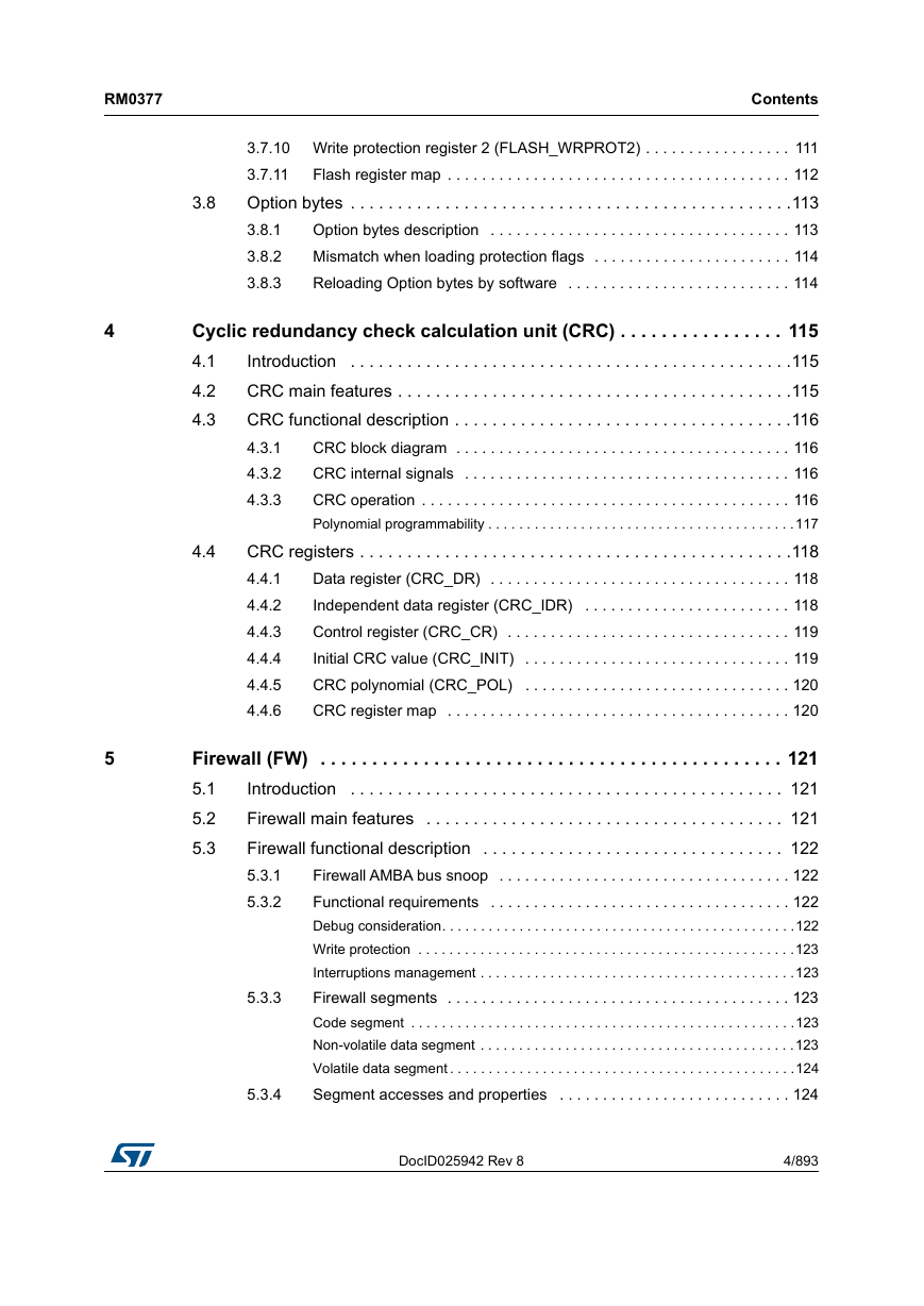
3.7.10 Write protection register 2 (FLASH_WRPROT2)
3.7.11 Flash register map
3.8 Option bytes
3.8.1 Option bytes description
3.8.2 Mismatch when loading protection flags
3.8.3 Reloading Option bytes by software
4 Cyclic redundancy check calculation unit (CRC)
4.1 Introduction
4.2 CRC main features
4.3 CRC functional description
4.3.1 CRC block diagram
4.3.2 CRC internal signals
4.3.3 CRC operation
4.4 CRC registers
4.4.1 Data register (CRC_DR)
4.4.2 Independent data register (CRC_IDR)
4.4.3 Control register (CRC_CR)
4.4.4 Initial CRC value (CRC_INIT)
4.4.5 CRC polynomial (CRC_POL)
4.4.6 CRC register map
5 Firewall (FW)
5.1 Introduction
5.2 Firewall main features
5.3 Firewall functional description
5.3.1 Firewall AMBA bus snoop
5.3.2 Functional requirements
5.3.3 Firewall segments
5.3.4 Segment accesses and properties
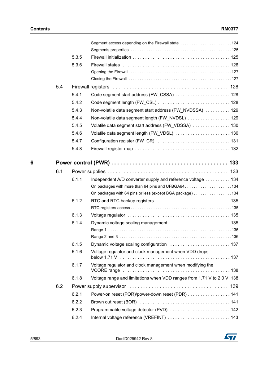
5.3.5 Firewall initialization
5.3.6 Firewall states
5.4 Firewall registers
5.4.1 Code segment start address (FW_CSSA)
5.4.2 Code segment length (FW_CSL)
5.4.3 Non-volatile data segment start address (FW_NVDSSA)
5.4.4 Non-volatile data segment length (FW_NVDSL)
5.4.5 Volatile data segment start address (FW_VDSSA)
5.4.6 Volatile data segment length (FW_VDSL)
5.4.7 Configuration register (FW_CR)
5.4.8 Firewall register map
6 Power control (PWR)
6.1 Power supplies
6.1.1 Independent A/D converter supply and reference voltage
6.1.2 RTC and RTC backup registers
6.1.3 Voltage regulator
6.1.4 Dynamic voltage scaling management
6.1.5 Dynamic voltage scaling configuration
6.1.6 Voltage regulator and clock management when VDD drops below 1.71 V
6.1.7 Voltage regulator and clock management when modifying the VCORE range
6.1.8 Voltage range and limitations when VDD ranges from 1.71 V to 2.0 V
6.2 Power supply supervisor
6.2.1 Power-on reset (POR)/power-down reset (PDR)
6.2.2 Brown out reset (BOR)
6.2.3 Programmable voltage detector (PVD)
6.2.4 Internal voltage reference (VREFINT)
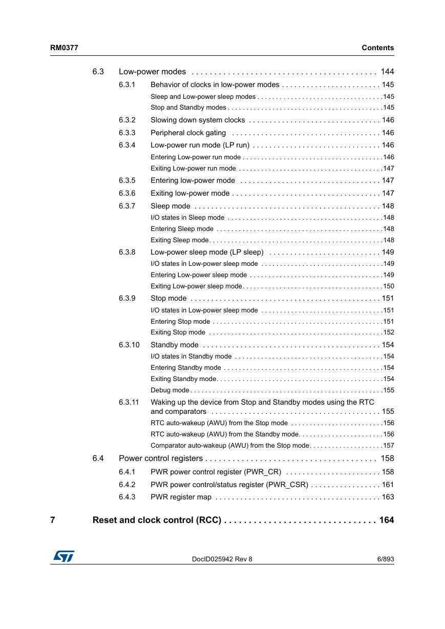
6.3 Low-power modes
6.3.1 Behavior of clocks in low-power modes
6.3.2 Slowing down system clocks
6.3.3 Peripheral clock gating
6.3.4 Low-power run mode (LP run)
6.3.5 Entering low-power mode
6.3.6 Exiting low-power mode
6.3.7 Sleep mode
6.3.8 Low-power sleep mode (LP sleep)
6.3.9 Stop mode
6.3.10 Standby mode
6.3.11 Waking up the device from Stop and Standby modes using the RTC and comparators
6.4 Power control registers
6.4.1 PWR power control register (PWR_CR)
6.4.2 PWR power control/status register (PWR_CSR)
6.4.3 PWR register map
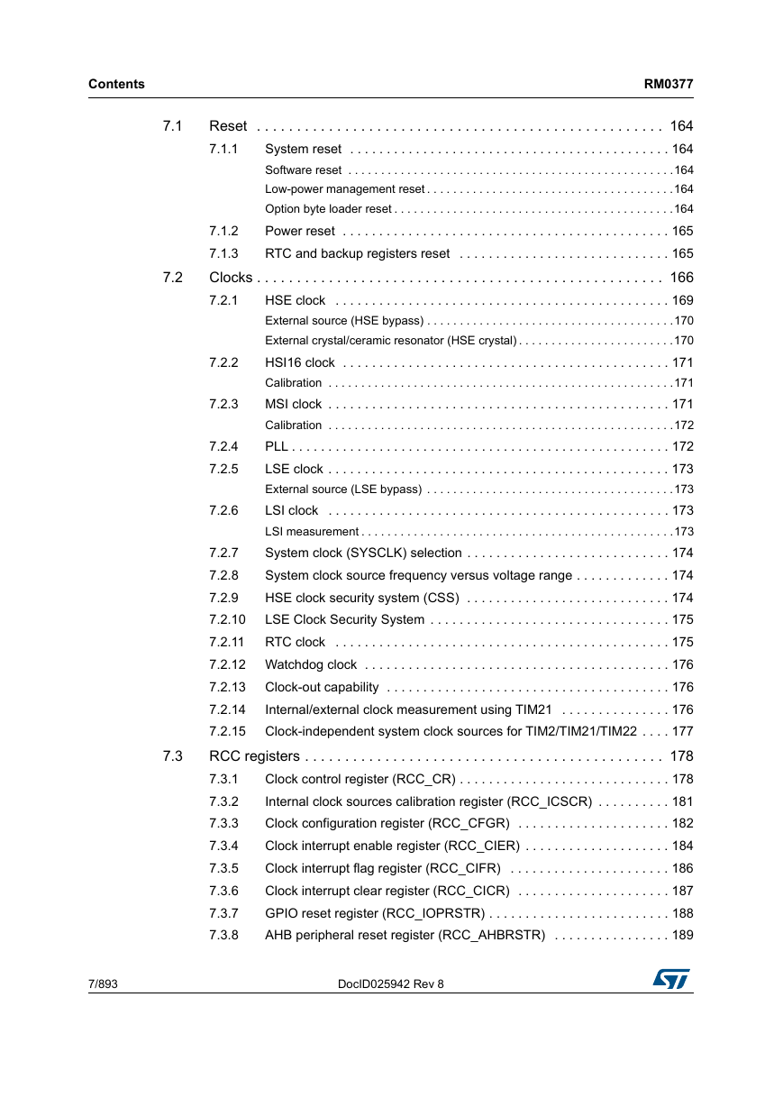
7 Reset and clock control (RCC)
7.1 Reset
7.1.1 System reset
7.1.2 Power reset
7.1.3 RTC and backup registers reset
7.2 Clocks
7.2.1 HSE clock
7.2.2 HSI16 clock
7.2.3 MSI clock
7.2.4 PLL
7.2.5 LSE clock
7.2.6 LSI clock
7.2.7 System clock (SYSCLK) selection
7.2.8 System clock source frequency versus voltage range
7.2.9 HSE clock security system (CSS)
7.2.10 LSE Clock Security System
7.2.11 RTC clock
7.2.12 Watchdog clock
7.2.13 Clock-out capability
7.2.14 Internal/external clock measurement using TIM21
7.2.15 Clock-independent system clock sources for TIM2/TIM21/TIM22
7.3 RCC registers
7.3.1 Clock control register (RCC_CR)
7.3.2 Internal clock sources calibration register (RCC_ICSCR)
7.3.3 Clock configuration register (RCC_CFGR)
7.3.4 Clock interrupt enable register (RCC_CIER)
7.3.5 Clock interrupt flag register (RCC_CIFR)
7.3.6 Clock interrupt clear register (RCC_CICR)
7.3.7 GPIO reset register (RCC_IOPRSTR)
7.3.8 AHB peripheral reset register (RCC_AHBRSTR)
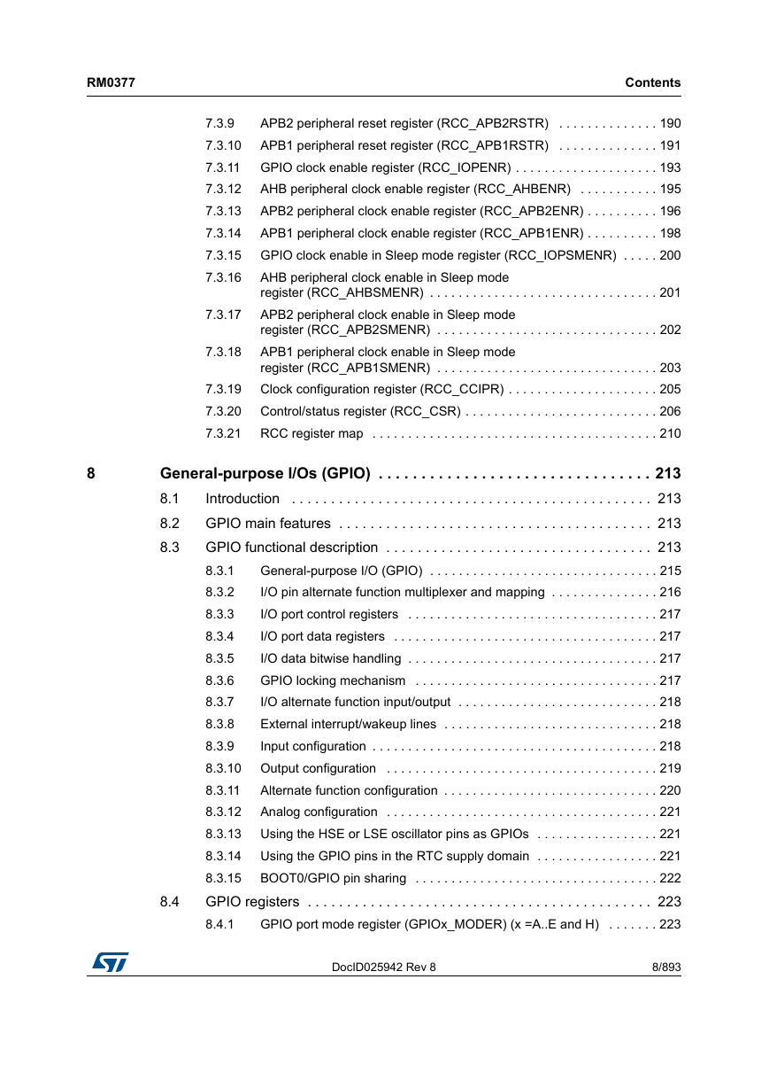
7.3.9 APB2 peripheral reset register (RCC_APB2RSTR)
7.3.10 APB1 peripheral reset register (RCC_APB1RSTR)
7.3.11 GPIO clock enable register (RCC_IOPENR)
7.3.12 AHB peripheral clock enable register (RCC_AHBENR)
7.3.13 APB2 peripheral clock enable register (RCC_APB2ENR)
7.3.14 APB1 peripheral clock enable register (RCC_APB1ENR)
7.3.15 GPIO clock enable in Sleep mode register (RCC_IOPSMENR)
7.3.16 AHB peripheral clock enable in Sleep mode register (RCC_AHBSMENR)
7.3.17 APB2 peripheral clock enable in Sleep mode register (RCC_APB2SMENR)
7.3.18 APB1 peripheral clock enable in Sleep mode register (RCC_APB1SMENR)
7.3.19 Clock configuration register (RCC_CCIPR)
7.3.20 Control/status register (RCC_CSR)
7.3.21 RCC register map
8 General-purpose I/Os (GPIO)
8.1 Introduction
8.2 GPIO main features
8.3 GPIO functional description
8.3.1 General-purpose I/O (GPIO)
8.3.2 I/O pin alternate function multiplexer and mapping
8.3.3 I/O port control registers
8.3.4 I/O port data registers
8.3.5 I/O data bitwise handling
8.3.6 GPIO locking mechanism
8.3.7 I/O alternate function input/output
8.3.8 External interrupt/wakeup lines
8.3.9 Input configuration
8.3.10 Output configuration
8.3.11 Alternate function configuration
8.3.12 Analog configuration
8.3.13 Using the HSE or LSE oscillator pins as GPIOs
8.3.14 Using the GPIO pins in the RTC supply domain
8.3.15 BOOT0/GPIO pin sharing
8.4 GPIO registers
8.4.1 GPIO port mode register (GPIOx_MODER) (x =A..E and H)
8.4.2 GPIO port output type register (GPIOx_OTYPER) (x = A..E and H)
8.4.3 GPIO port output speed register (GPIOx_OSPEEDR) (x = A..E and H)
8.4.4 GPIO port pull-up/pull-down register (GPIOx_PUPDR) (x = A..E and H)
8.4.5 GPIO port input data register (GPIOx_IDR) (x = A..E and H)
8.4.6 GPIO port output data register (GPIOx_ODR) (x = A..E and H)
8.4.7 GPIO port bit set/reset register (GPIOx_BSRR) (x = A..E and H)
8.4.8 GPIO port configuration lock register (GPIOx_LCKR) (x = A..E and H)
8.4.9 GPIO alternate function low register (GPIOx_AFRL) (x = A..E and H)
8.4.10 GPIO alternate function high register (GPIOx_AFRH) (x = A..E and H)
8.4.11 GPIO port bit reset register (GPIOx_BRR) (x = A..E and H)
8.4.12 GPIO register map
9 System configuration controller (SYSCFG)
9.1 Introduction
9.2 SYSCFG registers
9.2.1 SYSCFG memory remap register (SYSCFG_CFGR1)
9.2.2 SYSCFG peripheral mode configuration register (SYSCFG_CFGR2)
9.2.3 Reference control and status register (SYSCFG_CFGR3)
9.2.4 SYSCFG external interrupt configuration register 1 (SYSCFG_EXTICR1)
9.2.5 SYSCFG external interrupt configuration register 2 (SYSCFG_EXTICR2)
9.2.6 SYSCFG external interrupt configuration register 3 (SYSCFG_EXTICR3)
9.2.7 SYSCFG external interrupt configuration register 4 (SYSCFG_EXTICR4)
9.2.8 SYSCFG register map
10 Direct memory access controller (DMA)
10.1 Introduction
10.2 DMA main features
10.3 DMA functional description
10.3.1 DMA transactions
10.3.2 Arbiter
10.3.3 DMA channels
10.3.4 Programmable data width, data alignment and endianness
10.3.5 Error management
10.3.6 DMA interrupts
10.3.7 DMA request mapping
10.4 DMA registers
10.4.1 DMA interrupt status register (DMA_ISR)
10.4.2 DMA interrupt flag clear register (DMA_IFCR)
10.4.3 DMA channel x configuration register (DMA_CCRx) (x = 1..7 , where x = channel number)
10.4.4 DMA channel x number of data register (DMA_CNDTRx) (x = 1..7, where x = channel number)
10.4.5 DMA channel x peripheral address register (DMA_CPARx) (x = 1..7, where x = channel number)
10.4.6 DMA channel x memory address register (DMA_CMARx) (x = 1..7, where x = channel number)
10.4.7 DMA channel selection register (DMA_CSELR)
10.4.8 DMA register map
11 Nested vectored interrupt controller (NVIC)
11.1 Main features
11.2 SysTick calibration value register
11.3 Interrupt and exception vectors
12 Extended interrupt and event controller (EXTI)
12.1 Introduction
12.2 EXTI main features
12.3 EXTI functional description
12.3.1 EXTI block diagram
12.3.2 Wakeup event management
12.3.3 Peripherals asynchronous interrupts
12.3.4 Hardware interrupt selection
12.3.5 Hardware event selection
12.3.6 Software interrupt/event selection
12.4 EXTI interrupt/event line mapping
12.5 EXTI registers
12.5.1 EXTI interrupt mask register (EXTI_IMR)
12.5.2 EXTI event mask register (EXTI_EMR)
12.5.3 EXTI rising edge trigger selection register (EXTI_RTSR)
12.5.4 Falling edge trigger selection register (EXTI_FTSR)
12.5.5 EXTI software interrupt event register (EXTI_SWIER)
12.5.6 EXTI pending register (EXTI_PR)
12.5.7 EXTI register map
13 Analog-to-digital converter (ADC)
13.1 Introduction
13.2 ADC main features
13.3 ADC functional description
13.3.1 ADC pins and internal signals
13.3.2 ADC voltage regulator (ADVREGEN)
13.3.3 Calibration (ADCAL)
13.3.4 ADC on-off control (ADEN, ADDIS, ADRDY)
13.3.5 ADC clock (CKMODE, PRESC[3:0], LFMEN)
13.3.6 Configuring the ADC
13.3.7 Channel selection (CHSEL, SCANDIR)
13.3.8 Programmable sampling time (SMP)
13.3.9 Single conversion mode (CONT=0)
13.3.10 Continuous conversion mode (CONT=1)
13.3.11 Starting conversions (ADSTART)
13.3.12 Timings
13.3.13 Stopping an ongoing conversion (ADSTP)
13.4 Conversion on external trigger and trigger polarity (EXTSEL, EXTEN)
13.4.1 Discontinuous mode (DISCEN)
13.4.2 Programmable resolution (RES) - fast conversion mode
13.4.3 End of conversion, end of sampling phase (EOC, EOSMP flags)
13.4.4 End of conversion sequence (EOS flag)
13.4.5 Example timing diagrams (single/continuous modes hardware/software triggers)
13.5 Data management
13.5.1 Data register and data alignment (ADC_DR, ALIGN)
13.5.2 ADC overrun (OVR, OVRMOD)
13.5.3 Managing a sequence of data converted without using the DMA
13.5.4 Managing converted data without using the DMA without overrun
13.5.5 Managing converted data using the DMA
13.6 Low-power features
13.6.1 Wait mode conversion
13.6.2 Auto-off mode (AUTOFF)
13.7 Analog window watchdog (AWDEN, AWDSGL, AWDCH, ADC_TR, AWD)
13.8 Oversampler
13.8.1 ADC operating modes supported when oversampling
13.8.2 Analog watchdog
13.8.3 Triggered mode
13.9 Temperature sensor and internal reference voltage
13.10 VLCD voltage monitoring
13.11 ADC interrupts
13.12 ADC registers
13.12.1 ADC interrupt and status register (ADC_ISR)
13.12.2 ADC interrupt enable register (ADC_IER)
13.12.3 ADC control register (ADC_CR)
13.12.4 ADC configuration register 1 (ADC_CFGR1)
13.12.5 ADC configuration register 2 (ADC_CFGR2)
13.12.6 ADC sampling time register (ADC_SMPR)
13.12.7 ADC watchdog threshold register (ADC_TR)
13.12.8 ADC channel selection register (ADC_CHSELR)
13.12.9 ADC data register (ADC_DR)
13.12.10 ADC Calibration factor (ADC_CALFACT)
13.12.11 ADC common configuration register (ADC_CCR)
13.12.12 ADC register map
14 Comparator (COMP)
14.1 Introduction
14.2 COMP main features
14.3 COMP functional description
14.3.1 COMP block diagram
14.3.2 COMP pins and internal signals
14.3.3 COMP reset and clocks
14.3.4 Comparator LOCK mechanism
14.3.5 Power mode
14.4 COMP interrupts
14.5 COMP registers
14.5.1 Comparator 1 control and status register (COMP1_CSR)
14.5.2 Comparator 2 control and status register (COMP2_CSR)
14.5.3 COMP register map
15 AES hardware accelerator (AES)
15.1 Introduction
15.2 AES main features
15.3 AES implementation
15.4 AES functional description
15.4.1 AES block diagram
15.4.2 AES internal signals
15.4.3 AES cryptographic core
15.4.4 AES procedure to perform a cipher operation
15.4.5 AES decryption key preparation
15.4.6 AES ciphertext stealing and data padding
15.4.7 AES task suspend and resume
15.4.8 AES basic chaining modes (ECB, CBC)
15.4.9 AES counter (CTR) mode
15.4.10 AES data registers and data swapping
15.4.11 AES key registers
15.4.12 AES initialization vector registers
15.4.13 AES DMA interface
15.4.14 AES error management
15.5 AES interrupts
15.6 AES processing latency
15.7 AES registers
15.7.1 AES control register (AES_CR)
15.7.2 AES status register (AES_SR)
15.7.3 AES data input register (AES_DINR)
15.7.4 AES data output register (AES_DOUTR)
15.7.5 AES key register 0 (AES_KEYR0)
15.7.6 AES key register 1 (AES_KEYR1)
15.7.7 AES key register 2 (AES_KEYR2)
15.7.8 AES key register 3 (AES_KEYR3)
15.7.9 AES initialization vector register 0 (AES_IVR0)
15.7.10 AES initialization vector register 1 (AES_IVR1)
15.7.11 AES initialization vector register 2 (AES_IVR2)
15.7.12 AES initialization vector register 3 (AES_IVR3)
15.7.13 AES register map
16 General-purpose timers (TIM2/TIM3)
16.1 TIM2/TIM3 introduction
16.2 TIM2/TIM3 main features
16.3 TIM2/TIM3 functional description
16.3.1 Time-base unit
16.3.2 Counter modes
16.3.3 Clock selection
16.3.4 Capture/compare channels
16.3.5 Input capture mode
16.3.6 PWM input mode
16.3.7 Forced output mode
16.3.8 Output compare mode
16.3.9 PWM mode
16.3.10 One-pulse mode
16.3.11 Clearing the OCxREF signal on an external event
16.3.12 Encoder interface mode
16.3.13 Timer input XOR function
16.3.14 Timers and external trigger synchronization
16.3.15 Timer synchronization
16.3.16 Debug mode
16.4 TIM2/TIM3 registers
16.4.1 TIMx control register 1 (TIMx_CR1)
16.4.2 TIMx control register 2 (TIMx_CR2)
16.4.3 TIMx slave mode control register (TIMx_SMCR)
16.4.4 TIMx DMA/Interrupt enable register (TIMx_DIER)
16.4.5 TIMx status register (TIMx_SR)
16.4.6 TIMx event generation register (TIMx_EGR)
16.4.7 TIMx capture/compare mode register 1 (TIMx_CCMR1)
16.4.8 TIMx capture/compare mode register 2 (TIMx_CCMR2)
16.4.9 TIMx capture/compare enable register (TIMx_CCER)
16.4.10 TIMx counter (TIMx_CNT)
16.4.11 TIMx prescaler (TIMx_PSC)
16.4.12 TIMx auto-reload register (TIMx_ARR)
16.4.13 TIMx capture/compare register 1 (TIMx_CCR1)
16.4.14 TIMx capture/compare register 2 (TIMx_CCR2)
16.4.15 TIMx capture/compare register 3 (TIMx_CCR3)
16.4.16 TIMx capture/compare register 4 (TIMx_CCR4)
16.4.17 TIMx DMA control register (TIMx_DCR)
16.4.18 TIMx DMA address for full transfer (TIMx_DMAR)
16.4.19 TIM2 option register (TIM2_OR)
16.4.20 TIM3 option register (TIM3_OR)
16.5 TIMx register map
17 General-purpose timers (TIM21/22)
17.1 Introduction
17.2 TIM21/22 main features
17.2.1 TIM21/22 main features
17.3 TIM21/22 functional description
17.3.1 Timebase unit
17.3.2 Counter modes
17.3.3 Clock selection
17.3.4 Capture/compare channels
17.3.5 Input capture mode
17.3.6 PWM input mode
17.3.7 Forced output mode
17.3.8 Output compare mode
17.3.9 PWM mode
17.3.10 Clearing the OCxREF signal on an external event
17.3.11 One-pulse mode
17.3.12 Encoder interface mode
17.3.13 TIM21/22 external trigger synchronization
17.3.14 Timer synchronization (TIM21/22)
17.3.15 Debug mode
17.4 TIM21/22 registers
17.4.1 TIM21/22 control register 1 (TIMx_CR1)
17.4.2 TIM21/22 control register 2 (TIMx_CR2)
17.4.3 TIM21/22 slave mode control register (TIMx_SMCR)
17.4.4 TIM21/22 Interrupt enable register (TIMx_DIER)
17.4.5 TIM21/22 status register (TIMx_SR)
17.4.6 TIM21/22 event generation register (TIMx_EGR)
17.4.7 TIM21/22 capture/compare mode register 1 (TIMx_CCMR1)
17.4.8 TIM21/22 capture/compare enable register (TIMx_CCER)
17.4.9 TIM21/22 counter (TIMx_CNT)
17.4.10 TIM21/22 prescaler (TIMx_PSC)
17.4.11 TIM21/22 auto-reload register (TIMx_ARR)
17.4.12 TIM21/22 capture/compare register 1 (TIMx_CCR1)
17.4.13 TIM21/22 capture/compare register 2 (TIMx_CCR2)
17.4.14 TIM21 option register (TIM21_OR)
17.4.15 TIM22 option register (TIM22_OR)
17.4.16 TIM21/22 register map
18 Basic timers (TIM6/7)
18.1 Introduction
18.2 TIM6/7 main features
18.3 TIM6/7 functional description
18.3.1 Time-base unit
18.3.2 Counting mode
18.3.3 Clock source
18.3.4 Debug mode
18.4 TIM6/7 registers
18.4.1 TIM6/7 control register 1 (TIMx_CR1)
18.4.2 TIM6/7 control register 2 (TIMx_CR2)
18.4.3 TIM6/7 DMA/Interrupt enable register (TIMx_DIER)
18.4.4 TIM6/7 status register (TIMx_SR)
18.4.5 TIM6/7 event generation register (TIMx_EGR)
18.4.6 TIM6/7 counter (TIMx_CNT)
18.4.7 TIM6/7 prescaler (TIMx_PSC)
18.4.8 TIM6/7 auto-reload register (TIMx_ARR)
18.4.9 TIM6/7 register map
19 Low-power timer (LPTIM)
19.1 Introduction
19.2 LPTIM main features
19.3 LPTIM implementation
19.4 LPTIM functional description
19.4.1 LPTIM block diagram
19.4.2 LPTIM trigger mapping
19.4.3 LPTIM reset and clocks
19.4.4 Glitch filter
19.4.5 Prescaler
19.4.6 Trigger multiplexer
19.4.7 Operating mode
19.4.8 Timeout function
19.4.9 Waveform generation
19.4.10 Register update
19.4.11 Counter mode
19.4.12 Timer enable
19.4.13 Encoder mode
19.5 LPTIM interrupts
19.6 LPTIM registers
19.6.1 LPTIM interrupt and status register (LPTIM_ISR)
19.6.2 LPTIM interrupt clear register (LPTIM_ICR)
19.6.3 LPTIM interrupt enable register (LPTIM_IER)
19.6.4 LPTIM configuration register (LPTIM_CFGR)
19.6.5 LPTIM control register (LPTIM_CR)
19.6.6 LPTIM compare register (LPTIM_CMP)
19.6.7 LPTIM autoreload register (LPTIM_ARR)
19.6.8 LPTIM counter register (LPTIM_CNT)
19.6.9 LPTIM register map
20 Independent watchdog (IWDG)
20.1 Introduction
20.2 IWDG main features
20.3 IWDG functional description
20.3.1 IWDG block diagram
20.3.2 Window option
20.3.3 Hardware watchdog
20.3.4 Behavior in Stop and Standby modes
20.3.5 Register access protection
20.3.6 Debug mode
20.4 IWDG registers
20.4.1 Key register (IWDG_KR)
20.4.2 Prescaler register (IWDG_PR)
20.4.3 Reload register (IWDG_RLR)
20.4.4 Status register (IWDG_SR)
20.4.5 Window register (IWDG_WINR)
20.4.6 IWDG register map
21 System window watchdog (WWDG)
21.1 Introduction
21.2 WWDG main features
21.3 WWDG functional description
21.3.1 Enabling the watchdog
21.3.2 Controlling the downcounter
21.3.3 Advanced watchdog interrupt feature
21.3.4 How to program the watchdog timeout
21.3.5 Debug mode
21.4 WWDG registers
21.4.1 Control register (WWDG_CR)
21.4.2 Configuration register (WWDG_CFR)
21.4.3 Status register (WWDG_SR)
21.4.4 WWDG register map
22 Real-time clock (RTC)
22.1 Introduction
22.2 RTC main features
22.3 RTC implementation
22.4 RTC functional description
22.4.1 RTC block diagram
22.4.2 GPIOs controlled by the RTC
22.4.3 Clock and prescalers
22.4.4 Real-time clock and calendar
22.4.5 Programmable alarms
22.4.6 Periodic auto-wakeup
22.4.7 RTC initialization and configuration
22.4.8 Reading the calendar
22.4.9 Resetting the RTC
22.4.10 RTC synchronization
22.4.11 RTC reference clock detection
22.4.12 RTC smooth digital calibration
22.4.13 Time-stamp function
22.4.14 Tamper detection
22.4.15 Calibration clock output
22.4.16 Alarm output
22.5 RTC low-power modes
22.6 RTC interrupts
22.7 RTC registers
22.7.1 RTC time register (RTC_TR)
22.7.2 RTC date register (RTC_DR)
22.7.3 RTC control register (RTC_CR)
22.7.4 RTC initialization and status register (RTC_ISR)
22.7.5 RTC prescaler register (RTC_PRER)
22.7.6 RTC wakeup timer register (RTC_WUTR)
22.7.7 RTC alarm A register (RTC_ALRMAR)
22.7.8 RTC alarm B register (RTC_ALRMBR)
22.7.9 RTC write protection register (RTC_WPR)
22.7.10 RTC sub second register (RTC_SSR)
22.7.11 RTC shift control register (RTC_SHIFTR)
22.7.12 RTC timestamp time register (RTC_TSTR)
22.7.13 RTC timestamp date register (RTC_TSDR)
22.7.14 RTC time-stamp sub second register (RTC_TSSSR)
22.7.15 RTC calibration register (RTC_CALR)
22.7.16 RTC tamper configuration register (RTC_TAMPCR)
22.7.17 RTC alarm A sub second register (RTC_ALRMASSR)
22.7.18 RTC alarm B sub second register (RTC_ALRMBSSR)
22.7.19 RTC option register (RTC_OR)
22.7.20 RTC backup registers (RTC_BKPxR)
22.7.21 RTC register map
23 Inter-integrated circuit (I2C) interface
23.1 Introduction
23.2 I2C main features
23.3 I2C implementation
23.4 I2C functional description
23.4.1 I2C1/3 block diagram
23.4.2 I2C2 block diagram
23.4.3 I2C clock requirements
23.4.4 Mode selection
23.4.5 I2C initialization
23.4.6 Software reset
23.4.7 Data transfer
23.4.8 I2C slave mode
23.4.9 I2C master mode
23.4.10 I2C_TIMINGR register configuration examples
23.4.11 SMBus specific features
23.4.12 SMBus initialization
23.4.13 SMBus: I2C_TIMEOUTR register configuration examples
23.4.14 SMBus slave mode
23.4.15 Wakeup from Stop mode on address match
23.4.16 Error conditions
23.4.17 DMA requests
23.4.18 Debug mode
23.5 I2C low-power modes
23.6 I2C interrupts
23.7 I2C registers
23.7.1 Control register 1 (I2C_CR1)
23.7.2 Control register 2 (I2C_CR2)
23.7.3 Own address 1 register (I2C_OAR1)
23.7.4 Own address 2 register (I2C_OAR2)
23.7.5 Timing register (I2C_TIMINGR)
23.7.6 Timeout register (I2C_TIMEOUTR)
23.7.7 Interrupt and status register (I2C_ISR)
23.7.8 Interrupt clear register (I2C_ICR)
23.7.9 PEC register (I2C_PECR)
23.7.10 Receive data register (I2C_RXDR)
23.7.11 Transmit data register (I2C_TXDR)
23.7.12 I2C register map
24 Universal synchronous asynchronous receiver transmitter (USART)
24.1 Introduction
24.2 USART main features
24.3 USART extended features
24.4 USART implementation
24.5 USART functional description
24.5.1 USART character description
24.5.2 USART transmitter
24.5.3 USART receiver
24.5.4 USART baud rate generation
24.5.5 Tolerance of the USART receiver to clock deviation
24.5.6 USART auto baud rate detection
24.5.7 Multiprocessor communication using USART
24.5.8 Modbus communication using USART
24.5.9 USART parity control
24.5.10 USART LIN (local interconnection network) mode
24.5.11 USART synchronous mode
24.5.12 USART Single-wire Half-duplex communication
24.5.13 USART Smartcard mode
24.5.14 USART IrDA SIR ENDEC block
24.5.15 USART continuous communication in DMA mode
24.5.16 RS232 hardware flow control and RS485 driver enable using USART
24.5.17 Wakeup from Stop mode using USART
24.6 USART low-power modes
24.7 USART interrupts
24.8 USART registers
24.8.1 Control register 1 (USART_CR1)
24.8.2 Control register 2 (USART_CR2)
24.8.3 Control register 3 (USART_CR3)
24.8.4 Baud rate register (USART_BRR)
24.8.5 Guard time and prescaler register (USART_GTPR)
24.8.6 Receiver timeout register (USART_RTOR)
24.8.7 Request register (USART_RQR)
24.8.8 Interrupt and status register (USART_ISR)
24.8.9 Interrupt flag clear register (USART_ICR)
24.8.10 Receive data register (USART_RDR)
24.8.11 Transmit data register (USART_TDR)
24.8.12 USART register map
25 Low-power universal asynchronous receiver transmitter (LPUART)
25.1 Introduction
25.2 LPUART main features
25.3 LPUART implementation
25.4 LPUART functional description
25.4.1 LPUART character description
25.4.2 LPUART transmitter
25.4.3 LPUART receiver
25.4.4 LPUART baud rate generation
25.4.5 Tolerance of the LPUART receiver to clock deviation
25.4.6 Multiprocessor communication using LPUART
25.4.7 LPUART parity control
25.4.8 Single-wire Half-duplex communication using LPUART
25.4.9 Continuous communication in DMA mode using LPUART
25.4.10 RS232 Hardware flow control and RS485 Driver Enable using LPUART
25.4.11 Wakeup from Stop mode using LPUART
25.5 LPUART low-power mode
25.6 LPUART interrupts
25.7 LPUART registers
25.7.1 Control register 1 (LPUART_CR1)
25.7.2 Control register 2 (LPUART_CR2)
25.7.3 Control register 3 (LPUART_CR3)
25.7.4 Baud rate register (LPUART_BRR)
25.7.5 Request register (LPUART_RQR)
25.7.6 Interrupt & status register (LPUART_ISR)
25.7.7 Interrupt flag clear register (LPUART_ICR)
25.7.8 Receive data register (LPUART_RDR)
25.7.9 Transmit data register (LPUART_TDR)
25.7.10 LPUART register map
26 Serial peripheral interface/ inter-IC sound (SPI/I2S)
26.1 Introduction
26.1.1 SPI main features
26.1.2 SPI extended features
26.1.3 I2S features
26.2 SPI/I2S implementation
26.3 SPI functional description
26.3.1 General description
26.3.2 Communications between one master and one slave
26.3.3 Standard multi-slave communication
26.3.4 Multi-master communication
26.3.5 Slave select (NSS) pin management
26.3.6 Communication formats
26.3.7 SPI configuration
26.3.8 Procedure for enabling SPI
26.3.9 Data transmission and reception procedures
26.3.10 Procedure for disabling the SPI
26.3.11 Communication using DMA (direct memory addressing)
26.3.12 SPI status flags
26.3.13 SPI error flags
26.4 SPI special features
26.4.1 TI mode
26.4.2 CRC calculation
26.5 SPI interrupts
26.6 I2S functional description
26.6.1 I2S general description
26.6.2 I2S full-duplex
26.6.3 Supported audio protocols
26.6.4 Clock generator
26.6.5 I2S master mode
26.6.6 I2S slave mode
26.6.7 I2S status flags
26.6.8 I2S error flags
26.6.9 I2S interrupts
26.6.10 DMA features
26.7 SPI and I2S registers
26.7.1 SPI control register 1 (SPI_CR1) (not used in I2S mode)
26.7.2 SPI control register 2 (SPI_CR2)
26.7.3 SPI status register (SPI_SR)
26.7.4 SPI data register (SPI_DR)
26.7.5 SPI CRC polynomial register (SPI_CRCPR) (not used in I2S mode)
26.7.6 SPI RX CRC register (SPI_RXCRCR) (not used in I2S mode)
26.7.7 SPI TX CRC register (SPI_TXCRCR) (not used in I2S mode)
26.7.8 SPI_I2S configuration register (SPI_I2SCFGR)
26.7.9 SPI_I2S prescaler register (SPI_I2SPR)
26.7.10 SPI register map
27 Debug support (DBG)
27.1 Overview
27.2 Reference Arm® documentation
27.3 Pinout and debug port pins
27.3.1 SWD port pins
27.3.2 SW-DP pin assignment
27.3.3 Internal pull-up & pull-down on SWD pins
27.4 ID codes and locking mechanism
27.4.1 MCU device ID code
27.5 SWD port
27.5.1 SWD protocol introduction
27.5.2 SWD protocol sequence
27.5.3 SW-DP state machine (reset, idle states, ID code)
27.5.4 DP and AP read/write accesses
27.5.5 SW-DP registers
27.5.6 SW-AP registers
27.6 Core debug
27.7 BPU (Break Point Unit)
27.7.1 BPU functionality
27.8 DWT (Data Watchpoint)
27.8.1 DWT functionality
27.8.2 DWT Program Counter Sample Register
27.9 MCU debug component (DBG)
27.9.1 Debug support for low-power modes
27.9.2 Debug support for timers, watchdog and I2C
27.9.3 Debug MCU configuration register (DBG_CR)
27.9.4 Debug MCU APB1 freeze register (DBG_APB1_FZ)
27.9.5 Debug MCU APB2 freeze register (DBG_APB2_FZ)
27.10 DBG register map
28 Device electronic signature
28.1 Memory size register
28.1.1 Flash size register
28.2 Unique device ID registers (96 bits)
Appendix A Code examples
A.1 Introduction
A.2 NVM/RCC Operation code example
A.2.1 Increasing the CPU frequency preparation sequence code
A.2.2 Decreasing the CPU frequency preparation sequence code
A.2.3 Switch from PLL to HSI16 sequence code
A.2.4 Switch to PLL sequence code
A.3 NVM Operation code example
A.3.1 Unlocking the data EEPROM and FLASH_PECR register code example
A.3.2 Locking data EEPROM and FLASH_PECR register code example
A.3.3 Unlocking the NVM program memory code example
A.3.4 Unlocking the option bytes area code example
A.3.5 Write to data EEPROM code example
A.3.6 Erase to data EEPROM code example
A.3.7 Program Option byte code example
A.3.8 Erase Option byte code example
A.3.9 Program a single word to Flash program memory code example
A.3.10 Program half-page to Flash program memory code example
A.3.11 Erase a page in Flash program memory code example
A.3.12 Mass erase code example
A.4 Clock Controller
A.4.1 HSE start sequence code example
A.4.2 PLL configuration modification code example
A.4.3 MCO selection code example
A.5 GPIOs
A.5.1 Locking mechanism code example
A.5.2 Alternate function selection sequence code example
A.5.3 Analog GPIO configuration code example
A.6 DMA
A.6.1 DMA Channel Configuration sequence code example
A.7 Interrupts and event
A.7.1 NVIC initialization example
A.7.2 Extended interrupt selection code example
A.8 ADC
A.8.1 Calibration code example
A.8.2 ADC enable sequence code example
A.8.3 ADC disable sequence code example
A.8.4 ADC clock selection code example
A.8.5 Single conversion sequence code example - Software trigger
A.8.6 Continuous conversion sequence code example - Software trigger
A.8.7 Single conversion sequence code example - Hardware trigger
A.8.8 Continuous conversion sequence code example - Hardware trigger
A.8.9 DMA one shot mode sequence code example
A.8.10 DMA circular mode sequence code example
A.8.11 Wait mode sequence code example
A.8.12 Auto off and no wait mode sequence code example
A.8.13 Auto off and wait mode sequence code example
A.8.14 Analog watchdog code example
A.8.15 Oversampling code example
A.8.16 Temperature configuration code example
A.8.17 Temperature computation code example
A.9 Timers
A.9.1 Upcounter on TI2 rising edge code example
A.9.2 Up counter on each 2 ETR rising edges code example
A.9.3 Input capture configuration code example
A.9.4 Input capture data management code example
A.9.5 PWM input configuration code example
A.9.6 PWM input with DMA configuration code example
A.9.7 Output compare configuration code example
A.9.8 Edge-aligned PWM configuration example
A.9.9 Center-aligned PWM configuration example
A.9.10 ETR configuration to clear OCxREF code example
A.9.11 Encoder interface code example
A.9.12 Reset mode code example
A.9.13 Gated mode code example
A.9.14 Trigger mode code example
A.9.15 External clock mode 2 + trigger mode code example
A.9.16 One-Pulse mode code example
A.9.17 Timer prescaling another timer code example
A.9.18 Timer enabling another timer code example
A.9.19 Master and slave synchronization code example
A.9.20 Two timers synchronized by an external trigger code example
A.9.21 DMA burst feature code example
A.10 Low-power timer (LPTIM)
A.10.1 Pulse counter configuration code example
A.11 IWDG code example
A.11.1 IWDG configuration code example
A.11.2 IWDG configuration with window code example
A.12 WWDG code example
A.12.1 WWDG configuration code example
A.13 RTC code example
A.13.1 RTC calendar configuration code example
A.13.2 RTC alarm configuration code example
A.13.3 RTC WUT configuration code example
A.13.4 RTC read calendar code example
A.13.5 RTC calibration code example
A.13.6 RTC tamper and time stamp configuration code example
A.13.7 RTC tamper and time stamp code example
A.13.8 RTC clock output code example
A.14 I2C code example
A.14.1 I2C configured in slave mode code example
A.14.2 I2C slave transmitter code example
A.14.3 I2C slave receiver code example
A.14.4 I2C configured in master mode to receive code example
A.14.5 I2C configured in master mode to transmit code example
A.14.6 I2C master transmitter code example
A.14.7 I2C master receiver code example
A.14.8 I2C configured in master mode to transmit with DMA code example
A.14.9 I2C configured in slave mode to receive with DMA code example
A.15 USART code example
A.15.1 USART transmitter configuration code example
A.15.2 USART transmit byte code example
A.15.3 USART transfer complete code example
A.15.4 USART receiver configuration code example
A.15.5 USART receive byte code example
A.15.6 USART LIN mode code example
A.15.7 USART synchronous mode code example
A.15.8 USART single-wire half-duplex code example
A.15.9 USART smartcard mode code example
A.15.10 USART IrDA mode code example
A.15.11 USART DMA code example
A.15.12 USART hardware flow control code example
A.16 LPUART code example
A.16.1 LPUART receiver configuration code example
A.16.2 LPUART receive byte code example
A.17 SPI code example
A.17.1 SPI master configuration code example
A.17.2 SPI slave configuration code example
A.17.3 SPI full duplex communication code example
A.17.4 SPI master configuration with DMA code example
A.17.5 SPI slave configuration with DMA code example
A.17.6 SPI interrupt code example
A.18 DBG code example
A.18.1 DBG read device Id code example
A.18.2 DBG debug in LPM code example
Revision history



 2023年江西萍乡中考道德与法治真题及答案.doc
 2012年重庆南川中考生物真题及答案.doc
 2013年江西师范大学地理学综合及文艺理论基础考研真题.doc
 2020年四川甘孜小升初语文真题及答案I卷.doc
 2020年注册岩土工程师专业基础考试真题及答案.doc
 2023-2024学年福建省厦门市九年级上学期数学月考试题及答案.doc
 2021-2022学年辽宁省沈阳市大东区九年级上学期语文期末试题及答案.doc
 2022-2023学年北京东城区初三第一学期物理期末试卷及答案.doc
 2018上半年江西教师资格初中地理学科知识与教学能力真题及答案.doc
 2012年河北国家公务员申论考试真题及答案-省级.doc
 2020-2021学年江苏省扬州市江都区邵樊片九年级上学期数学第一次质量检测试题及答案.doc
 2022下半年黑龙江教师资格证中学综合素质真题及答案.doc