Title
Reference Design Report for a 1.1 W Power
Factor Corrected LED Driver (Non-Isolated)
Using LinkSwitchTM-PL LNK454DG
Specification 85 VAC – 265 VAC, >0.85 PF Input;
2.5 V – 3.5 V, 366 mA 10% Output
Application
LED Driver for Candelabra Lamp Replacement
Author
Applications Engineering Department
Document
Number
Date
Revision
April 4, 2011
1.2
RDR-268
Summary and Features
Single stage power factor correction and accurate constant current (CC) output
Low cost, low component count and small PCB footprint solution
Superior performance and end user experience
o Clean monotonic start-up – no output blinking
o Fast start-up (<300 ms) – no perceptible delay
Universal input
Integrated protection and reliability features
o Output open-circuit protected / output short-circuit protected with auto-recovery
o Auto-recovering thermal shutdown with large hysteresis protects both components and printed
o No damage during brown out conditions
o Extended pin creepage distance between device DRAIN pin and other pins for reliable
circuit board
operation in high pollution and humid environments
Surge protected for high reliability
o Meets IEC ringwave and differential mode surge
Meets EN55015 conducted EMI
PF >0.9 at 115 VAC and PF>0.85 at 230 VAC
%ATHD <15% at 115 VAC and <25% at 230 VAC
Meets EN61000-3-2 harmonic current requirements
Power Integrations
5245 Hellyer Avenue, San Jose, CA 95138 USA.
Tel: +1 408 414 9200 Fax: +1 408 414 9201
www.powerint.com
�
04-Apr-11
RDR-268 1.1 W PF Corrected LED Power Supply
PATENT INFORMATION
The products and applications illustrated herein (including transformer construction and circuits external to the products) may be covered
by one or more U.S. and foreign patents, or potentially by pending U.S. and foreign patent applications assigned to Power Integrations. A
complete list of Power Integrations' patents may be found at www.powerint.com. Power Integrations grants its customers a license under
certain patent rights as set forth at .
Power Integrations, Inc.
Tel: +1 408 414 9200 Fax: +1 408 414 9201
www.powerint.com
Page 2 of 54
�
04-Apr-11
RDR-268 1.1 W PF Corrected LED Power Supply
Table of Contents
1
Introduction .................................................................................................................5
2 Power Supply Specification ........................................................................................8
3 Schematic ...................................................................................................................9
4 Circuit Description.....................................................................................................10
Input EMI Filtering and Input Rectification .........................................................10
4.1
4.2
LinkSwitch-PL Primary.......................................................................................10
4.3 Output Rectification ...........................................................................................11
4.4 Output Feedback ...............................................................................................11
5 PCB Layout...............................................................................................................12
6 Bill of Materials .........................................................................................................16
7 Transformer Design Spreadsheet.............................................................................17
8 Transformer Specification .........................................................................................19
Electrical Diagram..............................................................................................19
8.1
Electrical Specifications .....................................................................................19
8.2
8.3 Materials ............................................................................................................19
Transformer Build Diagram................................................................................20
8.4
8.5
Transformer Construction ..................................................................................20
8.6 Winding Illustrations...........................................................................................21
9 Performance Data.....................................................................................................23
9.1
Active Mode Efficiency.......................................................................................23
9.2 Harmonics .........................................................................................................24
9.3
Power Factor .....................................................................................................27
Line Regulation..................................................................................................28
9.4
Thermal Performance............................................................................................30
10.1 Thermal Set-up..................................................................................................30
10.2 Equipment Used ................................................................................................31
10.3 Thermal Result ..................................................................................................31
10.3.1 Startup at Low Temperatures .....................................................................31
10.3.2 Operation at Maximum Ambient .................................................................31
10.4 Thermal Scan ....................................................................................................32
10.4.1 Load: 3 V / 366 mA.....................................................................................32
11 Waveforms ............................................................................................................33
11.1 Drain Voltage and Current .................................................................................33
11.1.1 Normal Steady-State Operation..................................................................33
11.1.2 AC Start-up.................................................................................................35
11.1.3 Fault Conditions (Output Shorted / Open Circuit) .......................................36
11.2 Output Current Start-up Profile ..........................................................................37
Input and Output Waveforms.............................................................................38
11.3
11.3.1 Normal Operation (VIN, IIN, VO and IO).........................................................38
11.4 Line Transient Response...................................................................................39
11.5 Brownout ...........................................................................................................44
Line Surge.............................................................................................................45
12.1 Line Surge Drain Voltage waveforms. ...............................................................45
12.2 Conducted EMI..................................................................................................46
12
10
Page 3 of 54
Power Integrations
Tel: +1 408 414 9200 Fax: +1 408 414 9201
www.powerint.com
�
RDR-268 1.1 W PF Corrected LED Power Supply
04-Apr-11
12.3 Equipment: ........................................................................................................46
12.4 EMI Test Set-up ................................................................................................46
Output Current Production Distribution .................................................................51
Revision History ....................................................................................................53
13
14
Important Note:
This board is designed for non-isolated application and the engineering prototype has not
been agency approved. Therefore, all testing should be performed using an isolation
transformer to provide the AC input to the prototype board.
Power Integrations, Inc.
Tel: +1 408 414 9200 Fax: +1 408 414 9201
www.powerint.com
Page 4 of 54
�
04-Apr-11
RDR-268 1.1 W PF Corrected LED Power Supply
Introduction
1
This document is an engineering report describing a non-isolated LED driver (power
supply) utilizing a LNK454DG from the LinkSwitchTM-PL family of devices. It contains the
power supply specification, schematic, bill of materials, transformer documentation,
printed circuit layout, and performance data.
The RD-268 provides a single constant current output of 366 mA with a nominal LED
voltage of 3 V.
The board was optimized to operate over a universal AC input voltage range (85 VAC to
265 VAC, 47 Hz to 63 Hz) but suffers no damage over an input range of 0 VAC to 300
VAC. This increases field reliability and lifetime during line sags and swells.
Key benefits of this design are the very high power factor (>0.85), low THD (<25%) and
low harmonic content (a significant challenge due to the low output power) and the ability
to fit inside the limited space of a candelabra size lamp base.
High PF is a requirement or desire in many commercial applications, for example large
chandeliers in hotel foyers. Here a large number of lamps (25 to >200) are connected in
parallel however by using individual lamps that have PFC allows the overall fixture to
meet PFC and THD requirements with the large energy savings that come from using
LEDs vs. incandescent lamps.
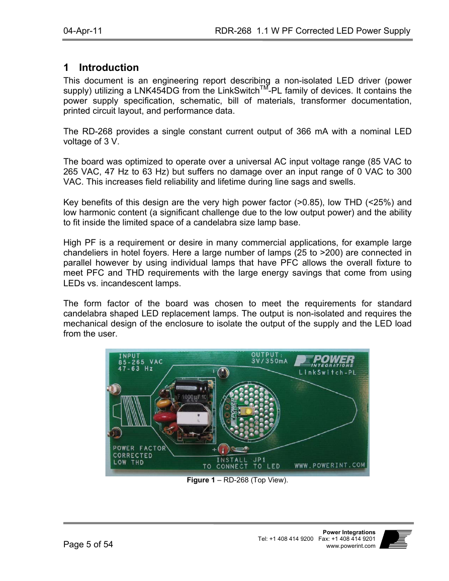
The form factor of the board was chosen to meet the requirements for standard
candelabra shaped LED replacement lamps. The output is non-isolated and requires the
mechanical design of the enclosure to isolate the output of the supply and the LED load
from the user.
Figure 1 – RD-268 (Top View).
Page 5 of 54
Power Integrations
Tel: +1 408 414 9200 Fax: +1 408 414 9201
www.powerint.com
�
RDR-268 1.1 W PF Corrected LED Power Supply
04-Apr-11
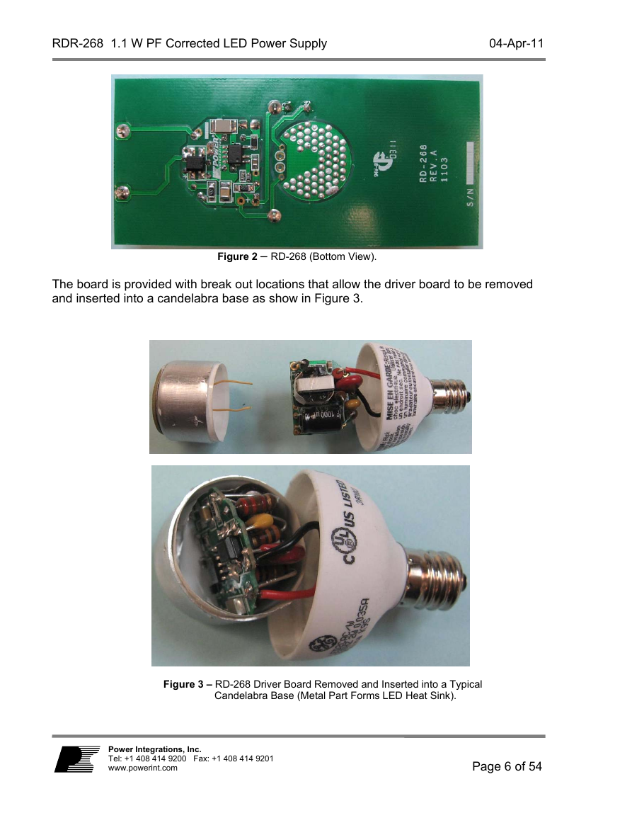
Figure 2 – RD-268 (Bottom View).
The board is provided with break out locations that allow the driver board to be removed
and inserted into a candelabra base as show in Figure 3.
Figure 3 – RD-268 Driver Board Removed and Inserted into a Typical
Candelabra Base (Metal Part Forms LED Heat Sink).
Power Integrations, Inc.
Tel: +1 408 414 9200 Fax: +1 408 414 9201
www.powerint.com
Page 6 of 54
�
04-Apr-11
RDR-268 1.1 W PF Corrected LED Power Supply
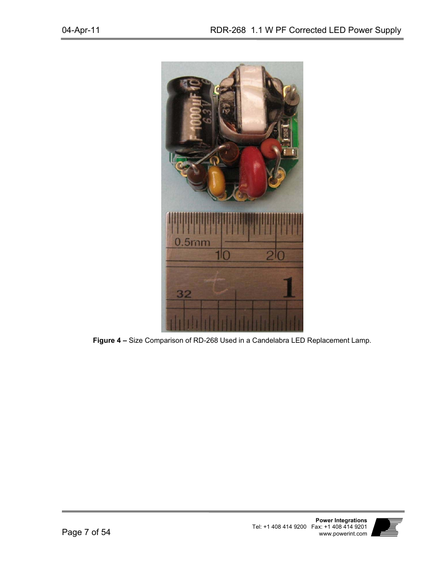
Figure 4 – Size Comparison of RD-268 Used in a Candelabra LED Replacement Lamp.
Page 7 of 54
Power Integrations
Tel: +1 408 414 9200 Fax: +1 408 414 9201
www.powerint.com
�
115/230
50/60
3
366
366
1.1
50
265
300
25
63
3.5
395
395
VAC
VAC
VAC
%
Hz
V
mA
mA
W
%
Meets CISPR22B / EN55015
Comment
Nominal line voltages
Normal operating range
Voltage range over which no damage to
the supply shall occur
Thermal results were verified with 3 V
LED string
(±8%) Nominal 115 VAC / 230 VAC
input, after reaching thermal equilibrium
(±10%) Extended 90 VAC-265 VAC
Input, -20 oC to 80 oC
Measured at POUT 25 oC
Mounted into candelabra metal finned
enclosure and measured on ground
plane (to simulate end application)
Input
Voltage
THD
Frequency
Output
Output Voltage
Output Current
Output Power
Efficiency
Environmental
Conducted EMI
Safety
Line Surge
Differential Mode
(L1-L2)
Ring Wave (100 kHz)
Differential Mode
(L1-L2)
Dimensions
Board Level Ambient
Temperature
VIN(NOM)
VIN(EXT)
VIN(ND)
ATHD
fLINE
VOUT
IOUT(N)
IOUT(E)
POUT
85
0
47
2.5
336
336
TAMB
-20
RDR-268 1.1 W PF Corrected LED Power Supply
04-Apr-11
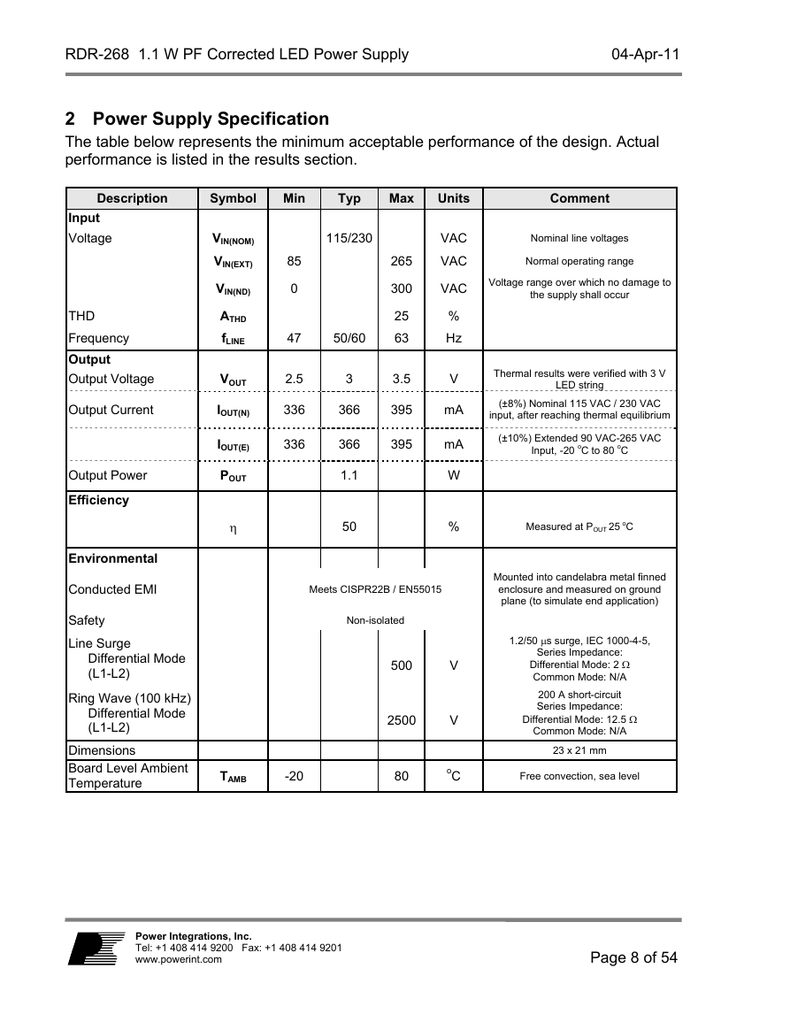
2 Power Supply Specification
The table below represents the minimum acceptable performance of the design. Actual
performance is listed in the results section.
Description
Symbol
Min
Typ
Max
Units
Non-isolated
500
2500
80
V
V
oC
1.2/50 s surge, IEC 1000-4-5,
Series Impedance:
Differential Mode: 2
Common Mode: N/A
200 A short-circuit
Series Impedance:
Differential Mode: 12.5
Common Mode: N/A
23 x 21 mm
Free convection, sea level
Power Integrations, Inc.
Tel: +1 408 414 9200 Fax: +1 408 414 9201
www.powerint.com
Page 8 of 54
�



 2023年江西萍乡中考道德与法治真题及答案.doc
 2012年重庆南川中考生物真题及答案.doc
 2013年江西师范大学地理学综合及文艺理论基础考研真题.doc
 2020年四川甘孜小升初语文真题及答案I卷.doc
 2020年注册岩土工程师专业基础考试真题及答案.doc
 2023-2024学年福建省厦门市九年级上学期数学月考试题及答案.doc
 2021-2022学年辽宁省沈阳市大东区九年级上学期语文期末试题及答案.doc
 2022-2023学年北京东城区初三第一学期物理期末试卷及答案.doc
 2018上半年江西教师资格初中地理学科知识与教学能力真题及答案.doc
 2012年河北国家公务员申论考试真题及答案-省级.doc
 2020-2021学年江苏省扬州市江都区邵樊片九年级上学期数学第一次质量检测试题及答案.doc
 2022下半年黑龙江教师资格证中学综合素质真题及答案.doc