Application
Note
EMW3280/EMW316x embedded Wi-Fi module
Update Firmware on EMW3280/EMW316x
3.0
Date:2013-05-30
Application Note
Embedded Wi-Fi module
Overview
EMW3280/EMW316x Wi-Fi modules are
designed for embedded applications. They have a
Cortex-M3 core MCU: STM32F2x5RG with rich
peripherals, 1M bytes flash and 128k bytes SRAM.
Users can build their own embedded Wi-Fi
applications based on mxchipWNetTM library
which manage all of the Wi-Fi MAC and TCP/IP
stack processing. We also provide several
mxchipWNetTM firmware to meet typical
applications: wireless UART, wireless audio,
wireless sensor etc.
This document describe the detailed steps to
change the firmware running on these modules.
Applications
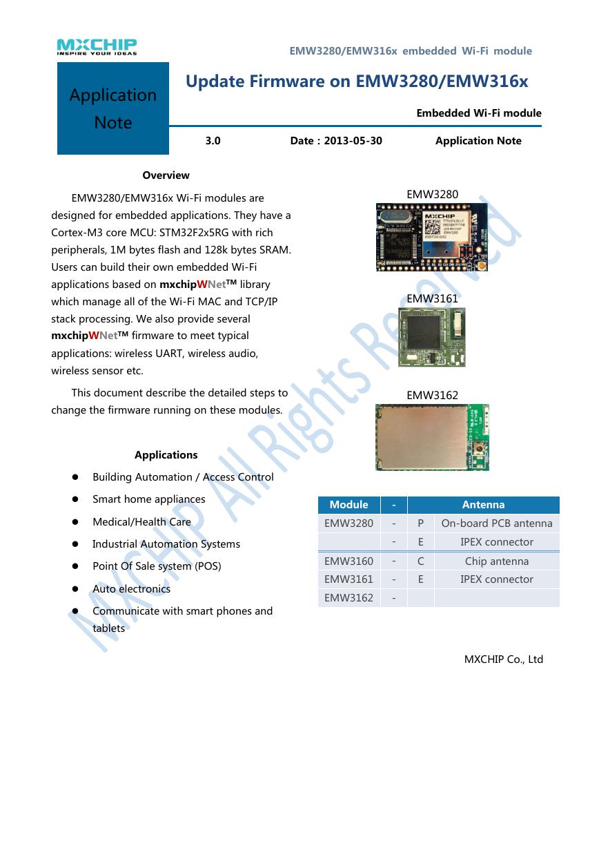
EMW3280
EMW3161
EMW3162
Building Automation / Access Control
Smart home appliances
Medical/Health Care
Industrial Automation Systems
Point Of Sale system (POS)
Auto electronics
Communicate with smart phones and
tablets
Module
EMW3280
EMW3160
EMW3161
EMW3162
-
-
-
-
-
-
Antenna
P On-board PCB antenna
E
C
E
IPEX connector
Chip antenna
IPEX connector
MXCHIP Co., Ltd
�
Contents
1
INTRODUCTION .................................................................................................. 3
2
UPDATE BY UART (SERIAL PORT) ..................................................................... 4
2.1 Hardware connection ................................................................................................................... 4
2.1.1
Ground the BOOT pin before power on ................................................................................................. 4
2.1.2
Connect the serial port ................................................................................................................................. 5
2.2
Send Firmware by Ymodem protocol ......................................................................................... 6
3
UPDATE BY A BUILD-IN WEB SERVER .............................................................. 8
4
SALES INFORMATION ........................................................................................ 9
5
TECHNICAL SUPPORT ........................................................................................ 9
2
�
1
Introduction
EMW3280/316x modules have Cortex-M3 MCU with rich peripherals, users can build
their own embedded Wi-Fi applications based on mxchipWNetTM library which manage
all of the Wi-Fi MAC and TCP/IP stack processing. MXCHIP also provide mxchipWNetTM
firmware to meet typical applications: wireless UART, wireless audio, wireless sensor etc.
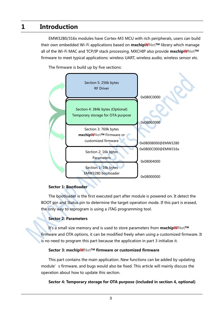
The firmware is build up by five sections:
Section 5: 256k bytes
RF Driver
Section 4: 384k bytes (Optional)
Temporary storage for OTA purpose
Section 3: 769k bytes
mxchipWNetTM Firmware or
customized firmware
Section 2: 16k bytes
Parameters
Section 1: 16k bytes
EMW3280 bootloader
0x080C0000
0x08060000
0x08008000@EMW3280
0x0800C000@EMW316x
0x08004000
0x08000000
Sector 1: Bootloader
The bootloader is the first executed part after module is powered on. It detect the
BOOT pin and Status pin to determine the target operation mode. If this part is erased,
the only way to reprogram is using a JTAG programming tool.
Sector 2: Parameters
It's a small size memory and is used to store parameters from mxchipWNetTM
firmware and OTA options, it can be modified freely when using a customized firmware. It
is no need to program this part because the application in part 3 initialize it.
Sector 3: mxchipWNetTM firmware or customized firmware
This part contains the main application. New functions can be added by updating
module’s firmware, and bugs would also be fixed. This article will mainly discuss the
operation about how to update this section.
Sector 4: Temporary storage for OTA purpose (included in section 4, optional)
3
�
It is a child area of the section 3. OTA data is temporarily stored here. When OTA is
performed, bootloader will use this part to replace other flash parts. Any data in this part
will be erased by bootloader if OTA operation is successful or no OTA function is pending.
If you want to use this part store our application, you should disable or modify the OTA
function in bootloader (section 1).
Sector 5: RF driver
This part contains RF driver and should not be modified in any circumstances.
Content of this section is released by MXCHIP as “driver.bin”. Reprogram this part with
this file if it is erased by accident.
2
Update by UART (Serial port)
Sector 1, 3, 5 can be reprogramed using a serial port if bootloader (Sector 1)
exists in the flash.
But it should be noted that
It is dangerous to reprogram the bootloader (Part 1), a failed operation may damage
the module. MXCHIP do not assume the losses caused by this operation.
EMW3280 has compatibility issue existed in the bootloader and the mxchipWNetTM
firmware in section 3. Firmware cannot work on the wrong bootloader. Table 1 shows
the detail.
Bootloader
mxchipWNetTM firmware
Compatible 1
EMW 3280Bootloader v4.x
020602xx, 02060301.xxx
Compatible 2
EMW 3280Bootloader v5.x
02060302.xxx, Custom firmware
Hardware connection
2.1.1 Ground the BOOT pin before power on
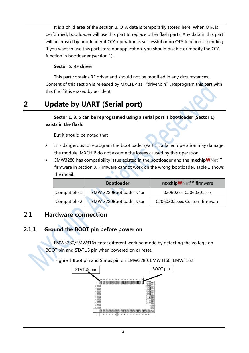
EMW3280/EMW316x enter different working mode by detecting the voltage on
BOOT pin and STATUS pin when powered on or reset.
Figure 1 Boot pin and Status pin on EMW3280, EMW3160, EMW3162
STATUS pin
BOOT pin
4
�
Figure 2 Boot pin and Status pin on EMW3161
No. 39: STATUS pin
No. 36: BOOT pin
Table 1 Working modes
BOOT
STATUS
0
0
1
0
1
X
Working mode
Test mode
Firmware update mode
Boot the application in Part 3
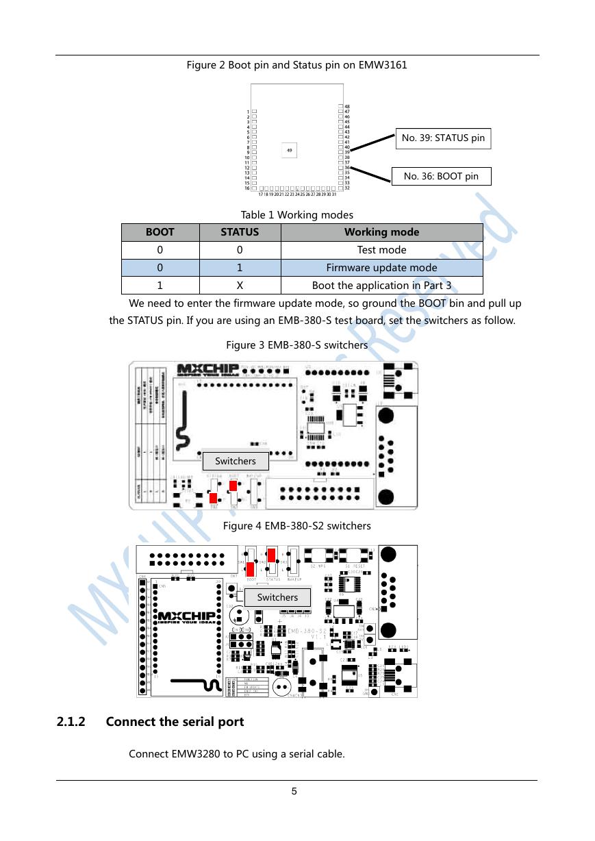
We need to enter the firmware update mode, so ground the BOOT bin and pull up
the STATUS pin. If you are using an EMB-380-S test board, set the switchers as follow.
Figure 3 EMB-380-S switchers
Switchers
Figure 4 EMB-380-S2 switchers
Switchers
2.1.2
Connect the serial port
Connect EMW3280 to PC using a serial cable.
5
�
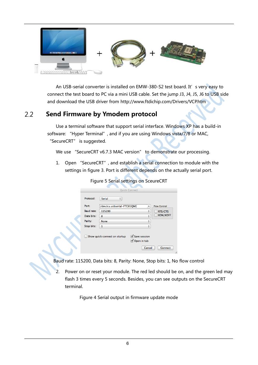
An USB-serial converter is installed on EMW-380-S2 test board. It’s very easy to
connect the test board to PC via a mini USB cable. Set the jump J3, J4, J5, J6 to USB side
and download the USB driver from http://www.ftdichip.com/Drivers/VCP.htm
Send Firmware by Ymodem protocol
Use a terminal software that support serial interface. Windows XP has a build-in
software: “Hyper Terminal”, and if you are using Windows vista/7/8 or MAC,
“SecureCRT” is suggested.
We use “SecureCRT v6.7.3 MAC version” to demonstrate our processing.
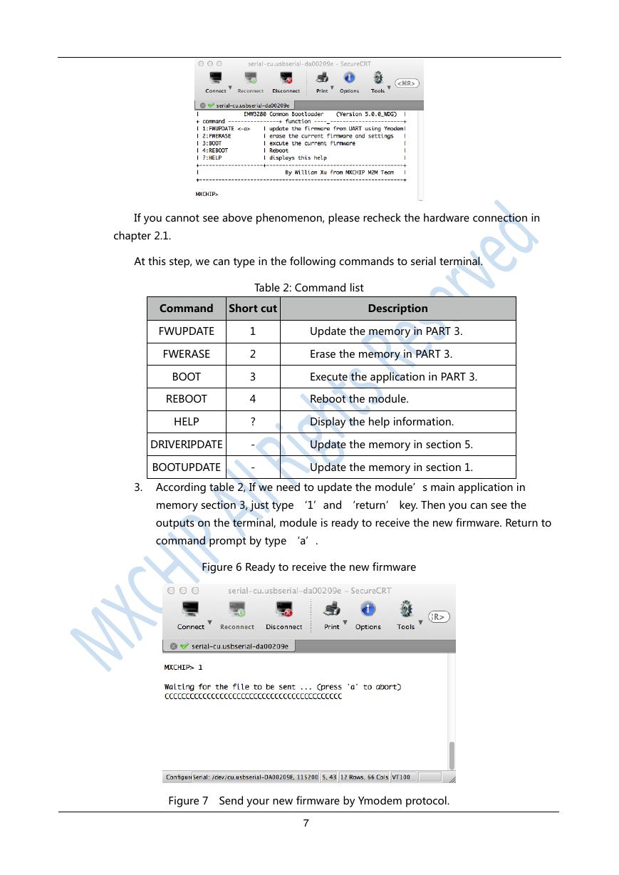
1. Open “SecureCRT”, and establish a serial connection to module with the
settings in figure 3. Port is different depends on the actually serial port.
Figure 5 Serial settings on SceureCRT
Baud rate: 115200, Data bits: 8, Parity: None, Stop bits: 1, No flow control
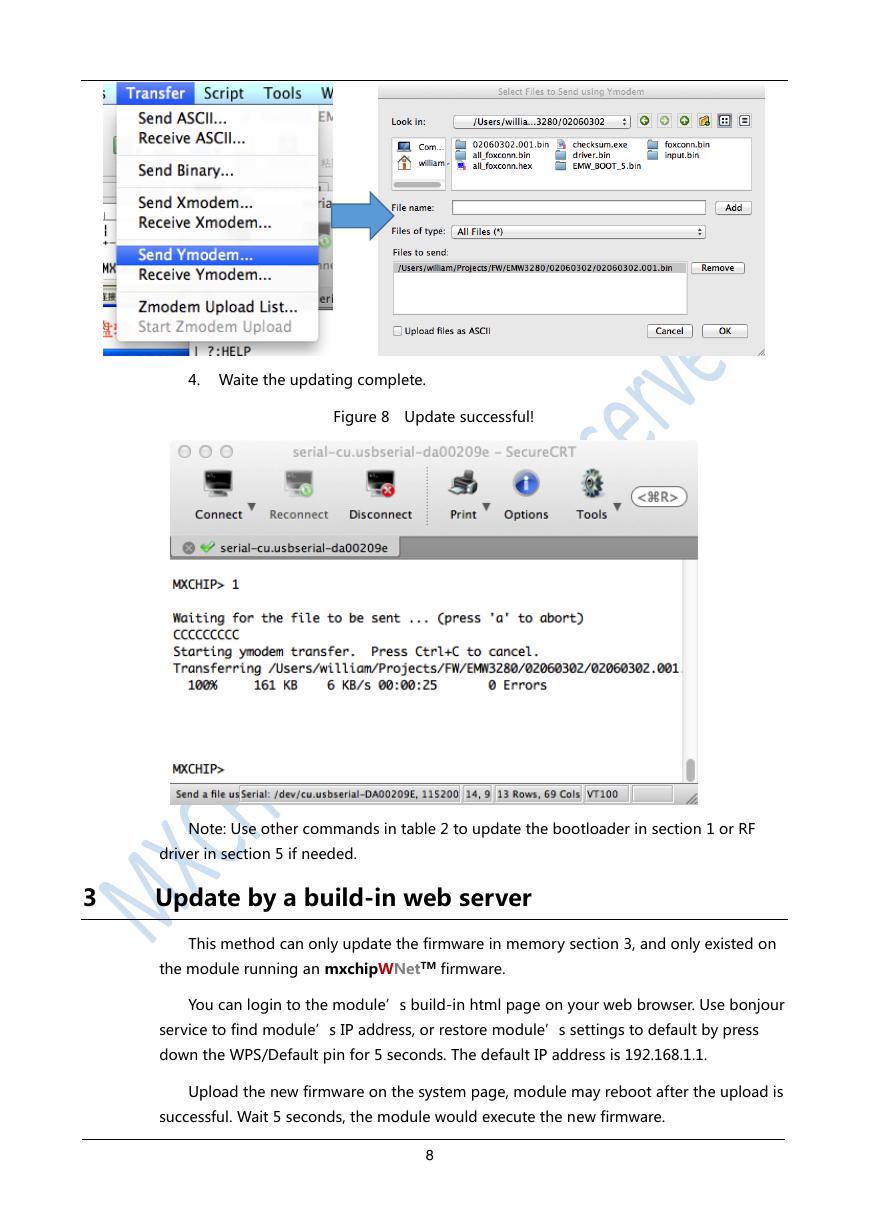
2. Power on or reset your module. The red led should be on, and the green led may
flash 3 times every 5 seconds. Besides, you can see outputs on the SecureCRT
terminal.
Figure 4 Serial output in firmware update mode
6
�
If you cannot see above phenomenon, please recheck the hardware connection in
chapter 2.1.
At this step, we can type in the following commands to serial terminal.
Table 2: Command list
Command Short cut
Description
FWUPDATE
FWERASE
BOOT
REBOOT
HELP
DRIVERIPDATE
BOOTUPDATE
1
2
3
4
?
-
-
Update the memory in PART 3.
Erase the memory in PART 3.
Execute the application in PART 3.
Reboot the module.
Display the help information.
Update the memory in section 5.
Update the memory in section 1.
3. According table 2, If we need to update the module’s main application in
memory section 3, just type ‘1’and ‘return’ key. Then you can see the
outputs on the terminal, module is ready to receive the new firmware. Return to
command prompt by type ‘a’.
Figure 6 Ready to receive the new firmware
Figure 7 Send your new firmware by Ymodem protocol.
7
�
4. Waite the updating complete.
Figure 8 Update successful!
Note: Use other commands in table 2 to update the bootloader in section 1 or RF
driver in section 5 if needed.
3
Update by a build-in web server
This method can only update the firmware in memory section 3, and only existed on
the module running an mxchipWNetTM firmware.
You can login to the module’s build-in html page on your web browser. Use bonjour
service to find module’s IP address, or restore module’s settings to default by press
down the WPS/Default pin for 5 seconds. The default IP address is 192.168.1.1.
Upload the new firmware on the system page, module may reboot after the upload is
successful. Wait 5 seconds, the module would execute the new firmware.
8
�



 V2版本原理图(Capacitive-Fingerprint-Reader-Schematic_V2).pdf
 摄像头工作原理.doc
 VL53L0X简要说明(En.FLVL53L00216).pdf
 原理图(DVK720-Schematic).pdf
 原理图(Pico-Clock-Green-Schdoc).pdf
 原理图(RS485-CAN-HAT-B-schematic).pdf
 File:SIM7500_SIM7600_SIM7800 Series_SSL_Application Note_V2.00.pdf
 ADS1263(Ads1262).pdf
 原理图(Open429Z-D-Schematic).pdf
 用户手册(Capacitive_Fingerprint_Reader_User_Manual_CN).pdf
 CY7C68013A(英文版)(CY7C68013A).pdf
 TechnicalReference_Dem.pdf