GPIF II Designer 1.0
Doc. No 001-75664 Rev. *C
Cypress Semiconductor
198 Champion Court
San Jose, CA 95134-1709
Phone (USA): 800.858.1810
Phone (Intnl): 408.943.2600
http://www.cypress.com
�
Copyrights
Copyrights
© Cypress Semiconductor Corporation, 2012-2013. The information contained herein is subject to change without notice.
Cypress Semiconductor Corporation assumes no responsibility for the use of any circuitry other than circuitry embodied in a
Cypress product. Nor does it convey or imply any license under patent or other rights. Cypress products are not warranted
nor intended to be used for medical, life support, life saving, critical control or safety applications, unless pursuant to an
express written agreement with Cypress. Furthermore, Cypress does not authorize its products for use as critical
components in life-support systems where a malfunction or failure may reasonably be expected to result in significant injury
to the user. The inclusion of Cypress products in life-support systems application implies that the manufacturer assumes all
risk of such use and in doing so indemnifies Cypress against all charges.
Trademarks
PSoC Designer™, Programmable System-on-Chip™, PSoC Creator™, and SmartSense™ are trademarks and PSoC® and
CapSense® are registered trademarks of Cypress Semiconductor Corp. All other trademarks or registered trademarks
referenced herein are property of the respective corporations.
Source Code
Any Source Code (software and/or firmware) is owned by Cypress Semiconductor Corporation (Cypress) and is protected
by and subject to worldwide patent protection (United States and foreign), United States copyright laws and international
treaty provisions. Cypress hereby grants to licensee a personal, non-exclusive, non-transferable license to copy, use,
modify, create derivative works of, and compile the Cypress Source Code and derivative works for the sole purpose of
creating custom software and or firmware in support of licensee product to be used only in conjunction with a Cypress
integrated circuit as specified in the applicable agreement. Any reproduction, modification, translation, compilation, or
representation of this Source Code except as specified above is prohibited without the express written permission of
Cypress.
Disclaimer
CYPRESS MAKES NO WARRANTY OF ANY KIND, EXPRESS OR IMPLIED, WITH REGARD TO THIS MATERIAL,
INCLUDING, BUT NOT LIMITED TO, THE IMPLIED WARRANTIES OF MERCHANTABILITY AND FITNESS FOR A
PARTICULAR PURPOSE. Cypress reserves the right to make changes without further notice to the materials described
herein. Cypress does not assume any liability arising out of the application or use of any product or circuit described herein.
Cypress does not authorize its products for use as critical components in life-support systems where a malfunction or failure
may reasonably be expected to result in significant injury to the user. The inclusion of Cypress‟ product in a life-support
systems application implies that the manufacturer assumes all risk of such use and in doing so indemnifies Cypress against
all charges.
Use may be limited by and subject to the applicable Cypress software license agreement.
2
Document No. 001-75664 Rev. *C
GPIF II Designer 1.0
�
Contents
GPIF II Designer 1.0 ............................................................................................................................................................... 1
Contents ................................................................................................................................................................................. 3
1.
Introduction .................................................................................................................................................................... 5
1.1 Welcome ............................................................................................................................................................... 5
1.2 About Help ............................................................................................................................................................. 5
1.3 Technical Support .................................................................................................................................................. 6
1.4 Document Revision History ................................................................................................................................... 6
2. Getting Started ............................................................................................................................................................... 7
2.1 Creating a GPIF II Project ..................................................................................................................................... 8
2.2 Designing a GPIF II Interface ................................................................................................................................ 9
2.3
Integrating GPIF II Configuration ........................................................................................................................... 9
2.4 Analyzing Signal Timings of the Interface ............................................................................................................ 10
3. Understanding GPIF II Designer ................................................................................................................................. 11
3.1 Concepts ............................................................................................................................................................. 11
3.1.1 Cypress Supplied Interfaces ................................................................................................................... 11
3.1.2
Interface Concepts.................................................................................................................................. 12
3.1.3 FX3 DMA Architecture ............................................................................................................................ 13
3.1.4 GPIF II State Machine Concepts ............................................................................................................ 14
3.1.5 Timing Simulation Concepts ................................................................................................................... 14
3.2 User Interface ...................................................................................................................................................... 15
3.2.1 Start Page ............................................................................................................................................... 15
Interface Definition .................................................................................................................................. 15
3.2.2
3.2.3
Interface Customization .......................................................................................................................... 18
3.2.4 State Machine Canvas ............................................................................................................................ 18
3.2.5 Timing ..................................................................................................................................................... 20
3.2.6 Output Window and Notice List Window ................................................................................................. 22
3.2.7 Documentation and Context Help ........................................................................................................... 22
3.3 Tabs, Menus, and Shortcuts ................................................................................................................................ 23
3.3.1 Application Toolbar ................................................................................................................................. 23
3.3.2 File Menu ................................................................................................................................................ 23
3.3.3 View Menu .............................................................................................................................................. 24
3.3.4 Build Menu .............................................................................................................................................. 24
3.3.5 Timing Simulation ................................................................................................................................... 24
GPIF II Designer 1.0
Document No. 001-75664 Rev. *C
3
�
Contents
3.3.6 Help Menu .............................................................................................................................................. 24
3.3.7 Shortcut Keys ......................................................................................................................................... 25
4. Programming GPIF II State Machine .......................................................................................................................... 26
4.1 GPIF II Overview ................................................................................................................................................. 26
4.2 GPIF II State Machine ......................................................................................................................................... 27
4.3 GPIF II Actions .................................................................................................................................................... 27
4.3.1 Action - IN_ADDR ................................................................................................................................... 32
4.3.2 Action - IN_DATA ................................................................................................................................... 32
4.3.3 Action - DR_DATA .................................................................................................................................. 33
4.3.4 Action - DR_ADDR ................................................................................................................................. 34
4.3.5 Action - COMMIT .................................................................................................................................... 34
4.3.6 Action - DR_GPIO .................................................................................................................................. 35
4.3.7 Action - LD_ADDR_COUNT ................................................................................................................... 36
4.3.8 Action - LD_DATA_COUNT .................................................................................................................... 37
4.3.9 Action - LD_CTRL_COUNT .................................................................................................................... 38
4.3.10 Action - COUNT_ADDR .......................................................................................................................... 38
4.3.11 Action - COUNT_DATA .......................................................................................................................... 38
4.3.12 Action - COUNT_CTRL .......................................................................................................................... 38
4.3.13 Action - CMP_ADDR .............................................................................................................................. 38
4.3.14 Action - CMP_DATA ............................................................................................................................... 39
4.3.15 Action - CMP_CTRL ............................................................................................................................... 40
4.3.16 Action - INTR_CPU ................................................................................................................................. 40
4.3.17 Action - INTR_HOST .............................................................................................................................. 40
4.3.18 Action - DR_DRQ ................................................................................................................................... 41
4.4 GPIF II Transition Equations and Triggers .......................................................................................................... 42
4.5 GPIF II Constraints .............................................................................................................................................. 43
4.5.1 Mirror States ........................................................................................................................................... 43
4.5.2
Intermediate States ................................................................................................................................. 47
4.6 Designing a GPIF II State Machine ..................................................................................................................... 47
4.6.1
Illustration of Implementing Asynchronous SRAM Interface ................................................................... 48
4.6.2 Analyzing Timing .................................................................................................................................... 56
4.7 GPIF II firmware API ............................................................................................................................................ 57
4
Document No. 001-75664 Rev. *C
GPIF II Designer 1.0
�
1. Introduction
1.1 Welcome
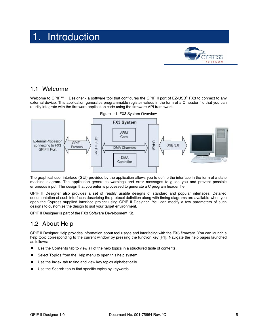
Welcome to GPIF™ II Designer - a software tool that configures the GPIF II port of EZ-USB® FX3 to connect to any
external device. This application generates programmable register values in the form of a C header file that you can
readily integrate with the firmware application code using the firmware API framework.
Figure 1-1. FX3 System Overview
The graphical user interface (GUI) provided by the application allows you to define the interface in the form of a state
machine diagram. The application generates warnings and error messages to guide you and prevent possible
erroneous input. The design that you enter is processed to generate a C program header file.
GPIF II Designer also provides a set of readily usable designs of standard and popular interfaces. Detailed
documentation of such interfaces describing the protocol definition along with timing diagrams are available when you
open the Cypress supplied interface project using GPIF II Designer. You can modify a few parameters of such
designs to customize the design to suit your target environment.
GPIF II Designer is part of the FX3 Software Development Kit.
1.2 About Help
GPIF II Designer Help provides information about tool usage and interfacing with the FX3 firmware. You can launch a
help topic corresponding to the current window by pressing the function key [F1]. Navigate the help pages launched
as follows:
Use the Contents tab to view all of the help topics in a structured table of contents.
Select Topics from the Help menu to open this help system.
Use the Index tab to find and view key topics alphabetically.
Use the Search tab to find specific topics by keywords.
GPIF II Designer 1.0
Document No. 001-75664 Rev. *C
5
�
Introduction
1.3 Technical Support
If you have any technical questions or issues related to GPIF II Designer, you can contact Cypress by sending an
email to usb3@cypress.com.
More information about EZ-USB FX3 is available at www.cypress.com/go/superspeed.
You can also call Cypress Customer Support by dialing:
+1 (800) 541-4736 Ext. 8 (in the USA)
+1 (408) 943-2600 Ext. 8 (International)
Or visit www.cypress.com/go/support.
1.4 Document Revision History
Revision
Issue Date
Origin of Change
Description of Change
**
*A
*B
*C
01/17/2012
02/29/2012
VTV
VTV
09/13/2012
03/20/2013
MRAO
MRAO
New document.
Updated the user manual with comments from Beta
customers and Applications and Design. The change also
includes update of text and figures to reflect changes
made after the beta release.
Updated all the figures across the document.
Updated the descriptions of the state machine actions.
6
Document No. 001-75664 Rev. *C
GPIF II Designer 1.0
�
2. Getting Started
One of the key features of EZ-USB FX3 is the flexibility and programmability of the general programmable interface
(GPIF II). GPIF II is a programmable state machine that allows you to configure FX3 to connect to any processor
interface. The GPIF II state machine is defined by a set of programmable memory mapped registers. These registers
are configured by the firmware application running on the EZ-USB FX3. The register configuration that programs
GPIF II for a specific interface can be generated by the software tool GPIF II Designer.
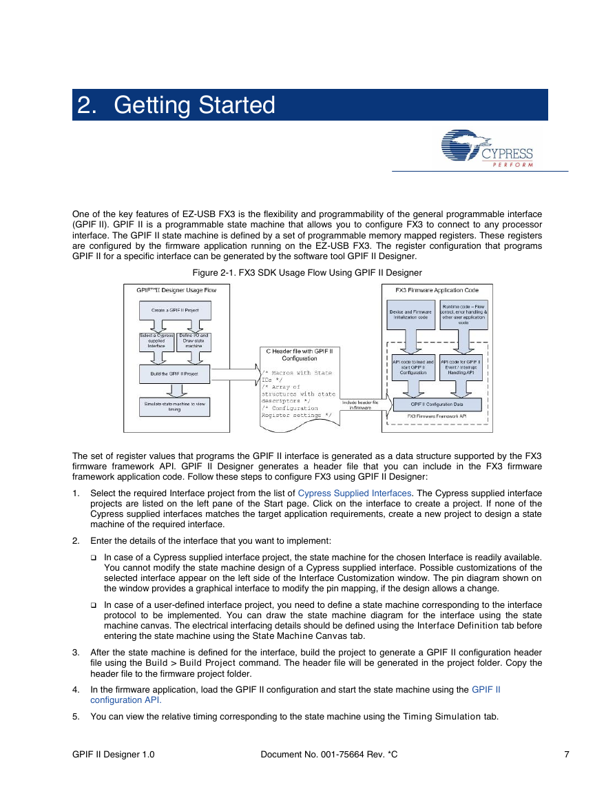
Figure 2-1. FX3 SDK Usage Flow Using GPIF II Designer
The set of register values that programs the GPIF II interface is generated as a data structure supported by the FX3
firmware framework API. GPIF II Designer generates a header file that you can include in the FX3 firmware
framework application code. Follow these steps to configure FX3 using GPIF II Designer:
1. Select the required Interface project from the list of Cypress Supplied Interfaces. The Cypress supplied interface
projects are listed on the left pane of the Start page. Click on the interface to create a project. If none of the
Cypress supplied interfaces matches the target application requirements, create a new project to design a state
machine of the required interface.
2. Enter the details of the interface that you want to implement:
In case of a Cypress supplied interface project, the state machine for the chosen Interface is readily available.
You cannot modify the state machine design of a Cypress supplied interface. Possible customizations of the
selected interface appear on the left side of the Interface Customization window. The pin diagram shown on
the window provides a graphical interface to modify the pin mapping, if the design allows a change.
In case of a user-defined interface project, you need to define a state machine corresponding to the interface
protocol to be implemented. You can draw the state machine diagram for the interface using the state
machine canvas. The electrical interfacing details should be defined using the Interface Definition tab before
entering the state machine using the State Machine Canvas tab.
3. After the state machine is defined for the interface, build the project to generate a GPIF II configuration header
file using the Build > Build Project command. The header file will be generated in the project folder. Copy the
header file to the firmware project folder.
4.
In the firmware application, load the GPIF II configuration and start the state machine using the GPIF II
configuration API.
5. You can view the relative timing corresponding to the state machine using the Timing Simulation tab.
GPIF II Designer 1.0
Document No. 001-75664 Rev. *C
7
�
Getting Started
2.1 Creating a GPIF II Project
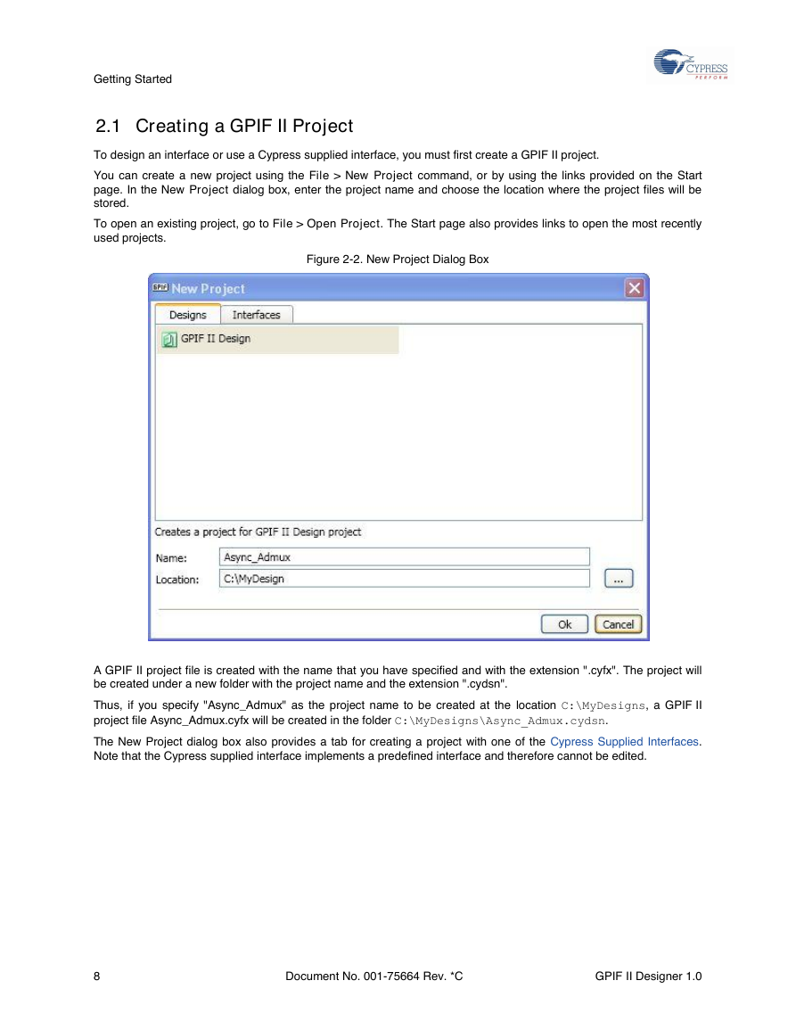
To design an interface or use a Cypress supplied interface, you must first create a GPIF II project.
You can create a new project using the File > New Project command, or by using the links provided on the Start
page. In the New Project dialog box, enter the project name and choose the location where the project files will be
stored.
To open an existing project, go to File > Open Project. The Start page also provides links to open the most recently
used projects.
Figure 2-2. New Project Dialog Box
A GPIF II project file is created with the name that you have specified and with the extension ".cyfx". The project will
be created under a new folder with the project name and the extension ".cydsn".
Thus, if you specify "Async_Admux" as the project name to be created at the location C:\MyDesigns, a GPIF II
project file Async_Admux.cyfx will be created in the folder C:\MyDesigns\Async_Admux.cydsn.
The New Project dialog box also provides a tab for creating a project with one of the Cypress Supplied Interfaces.
Note that the Cypress supplied interface implements a predefined interface and therefore cannot be edited.
8
Document No. 001-75664 Rev. *C
GPIF II Designer 1.0
�


 2023年江西萍乡中考道德与法治真题及答案.doc
 2012年重庆南川中考生物真题及答案.doc
 2013年江西师范大学地理学综合及文艺理论基础考研真题.doc
 2020年四川甘孜小升初语文真题及答案I卷.doc
 2020年注册岩土工程师专业基础考试真题及答案.doc
 2023-2024学年福建省厦门市九年级上学期数学月考试题及答案.doc
 2021-2022学年辽宁省沈阳市大东区九年级上学期语文期末试题及答案.doc
 2022-2023学年北京东城区初三第一学期物理期末试卷及答案.doc
 2018上半年江西教师资格初中地理学科知识与教学能力真题及答案.doc
 2012年河北国家公务员申论考试真题及答案-省级.doc
 2020-2021学年江苏省扬州市江都区邵樊片九年级上学期数学第一次质量检测试题及答案.doc
 2022下半年黑龙江教师资格证中学综合素质真题及答案.doc