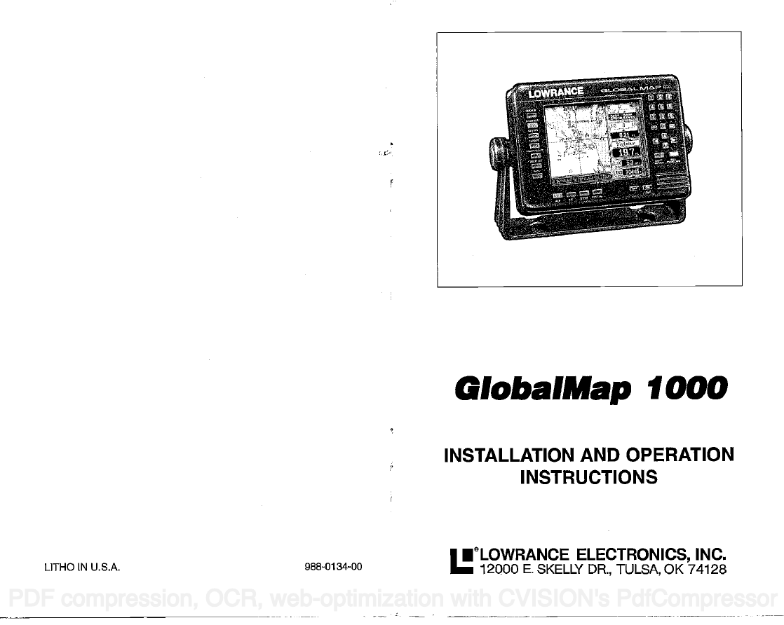
GlobalMap 1000
INSTALLATION AND OPERATION
INSTRUCTIONS
LITHO IN U.S.A.
988-0134-00
•eL0wRANcE ELECTRONICS, INC.
12000 E. SKELLY DR., TULSA, OK 74128
PDF compression, OCR, web-optimization with CVISION's PdfCompressor
�
NOTES:
WARNING!
USE THIS MAPPING UNIT ONLY AS AN AID TO NAVIGATION. A
CAREFUL NAVIGATOR NEVER RELIES ON ONLY ONE METHOD TO
OBTAIN POSITION INFORMATION.
The background maps built into this unit are not intended for navigation.
The accuracy of these maps has not been verified. The maps are derived
from U.S. Government sources which rely on ground and aerial surveys
and satellite data. Since there can be inaccuracies in the data used to
create the map and the maps resolution, and position inaccuracies in the
navigation system, you should use caution when using this product.
CAUTION
When showing navigation data to a position (waypoint), this unit will show
the shortest, most direct path to the waypoint regardless of obstacles.
Therefore, the prudent navigator will not only take advantage of all
available navigation tools when travelling to a waypoint, but will also
visually check to make certain a clear, safe path to the waypoint is always
available.
NOTICE!
As of this writing, the Department of Defense (DOD) has not declared the
GPS navigation system operational. The system is still in a testing phase.
Satellites can be turned off or accuracy can be degraded at will by the
system operators. Remember this if you use a GPS receiver as the
position input to the GlobalMap 1000.
C-MAFI
The CMAPTM database is not intended as a replacement of official
nautical charts which are required for safe navigation.
CMAPTM
Copyright® 1993 Lowrance Electronics, Inc.
All rights reserved.
All features and specifications subject to change without notice.
All screens in this manual are simulated.
PDF compression, OCR, web-optimization with CVISION's PdfCompressor
�
NOTES:
TABLE OF CONTENTS
INTRODUCTION
MOUNTING
BRACKET MOUNT
IN-DASH MOUNT
POWER CONNECTIONS
DATA INPUT AND OUTPUT CONNECTIONS
DGPS BEACON RECEIVER
MAPLINKIM
LOWRANCE GPS MODULE INSTALLATION
KEYBOARD
GE1TING STARTED INITIALIZATION
DGPSSETUP
LOWRANCELGC-1 GPS MODULE
COLD START
LGC-1 GPS MODULE TEST
MAPPING/NAVIGATION/STEERING DISPLAYS
MAP SCREEN
MAPPING OPTIONS
CARTRIDGE SWITCH
C-MAP SETUP
CURSOR
TRAIL PLOTTER
EVENT MARKER
NAVIGATION SCREEN
STEERING SCREEN
CDI. RANGE
HOW TO SAVE A WAYPOINT
QUICK SAVE METHOD
VIEW AND SAVE METHOD
EDITING A WAYPOINT
WAYPOINT SYMBOLS
GOTOAWAYPOINT
CANCEL NAVIGATION
ERASE A WAYPOINT
WAYPOINT DISPLAY
ROUTES
CREATING A ROUTE
NAMEA ROUTE
WAYPOINT SELECTION
REMOVEAWAYPOINT
EDIT WAYPOINT
ERASEAROUTE
FOLLOWING A ROUTE
GPS ALARMS
SATELLITEJDGPS INFORMATION SCREEN
CUSTOMIZE SCREENS
WAYPOINT NAVIGATION
ARRIVAL ALARM
XTE (CROSS TRACK ERROR) ALARM
ANCHOR ALARM
PERPENDICULAR ALARM
NMEA OUTPUT
UNITS OF MEASURE
CONTRAST, VOLUME, AND LIGHT ADJUSTMENT
MAN OVERBOARD
DATIJMS
PCF (Position Correcllon Factor)
POSITION FILTER
PRESET
GPS SIMULATOR
LAST-MINUTE CHANGES
2
3
4
7
10
II
14
15
16
17
19
19
20
21
23
25
25
26
27
29
31
32
33
33
35
37
37
37
37
38
39
40
40
41
41
42
42
42
43
46
46
46
47
49
49
50
50
SI
SI
52
53
53
55
56
58
58
58
59
PDF compression, OCR, web-optimization with CVISION's PdfCompressor
�
NOTES:
PDF compression, OCR, web-optimization with CVISION's PdfCompressor
�
6. TRAIL PLOT
If you turn the plot trail recording off, (using the Trail Recording function
on the "Mapping Setup" menu) then the GlobalMap 1000 will stop
plotting your trail. However, it will show your trail on the map up to the
point that you turned it off.
7. TRAIL PLOT
There is a maximum of 2000 dots available to plot a trail.
8. EVENT MARKER
Pressing the EVENT MARKER key twice puts the last used marker at
your present position or at the cursor position if it's displayed.
9. EVENT MARKER
You can't erase event markersfrom the displaywhen it's in the "course-
up" mode.
10.The storage temperature for your unit is from -4 degrees to +167
degrees Fahrenheit (-20 to ÷75 degrees Celcius). Extended storage
temperatures higher or lowerthan specified will cause the liquid crystal
display to fail. Neither this type of failure nor its consequences are
covered by the warranty. For more information, consult the factory
customer service department.
INTRODUCTION
The GlobalMap 1000 is a high quality, wide screen mapping unit with
performance that is second to none in its class. Using menu features and
"soft-key" operation, the GlobalMap 1000 is also one of the easiest-to-use
products that Lowrance has ever built. It sets new standards in mapping
versatility and performance by combining a built-in reference map (back-
ground map) with the ability to read mapping cartridges (requires optional
MapLinkTM cartridge reader.) The displayand keyboard are also lighted for
night operation.
The GlobalMap 1000's built-in background map includes virtually the
whole world, however, over7o% of the map's detail is in the 48-contiguous
states, HawaD, and southern Canada. If you install the MapLink cartridge
reader, the GlobalMap 1000 can display highly detailed charts available on
C-Map cartridges, covering most coastal areas around the world. In the
future, Lowrancewill also have cartridges availablethatcover many inland
areas.
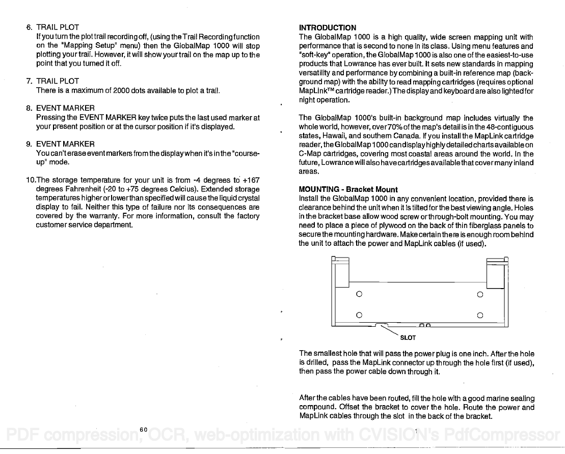
MOUNTING - Bracket Mount
Install the GlobalMap 1000 in any convenient location, provided there is
clearance behind the unit when it is tilted forthe best viewing angle. Holes
in the bracket base allow wood screw or through-bolt mounting. You may
need to place a piece of plywood on the back of thin fiberglass panels to
secure the mounting hardware. Make certain there is enough room behind
the unit to attach the power and MapLink cables (if used).
SLOT
The smallest hole that will pass the power plug is one inch. After the hole
is drilled, pass the MapLink connector up through the hole first (if used),
then pass the power cable down through it.
After the cables have been routed, fill the hole with a good marine sealing
compound. Offset the bracket to cover the hole. Route the power and
MapLink cables through the slot in the back of the bracket.
PDF compression, OCR, web-optimization with CVISION's PdfCompressor
60
�
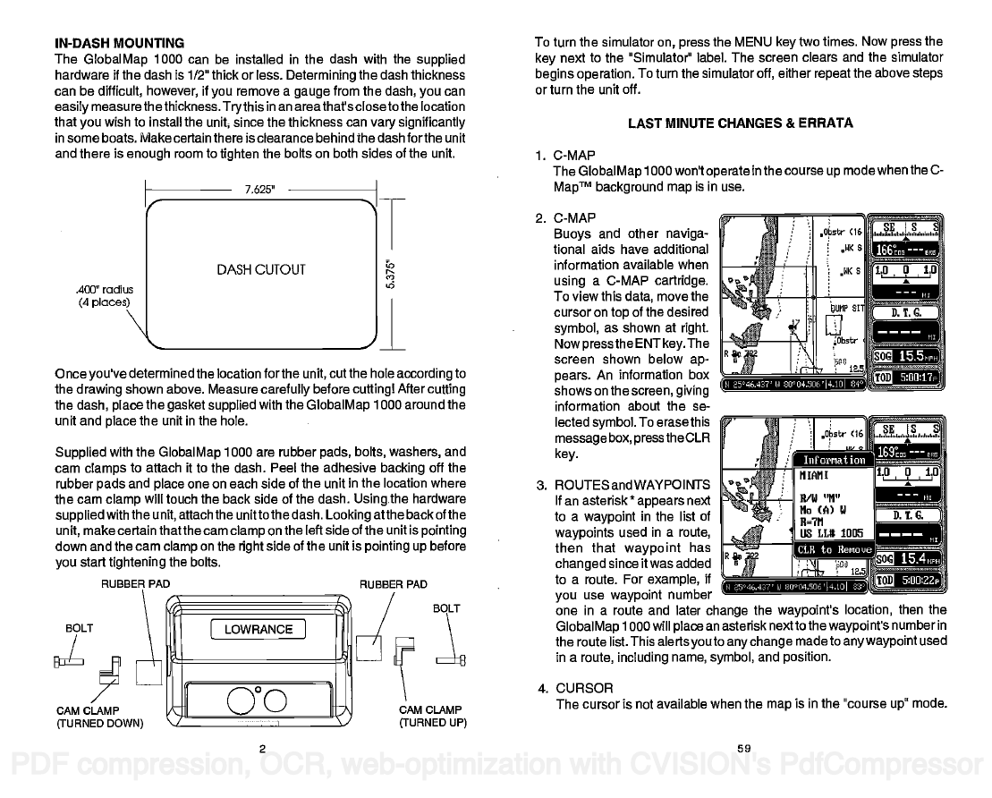
IN-DASH MOUNTING
The GlobalMap 1000 can be installed in the dash with the supplied
hardware if the dash is 1/2" thick or less. Determining the dash thickness
can be difficult, however, if you remove a gauge from the dash, you can
easily measure thethickness. Trythis in an areathat's closeto the location
that you wish to install the unit since the thickness can vary significantly
in some boats. Make certain there is clearance behind the dash forthe unit
and there is enough room to tighten the bolts on both sides of the unit.
7,625'
DASH CUTOUT
"
T
'a
.400" radius
(4 places)
'—
Once you've determined the location forthe unit, cut the hole according to
the drawing shown above. Measure carefully before cuttingl After cutting
the dash, place the gasket supplied with the GlobalMap 1000 around the
unit and place the unit in the hole.
Supplied with the GlobalMap 1000 are rubber pads, bolts, washers, and
cam clamps to attach it to the dash. Peel the adhesive backing off the
rubber pads and place one on each side of the unit in the location where
the cam clamp will touch the back side of the dash. Usingthe hardware
supplied with the unit, attach the unitto the dash. Looking atthe back of the
unit, make certain that the cam clamp on the left side of the unit is pointing
down and the cam clamp on the right side of the unit is pointing up before
you start tightening the bolts.
RUBBER PAD
RUBBER PAD
BOLT
BOLT
[ LOWRANCJ
To turn the simulator on, press the MENU key two times. Now press the
key next to the "Simulator" label. The screen clears and the simulator
begins operation. To turn the simulator off, either repeat the above steps
or turn the unit off.
LAST MINUTE CHANGES & ERRATA
1. C-MAP
The GlobalMap 1000 won't operate in the course up mode when the C-
MapTM background map is in use.
2. C-MAP
Buoys and other naviga-
tional aids have additional
information available when
using a C-MAP cartridge.
To view this data, move the
cursor on top of the desired
symbol, as shown at right.
Now pressthe ENT key. The
screen shown below ap-
pears. An information box
shows on the screen, giving
information about the se-
lected symbol. To erasethis
message box, press the CLR
key.
15.5
H 25°46.42?' LI 8OU4.UE'l4.1O
Iiuforriat ion
3. ROUTES and WAYPOINTS
If an asterisk *
appears next
to a waypoint in the list of
waypoints used in a route,
then that waypoint has
changed since it was added
to a route. For example, if
you use waypoint number
one in a route and later change the waypoint's location, then the
GlobalMap 1000 will place an asterisk next to the waypoint's number in
the route list. This alerts you to any change made to any waypoint used
in a route, including name, symbol, and position.
CLR to Benouc
5:Ofl22p
CAM CLAMP
(TURNED DOWN)
GO
1
CAM CLAMP
(TURNED UP)
4. CURSOR
The cursor is not available when the map is in the "course up" mode.
PDF compression, OCR, web-optimization with CVISION's PdfCompressor
2
59
�
Customtize Display a-
— a
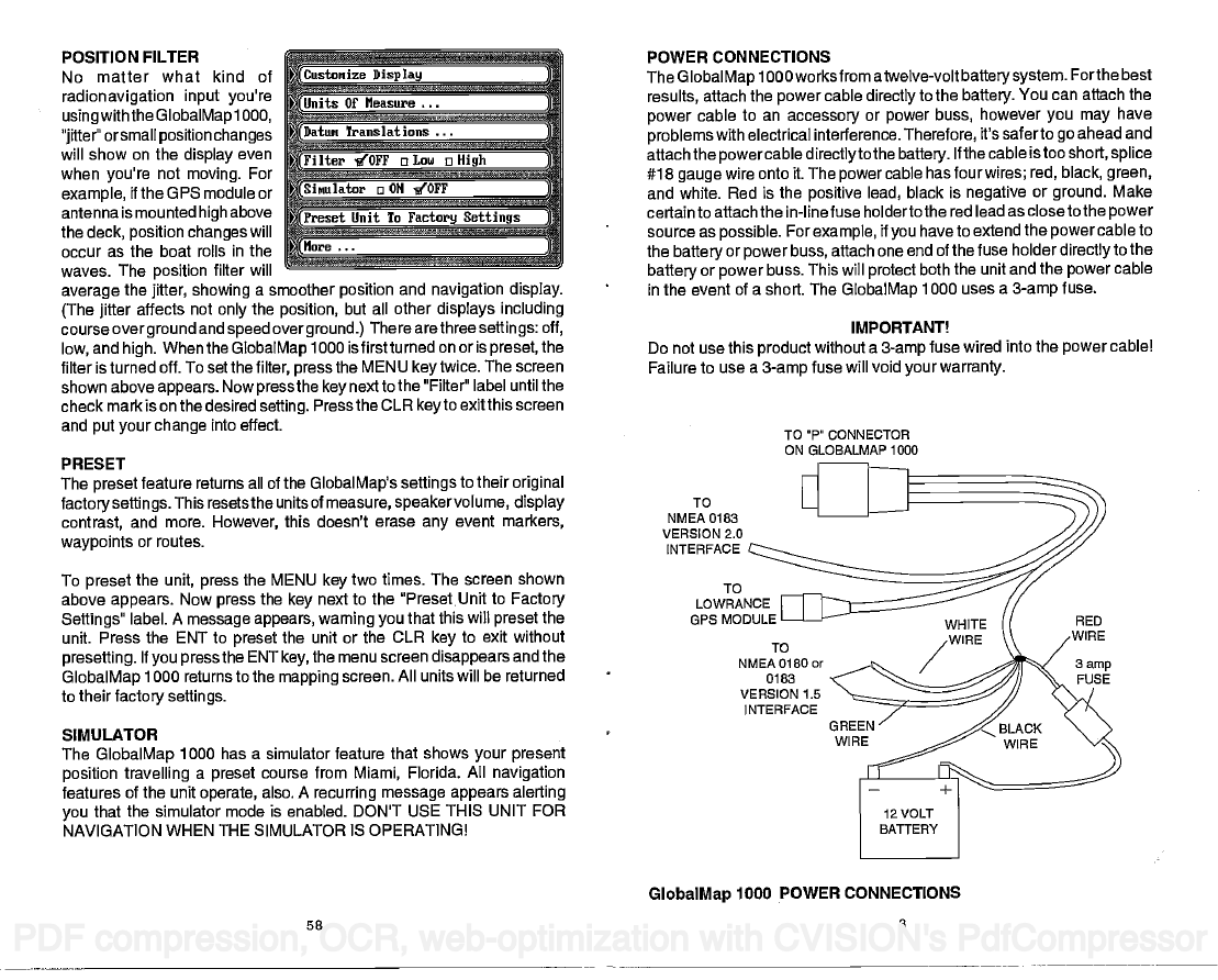
POSITION FILTER
No matter what kind of
__________________
radionavigation input you're
Units Of fleasure
using with the GlobalMap 1000,
___________________
)attut Translations
"jitter" orsmall position changes
______________
will show on the display even
Filter 10FF OLOW a High
when you're not moving. For
______________________________
example, the GPS module or
Sinulator a ON 10FF
_____ ____
antenna is mounted high above
Preset Unit To Factory Settings
the deck, position changes will
______________________________
More
occur as the boat rolls in the
____________________________
waves. The position filter will
average the jitter, showing a smoother position and navigation display.
(The jitter affects not only the position, but all other displays including
course over ground and speed over ground.) There arethree settings: off,
low, and high. When the GlobalMap 1000 is firstturned on or is preset, the
filter is turned off. To set the filter, press the MENU key twice. The screen
shown above appears. Now press the key next to the "Filter" label until the
check mark is on the desired setting. Press the CLR key to exit this screen
and put your change into effect.
______
PRESET
The preset feature returns all of the GlobalMap's settings to their original
factorysettings. This resetsthe units of measure, speakervolume, display
contrast, and more. However, this doesn't erase any event markers,
waypoints or routes.
To preset the unit, press the MENU key two times. The screen shown
above appears. Now press the key next to the °PresetUnit to Factory
Settings" label. A message appears, warning you that this will preset the
unit. Press the ENT to preset the unit or the CLR key to exit without
presetting. If you press the ENT key, the menu screen disappears and the
GlobalMap 1000 returns to the mapping screen. All units will be returned
to their factory settings.
SIMULATOR
The GlobalMap 1000 has a simulator feature that shows your present
position travelling a preset course from Miami, Florida. All navigation
features of the unit operate, also. A recurring message appears alerting
you that the simulator mode is enabled. DON'T USE THIS UNIT FOR
NAVIGATION WHEN THE SIMULATOR IS OPERATING!
POWER CONNECTIONS
The GlobalMap 1000 worksfrom atwelve-volt batterysystem. Forthe best
results, attach the power cable directly to the battery. You can attach the
power cable to an accessory or power buss, however you may have
problems with electrical interference. Therefore, it's saferto go ahead and
attach the powercable directlyto the battery. If the cable istoo short, splice
#18 gauge wire onto it. The power cable has four wires; red, black, green,
and white. Red is the positive lead, black is negative or ground. Make
certain to attach the in-line fuse holderto the red lead as closeto the power
source as possible. For example, if you have to extend the power cable to
the battery or power buss, attach one end of the fuse holder directly to the
battery or power buss. This will protect both the unit and the power cable
in the event of a short. The GlobalMap 1000 uses a 3-amp fuse.
Do not use this product without a 3-amp fuse wired into the power cable!
Failure to use a 3-amp fuse will void your warranty.
IMPORTANT!
TO P' CONNECTOR
ON GLOBALMAP 1000
TO
NMEA 0183
VERSION 2.0
INTERFACE
TO
LOW RAN c F
GPS MODULE
NMEA 0180 or
TO
0183
VERSION 1.5
INTER FACE
GlobalMap 1000 POWER CONNECTIONS
PDF compression, OCR, web-optimization with CVISION's PdfCompressor
3
58
�
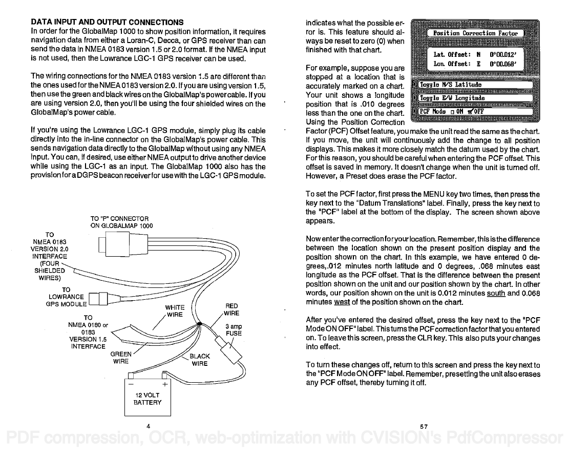
DATA INPUT AND OUTPUT CONNECTIONS
In order for the GlobalMap 1000 to show position information, it requires
navigation data from either a Loran-C, Decca, or GPS receiver than can
send the data in NMEA 0183 version 1.5 or 2.0 format. If the NMEA input
is not used, then the Lowrance LGC-1 GPS receiver can be used.
The wiring connections for the NMEA 0183 version 1.5 are different than
the ones used forthe NMEA 0183 version 2.0. If you are using version 1.5,
then use the green and black wires on the GlobalMap's powercable. If you
are using version 2.0, then you'll be using the four shielded wires on the
GlobalMap's power cable.
If you're using the Lowrance LGC-1 GPS module, simply plug its cable
directly into the in-line connector on the GlobalMap's power cable. This
sends navigation data directly to the GlobalMap without using any NMEA
input. You can, if desired, use either NMEA output to drive another device
while using the LGC-1 as an input. The GlobalMap 1000 also has the
provision fora DGPS beacon receiverforuse with the LGC-1 GPS module.
TO"P"OONNECTOR
ON GLOBALMAP 1000
TO
NMEA 0183
VERSION 2.0
INTER FACE
(FOUR
SHIELDED
WIRES)
LOWRANCE
OPS MODULE
To
NMEA 0180 or
0183
VERSION 1.5
INTERFACE
indicates what the possible er-
ror is. This feature should al-
ways be reset to zero (0) when
finished with that chart.
For example, suppose you are
stopped at a location that is
accurately marked on a chart.
Your unit shows a longitude
position that is .010 degrees
less than the one on the chart.
Using the Position Correction
Factor (PCF) Offset feature, you makethe unit read the same as the chart.
If you move, the unit will continuously add the change to all position
displays. This makes it more closely match the datum used by the chart.
For this reason, you should be careful when entering the PCF offset. This
offset is saved in memory. It doesn't change when the unit is turned off.
However, a Preset does erase the PCF factor.
To set the PCF factor, first press the MENU key two times, then press the
key next to the "Datum Translations label. Finally, press the key next to
the "PCF" label at the bottom of the display. The screen shown above
appears.
Nowenterthe correction foryour location. Remember, this isthe difference
between the location shown on the present position display and the
position shown on the chart. In this example, we have entered 0 de-
grees,.012 minutes north latitude and 0 degrees, .068 minutes east
longitude as the PCF offset. That is the difference between the present
position shown on the unit and our position shown by the chart. In other
words, our position shown on the unit is 0.012 minutes south and 0.068
minutes wt of the position shown on the chart.
After you've entered the desired offset, press the key next to the "PCF
Mode ON OFF" label. Thisturns the FCFcorrection factorthatyou entered
on. To leave this screen, press the CLR key. This also puts your changes
into effect.
To turn these changes off, return to this screen and press the key next to
the "PCF Mode ON OFF" label. Remember, presetting the unit also erases
any PCF offset, thereby turning it off.
PDF compression, OCR, web-optimization with CVISION's PdfCompressor
4
57
�



 2023年江西萍乡中考道德与法治真题及答案.doc
 2012年重庆南川中考生物真题及答案.doc
 2013年江西师范大学地理学综合及文艺理论基础考研真题.doc
 2020年四川甘孜小升初语文真题及答案I卷.doc
 2020年注册岩土工程师专业基础考试真题及答案.doc
 2023-2024学年福建省厦门市九年级上学期数学月考试题及答案.doc
 2021-2022学年辽宁省沈阳市大东区九年级上学期语文期末试题及答案.doc
 2022-2023学年北京东城区初三第一学期物理期末试卷及答案.doc
 2018上半年江西教师资格初中地理学科知识与教学能力真题及答案.doc
 2012年河北国家公务员申论考试真题及答案-省级.doc
 2020-2021学年江苏省扬州市江都区邵樊片九年级上学期数学第一次质量检测试题及答案.doc
 2022下半年黑龙江教师资格证中学综合素质真题及答案.doc