POWER REGENERATIVE UNIT (VS-656RC5)
200V CLASS: 3.7 to 37kW
400V CLASS: 3.7 to 75kW
LITERATURE NO. KAE-S656-3
�
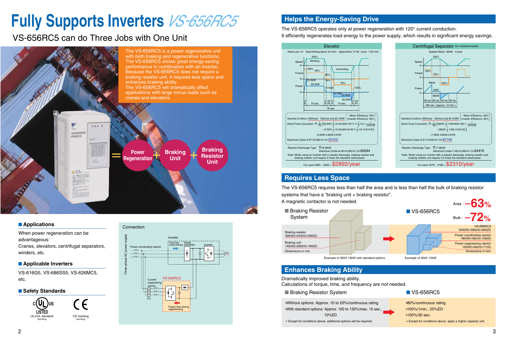
Fully Supports Inverters
VS-656RC5 can do Three Jobs with One Unit
The VS-656RC5 is a power regenerative unit
with both braking and regenerative functions.
The VS-656RC5 shows great energy-saving
performance in combination with an inverter.
Because the VS-656RC5 does not require a
braking resistor unit, it requires less space and
enhances braking ability.
The VS-656RC5 will dramatically affect
applications with large minus loads such as
cranes and elevators.
Helps the Energy-Saving Drive
The VS-656RC5 operates only at power regeneration with 120° current conduction.
It efficiently regenerates load energy to the power supply, which results in significant energy savings.
Elevator
Centrifugal Separator (for industrial waste)
Rated Load: 10 t Rated Winding Speed: 20 m/min Applied Motor: 37 kW, 6-pole, 1150 r/min
100%
Winding
150%
90%
Speed
0
Torque
0
55.5kW
33.3kW
Power
0
Unwinding
70%
30%
10%
11.1kW
130%
2
sec.
20
sec.
3.7kW
25.9kW
55.5kW
15 sec.
2
sec.
15 sec.
2
sec.
20
sec.
2
sec.
78 sec.
Operating Conditions: 5000h/year Electrical costs $0.12/kWh
Electric Power Consumption : P= (55.5kW× ×2+33.3kW×15+11.1× ×2) ×
Motor Efficiency: 90%
Inverter Efficiency: 95%
1
0.9×0.95
– (3.7kW× ×2+25.9kW×5+48.1× ×2) ×0.9×0.95
1
78
1
2
1
2
1
2
1
2
Applied Motor: 30kW, 4-pole
100%
Speed
0
Torque
0
Power
0
130%
20%
39kW
120%
6kW
36kW
180 sec. 180 sec. 180 sec.
180 sec.
180 sec. (approx. 12 min.)
Operating Conditions: 5000h/year Electrical costs $0.12/kWh
Electric Power Consumption : P= (39kW× ×180+6kW×180) ×
– (36kW× ×180) ×0.9×0.95
1
720
1
2
1
2
1
0.9×0.95
Motor Efficiency: 90%
Inverter Efficiency: 95%
Power
Regeneration
Braking
Unit
Braking
Resistor
Unit
Electrical Costs=3.67×5,000×0.12=$2202
=8.49kW–4.82kW=3.67kW
Electrical Costs=3.61×5,000×0.12=$2166
=7.46kW–3.85kW=3.61kW
Resistor Discharge Type
P=8.49kW
Electrical Costs=8.49×5,000×0.12=$5094
Note: When using an inverter with a resistor discharge, braking resistor and
braking resistor unit require 3 times the standard rated power.
You save 5094 – 2202 = $2892/year
Resistor Discharge Type
P=7.46kW
Electrical Costs=7.46×5,000×0.12=$4476
Note: When using an inverter with a resistor discharge, braking resistor and
braking resistor unit require 2.5 times the standard rated power.
You save 4476 – 2166 = $2310/year
I Applications
When power regeneration can be
advantageous:
Cranes, elevators, centrifugal separators,
winders, etc.
I Applicable Inverters
VS-616G5, VS-686SS5, VS-626MC5,
etc.
I Safety Standards
C
US
LISTED
UL/cUL standard
(pending)
CE marking
(pending)
2
Connection
l
y
p
p
u
s
r
e
w
o
p
C
A
e
s
a
h
p
-
e
e
r
h
T
Power coordinating reactor
Inverter
Power flow
during motoring
Diode
converter
Inverter
IM
VS-656RC5
Current
suppressing
reactor
FU
Power flow during
regenerating
Requires Less Space
The VS-656RC5 requires less than half the area and is less than half the bulk of braking resistor
systems that have a “braking unit + braking resistor”.
A magnetic contactor is not needed.
I Braking Resistor
System
Braking resistor
356(W)×543(H)×260(D)
Braking unit
140(W)×280(H)×160(D)
Dimensions in mm
I VS-656RC5
Bulk :
Area :
–63%
–72%
VS-656RC5
200(W)×300(H)×265(D)
Power coordinating reactor
180(W)×90(H)×100(D)
Power suppressing reactor
120(W)×90(H)×71(D)
Dimensions in mm
Example of 200V 15kW with standard options
Example of 200V 15kW
Enhances Braking Ability
Dramatically improved braking ability.
Calculations of torque, time, and frequency are not needed.
I Braking Resistor System
•Without options: Approx. 10 to 20%/continuous rating
•With standard options: Approx. 100 to 130%/max. 10 sec.,
10%ED
I VS-656RC5
•80%/continuous rating
•100%/1min., 25%ED
•150%/30 sec.
* Except for conditions above, additional options will be required.
* Except for conditions above, apply a higher capacity unit.
3
�
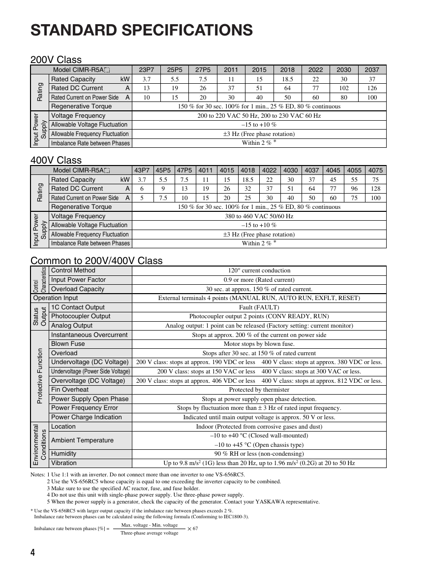
STANDARD SPECIFICATIONS
200V Class
kW
A
A
Model CIMR-R5A
Rated Capacity
Rated DC Current
Rated Current on Power Side
Regenerative Torque
Voltage Frequency
Allowable Voltage Fluctuation
Allowable Frequency Fluctuation
Imbalance Rate between Phases
23P7
3.7
13
10
25P5
5.5
19
15
27P5
7.5
26
20
2011
2015
11
37
30
15
51
40
2018
18.5
64
50
2022
2030
2037
22
77
60
30
102
80
37
126
100
150 % for 30 sec. 100% for 1 min., 25 % ED, 80 % continuous
200 to 220 VAC 50 Hz, 200 to 230 VAC 60 Hz
–15 to +10 %
±3 Hz (Free phase rotation)
Within 2 % *
g
n
i
t
a
R
r
e
w
o
P
t
u
p
n
I
l
y
p
p
u
S
400V Class
kW
A
A
Model CIMR-R5A
Rated Capacity
Rated DC Current
Rated Current on Power Side
Regenerative Torque
Voltage Frequency
Allowable Voltage Fluctuation
Allowable Frequency Fluctuation
Imbalance Rate between Phases
g
n
i
t
a
R
r
e
w
o
P
t
u
p
n
I
l
y
p
p
u
S
43P7
3.7
6
5
45P5
5.5
9
7.5
Common to 200V/400V Class
4022
4030
4011
4015
47P5
7.5
13
10
150 % for 30 sec. 100% for 1 min., 25 % ED, 80 % continuous
4018
18.5
32
25
11
19
15
15
26
20
22
37
30
4037
4045
30
51
40
37
64
50
45
77
60
4055
4075
55
96
75
75
128
100
380 to 460 VAC 50/60 Hz
–15 to +10 %
±3 Hz (Free phase rotation)
Within 2 % *
120° current conduction
0.9 or more (Rated current)
30 sec. at approx. 150 % of rated current.
s
c
i
t
s
i
r
e
t
c
a
r
a
h
C
l
o
r
t
n
o
C
Control Method
Input Power Factor
Overload Capacity
Operation Input
s
u
t
t
a
S
t
t
u
p
u
O
n
o
i
t
c
n
u
F
e
v
i
t
c
e
t
o
r
P
l
a
t
n
e
m
n
o
r
i
v
n
E
s
n
o
i
t
i
d
n
o
C
1C Contact Output
Photocoupler Output
Analog Output
Instantaneous Overcurrent
Blown Fuse
Overload
Undervoltage (DC Voltage)
Undervoltage (Power Side Voltage)
Overvoltage (DC Voltage)
Fin Overheat
Power Supply Open Phase
Power Frequency Error
Power Charge Indication
Location
Ambient Temperature
Humidity
Vibration
External terminals 4 points (MANUAL RUN, AUTO RUN, EXFLT, RESET)
Fault (FAULT)
Photocoupler output 2 points (CONV READY, RUN)
Analog output: 1 point can be released (Factory setting: current monitor)
Stops at approx. 200 % of the current on power side
Motor stops by blown fuse.
Stops after 30 sec. at 150 % of rated current
200 V class: stops at approx. 190 VDC or less 400 V class: stops at approx. 380 VDC or less.
200 V class: stops at 150 VAC or less 400 V class: stops at 300 VAC or less.
200 V class: stops at approx. 406 VDC or less 400 V class: stops at approx. 812 VDC or less.
Protected by thermister
Stops at power supply open phase detection.
Stops by fluctuation more than ± 3 Hz of rated input frequency.
Indicated until main output voltage is approx. 50 V or less.
Indoor (Protected from corrosive gases and dust)
–10 to +40 °C (Closed wall-mounted)
–10 to +45 °C (Open chassis type)
90 % RH or less (non-condensing)
Up to 9.8 m/s2 (1G) less than 20 Hz, up to 1.96 m/s2 (0.2G) at 20 to 50 Hz
Notes: 1 Use 1:1 with an inverter. Do not connect more than one inverter to one VS-656RC5.
2 Use the VS-656RC5 whose capacity is equal to one exceeding the inverter capacity to be combined.
3 Make sure to use the specified AC reactor, fuse, and fuse holder.
4 Do not use this unit with single-phase power supply. Use three-phase power supply.
5 When the power supply is a generator, check the capacity of the generator. Contact your YASKAWA representative.
* Use the VS-656RC5 with larger output capacity if the imbalance rate between phases exceeds 2 %.
Imbalance rate between phases can be calculated using the following formula (Conforming to IEC1800-3).
Imbalance rate between phases [%] =
Max. voltage - Min. voltage
Three-phase average voltage
× 67
4
�
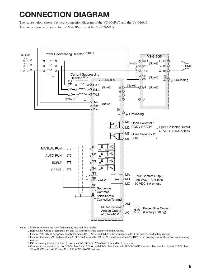
CONNECTION DIAGRAM
The figure below shows a typical connection diagram of the VS-656RC5 and the VS-616G5.
The connection is the same for the VS-686SS5 and the VS-626MC5.
MCCB
Power Coordinating Reactor (Note1)
Current Suppressing
Reactor (Note1)
FU
(Note1)
MANUAL RUN
AUTO RUN
EXFLT
RESET
VS-656RC5
R/L1
S/L2
T/L3
r1/l11
s1/l21
t1/l31
(Note3)
(Note4)
g
g
f
f
(Note2)
VS-616G5
R/L1
S/L2
T/L3
r/l1
s/l2
(Note3)
U/T1
V/T2
W/T3
(Note4)
(Note5)
g1
(Note6)
IM
Grounding
f
Grounding
M1 Open Collector 1
M2
CONV READY
M3
M4
Open Collector 2
RUN
Open Collector Output
48 VDC 58 mA or less
S1
S2
S3
S4
SS
SP
SC
E
+24 V
Sequence
Common
Shield Sheath
Connection Terminal
Multi-functional
Analog Output
–10 to +10 V
MA
MB
MC
AM
AC
Fault Contact Output
250 VAC 1 A or less
30 VDC 1 A or less
+
AM
–
Power Side Current
(Factory Setting)
Notes: 1 Make sure to use the specified reactor, fuse and fuse holder.
2 Remove the wiring of terminals r/l1 and s/l2 since they were connected at the factory.
3 Connect VS-616G5 AC power supply terminals R/L1, S/L2, and T/L3 to the secondary side of the power coordinating reactor.
4 Connect terminals r/l1, and s/l2 of VS-616G5, and terminals r1/l11, s1/l21, and t1/l31 of VS-656RC5 to the primary side of the power coordinating
reactor.
5 DC bus wiring (g1 – g, f – f) between VS-616G5 and VS-656RC5 should be 5 m or less.
6 Connect to the terminal g1 for 200 V class 0.4 to 22 kW, and 400 V class 0.4 to 45 kW VS-616G5 inverters. Use terminal g3 for 200 V class
30 to 37 kW, and 400 V class 55 to 75 kW VS-616G5 inverters.
5
�
S1
S2
S3
S4
SC
SS
SP
M1–M2
M3–M4
MA–MC
MB–MC
Sequence Input
Photocoupler
Output
Relay Output
MANUAL RUN *1
AUTO RUN *2
EXFLT
RESET
Sequence Common
Photocoupler Internal Common
Sequence +24 V Power Supply
CONV READY
RUN
FAULT Output
(Transfer Contact)
Run when CLOSED, stops when OPEN
Auto run (regenerative operation) when CLOSED
External fault when CLOSED
Fault reset when CLOSED
Closed when VS-656RC5 is READY
CLOSE during run
Outputs when a fault is detected.
Terminal MA-MC : Closed during fault detection
Terminal MB-MC : Open during fault detection
5 V : 100 % of rated input current
Signal Level
24 VDC 8 mA
Photocoupler
isolation
48 VDC 80 mA
or less
250 VAC 1 A or less
30 VDC 1 A or less
–10 to +10 VDC
2 mA or less
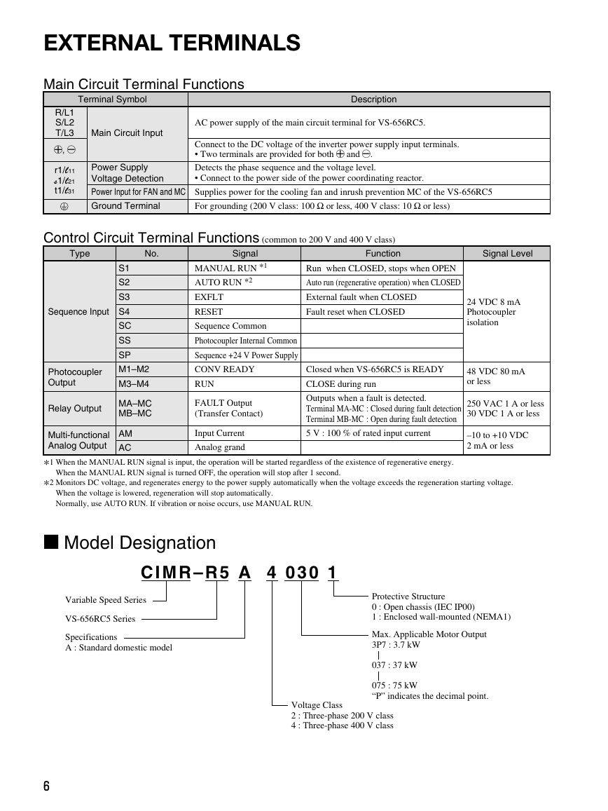
EXTERNAL TERMINALS
Main Circuit Terminal Functions
Terminal Symbol
Description
R/L1
S/L2
T/L3
g, f
r1/l11
s1/l21
t1/l31
Main Circuit Input
Power Supply
Voltage Detection
Power Input for FAN and MC
Ground Terminal
AC power supply of the main circuit terminal for VS-656RC5.
Connect to the DC voltage of the inverter power supply input terminals.
• Two terminals are provided for both g and f.
Detects the phase sequence and the voltage level.
• Connect to the power side of the power coordinating reactor.
Supplies power for the cooling fan and inrush prevention MC of the VS-656RC5
For grounding (200 V class: 100 Ω or less, 400 V class: 10 Ω or less)
Control Circuit Terminal Functions (common to 200 V and 400 V class)
Function
Signal
Type
No.
AM
AC
Multi-functional
Analog Output
*1 When the MANUAL RUN signal is input, the operation will be started regardless of the existence of regenerative energy.
*2 Monitors DC voltage, and regenerates energy to the power supply automatically when the voltage exceeds the regeneration starting voltage.
When the MANUAL RUN signal is turned OFF, the operation will stop after 1 second.
Input Current
Analog grand
When the voltage is lowered, regeneration will stop automatically.
Normally, use AUTO RUN. If vibration or noise occurs, use MANUAL RUN.
I Model Designation
C I M R – R 5 A 4 0 3 0 1
Variable Speed Series
VS-656RC5 Series
Specifications
A : Standard domestic model
6
Protective Structure
0 : Open chassis (IEC IP00)
1 : Enclosed wall-mounted (NEMA1)
Max. Applicable Motor Output
3P7 : 3.7 kW
037 : 37 kW
075 : 75 kW
“P” indicates the decimal point.
Voltage Class
2 : Three-phase 200 V class
4 : Three-phase 400 V class
�
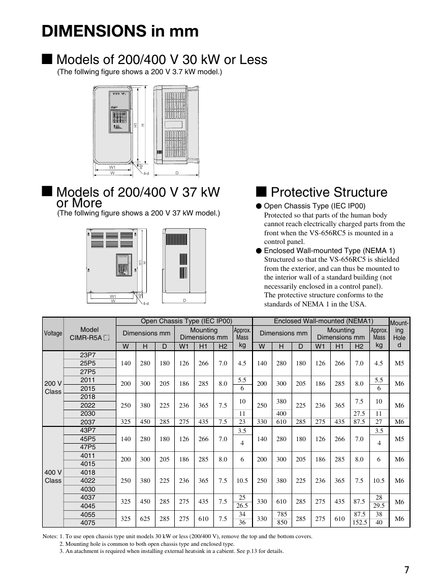
DIMENSIONS in mm
I Models of 200/400 V 30 kW or Less
(The follwing figure shows a 200 V 3.7 kW model.)
1
H
H
W1
W
2
H
4-d
D
I Models of 200/400 V 37 kW
or More
(The follwing figure shows a 200 V 37 kW model.)
1
H
H
W1
W
2
H
4-d
D
I Protective Structure
• Open Chassis Type (IEC IP00)
Protected so that parts of the human body
cannot reach electrically charged parts from the
front when the VS-656RC5 is mounted in a
control panel.
• Enclosed Wall-mounted Type (NEMA 1)
Structured so that the VS-656RC5 is shielded
from the exterior, and can thus be mounted to
the interior wall of a standard building (not
necessarily enclosed in a control panel).
The protective structure conforms to the
standards of NEMA 1 in the USA.
Voltage
Model
CIMR-R5A
Dimensions mm
Mounting
Dimensions mm
H2
H1
D W1
W
H
Dimensions mm
W
H
Mounting
Dimensions mm
H2
H1
D W1
Mount-
ing
Hole
d
Approx.
Mass
kg
Open Chassis Type (IEC IP00)
Enclosed Wall-mounted (NEMA1)
Approx.
Mass
kg
4.5
5.5
6
10
11
23
3.5
4
6
200 V
Class
400 V
Class
23P7
25P5
27P5
2011
2015
2018
2022
2030
2037
43P7
45P5
47P5
4011
4015
4018
4022
4030
4037
4045
4055
4075
140
280
180
126
266
7.0
200
300
205
186
285
8.0
250
380
225
236
365
325
450
285
275
435
7.5
7.5
140
280
180
126
266
7.0
200
300
205
186
285
8.0
140
280
180
126
266
7.0
4.5
M5
200
300
205
186
285
8.0
250
330
380
400
610
225
236
365
285
275
435
7.5
27.5
87.5
140
280
180
126
266
7.0
200
300
205
186
285
8.0
5.5
6
10
11
27
3.5
4
6
M6
M6
M6
M5
M6
250
380
225
236
365
7.5
10.5
250
380
225
236
365
7.5
10.5 M6
325
450
285
275
435
7.5
325
625
285
275
610
7.5
25
26.5
34
36
330
610
285
275
435
87.5
330
785
850
285
275
610
87.5
152.5
28
29.5
38
40
M6
M6
Notes: 1. To use open chassis type unit models 30 kW or less (200/400 V), remove the top and the bottom covers.
2. Mounting hole is common to both open chassis type and enclosed type.
3. An atachment is required when installing external heatsink in a cabient. See p.13 for details.
7
�
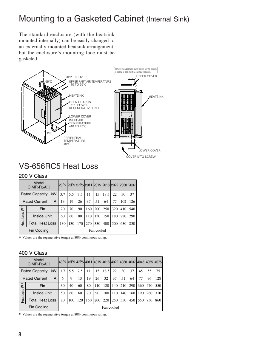
Mounting to a Gasketed Cabinet (Internal Sink)
The standard enclosure (with the heatsink
mounted internally) can be easily changed to
an externally mounted heatsink arrangement,
but the enclosure’s mounting face must be
gasketed.
55°C
UPPER COVER
UPPER PART AIR TEMPERATURE
–10 TO 55°C
Remove the upper and lower covers for the models
of 30 kW or less in 200 V and 400 V classes.
UPPER COVER
HEATSINK
OPEN CHASSIS
TYPE POWER
REGENERATIVE UNIT
LOWER COVER
INLET AIR
TEMPERATURE
–10 TO 45°C
45°C
PERIPHERAL
TEMPERATURE
40°C
HEATSINK
LOWER COVER
COVER MTG SCREW
VS-656RC5 Heat Loss
200 V Class
Model
CIMR-R5A=
23P7 25P5 27P5 2011 2015 2018 2022 2030 2037
Rated Capacity kW
3.7
5.5
7.5
13
70
60
19
70
60
26
90
80
11
37
15
51
18.5
64
22
77
30
37
102
126
160
200
250
320
410
540
110
130
150
180
220
290
Rated Current A
Fin
Inside Unit
*
W
s
s
o
L
t
a
e
H
Total Heat Loss
130
130
170
270
330
400
500
630
830
Fin Cooling
Fan cooled
* Values are the regenerative torque at 80% continuous rating.
400 V Class
Model
CIMR-R5A=
43P7 45P5 47P5 4011 4015 4018 4022 4030 4037
4045 4055 4075
Rated Capacity kW
3.7
5.5
7.5
Rated Current A
*
W
s
s
o
L
t
a
e
H
Fin
Inside Unit
Total Heat Loss
Fin Cooling
6
30
50
80
11
19
80
70
15
26
18.5
32
22
37
30
51
37
64
45
77
55
96
75
128
110
120
140
210
290
360
470
550
90
100
110
140
160
190
260
310
9
40
60
13
60
60
100
120
150
200
220
250
350
450
550
730
860
Fan cooled
* Values are the regenerative torque at 80% continuous rating.
8
�
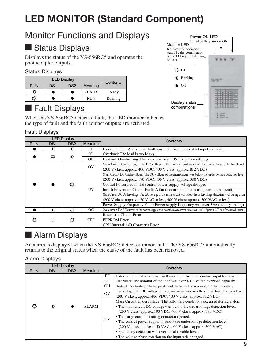
LED MONITOR (Standard Component)
Monitor Functions and Displays
I Status Displays
Displays the status of the VS-656RC5 and operates the
photocoupler outputs.
Status Displays
RUN
LED Display
DS2
DS1
Meaning
READY
RUN
Contents
Ready
Running
I Fault Displays
When the VS-656RC5 detects a fault, the LED monitor indicates
the type of fault and the fault contact outputs are activated.
Fault Displays
Power ON LED
Lit when the power is ON
Monitor LED
Indicates the operation
status by the combination
of the LEDs (Lit, Blinking,
or Off)
Lit
Blinking
Off
Display status
combinations
RUN
LED Display
DS2
DS1
Meaning
Contents
EF
OL
OH
OV
UV
OC
CPF
External Fault: An external fault was input from the contact input terminal.
Overload: The load is too heavy.
Heatsink Overheating: Heatsink was over 105°C (factory setting).
Main Circuit Overvoltage: The DC voltage of the main circuit was over the overvoltage detection level.
(200 V class: approx. 406 VDC, 400 V class: approx. 812 VDC)
Main Circuit DC Undervoltage: The DC voltage of the main circuit was below the undervoltage detection level.
(200 V class: approx. 190 VDC, 400 V class: approx. 380 VDC)
Control Power Fault: The control power supply voltage dropped.
Inrush Prevention Circuit Fault: A fault occurred in the inrush prevention circuit.
Main Circuit AC Undervoltage: The AC voltage of the main circuit was below the undervoltage detection level during a run.
(200 V class: approx. 150 VAC or less, 400 V class: approx. 300 VAC or less)
Power Supply Frequency Fault: Power supply frequency was over 3Hz (factory setting)
Overcurrent: The AC current of the power supply was over the overcurrent detection level. (Approx. 200 % of the rated current)
Baseblock Circuit Error
EEPROM Error
CPU Internal A/D Converter Error
I Alarm Displays
An alarm is displayed when the VS-656RC5 detects a minor fault. The VS-656RC5 automatically
returns to the original status when the cause of the fault has been removed.
Alarm Displays
RUN
LED Display
DS2
DS1
Meaning
Contents
ALARM
EF
OL
OH
OV
External Fault: An external fault was input from the contact input terminal.
Overload: The amount of the load was over 80 % of the overload capacity.
Heatsink Overheating: The temperature of the heatsink was over 90 °C (factory setting).
Overvoltage: The DC voltage of the main circuit was over the overvoltage detection level.
(200 V class: approx. 406 VDC, 400 V class: approx. 812 VDC)
Main Circuit Undervoltage: The following conditions occurred during a stop.
• The main circuit DC voltage was below the undervoltage detection level.
(200 V class: approx. 190 VDC, 400 V class: approx. 380 VDC)
UV
• The surge current limiting contactor opened.
• The control power supply is below the undervoltage detection level.
(200 V class: approx. 150 VAC, 400 V class: approx. 300 VAC)
• Frequency detection was over the allowable level.
• The voltage phase rotation on the input side changed.
9
�



 2023年江西萍乡中考道德与法治真题及答案.doc
 2012年重庆南川中考生物真题及答案.doc
 2013年江西师范大学地理学综合及文艺理论基础考研真题.doc
 2020年四川甘孜小升初语文真题及答案I卷.doc
 2020年注册岩土工程师专业基础考试真题及答案.doc
 2023-2024学年福建省厦门市九年级上学期数学月考试题及答案.doc
 2021-2022学年辽宁省沈阳市大东区九年级上学期语文期末试题及答案.doc
 2022-2023学年北京东城区初三第一学期物理期末试卷及答案.doc
 2018上半年江西教师资格初中地理学科知识与教学能力真题及答案.doc
 2012年河北国家公务员申论考试真题及答案-省级.doc
 2020-2021学年江苏省扬州市江都区邵樊片九年级上学期数学第一次质量检测试题及答案.doc
 2022下半年黑龙江教师资格证中学综合素质真题及答案.doc