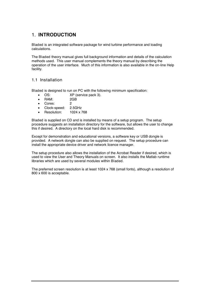
1. INTRODUCTION
1.1 Installation
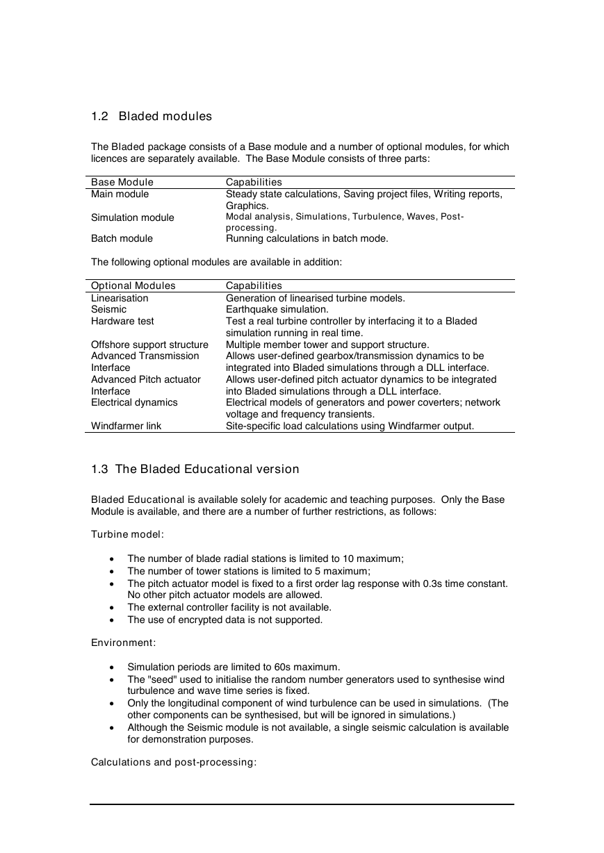
1.2 Bladed modules
1.3 The Bladed Educational version
1.4 The Bladed Demonstration version
1.5 Support
1.6 Documentation
1.7 Acknowledgements
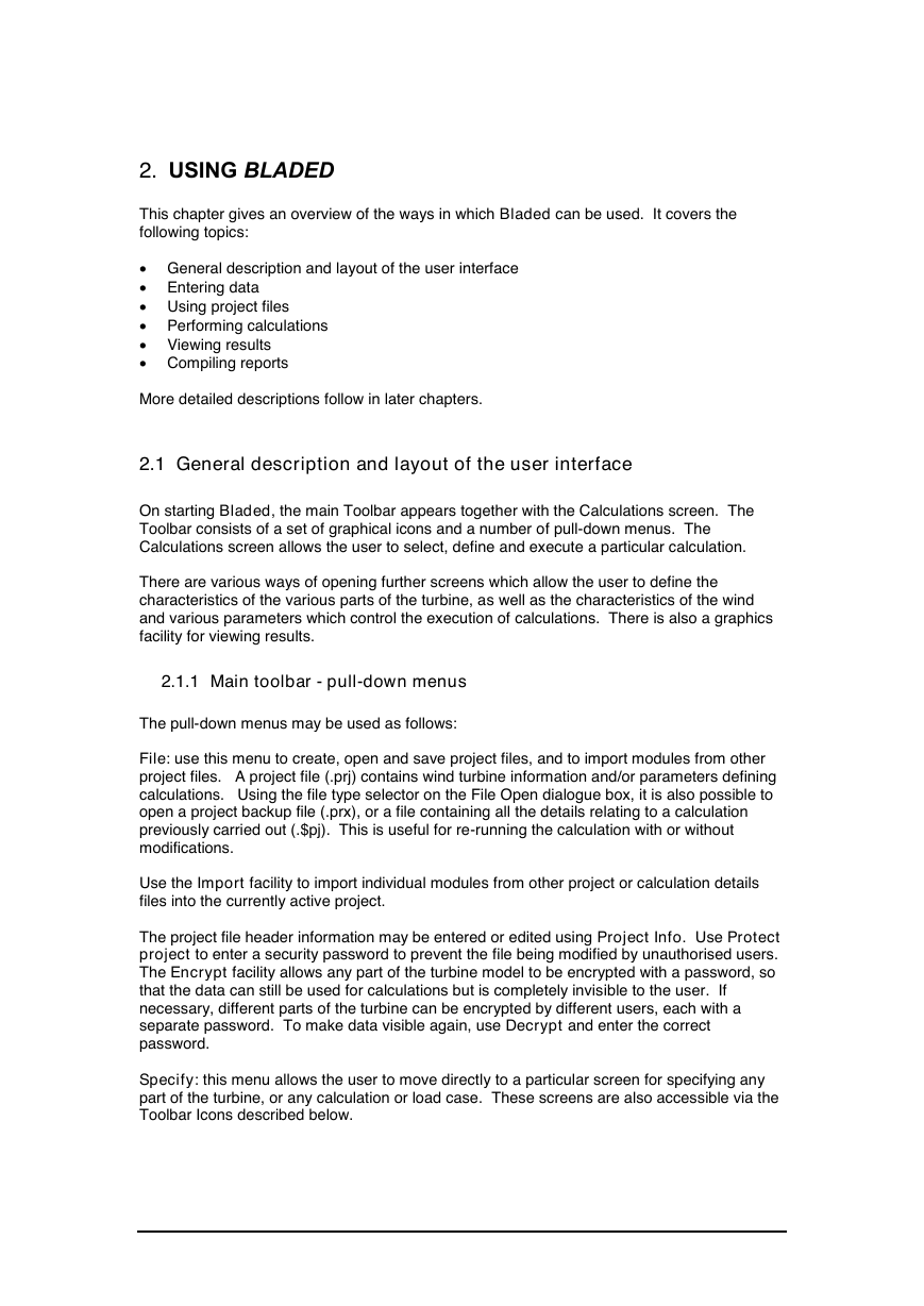
2. USING BLADED
2.1 General description and layout of the user interface
2.1.1 Main toolbar - pull-down menus
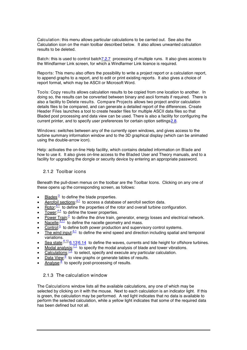
2.1.2 Toolbar icons
2.1.3 The calculation window
2.1.4 Sequence of operations
2.2 Entering data
2.3 Using project files
2.4 Performing calculations
2.5 Viewing results
2.6 Compiling reports
2.7 Data Encryption
2.8 User preferences
2.8.1 Standard tab
2.8.2 Net dongle settings tab
2.9 Context-sensitive help
2.10 Dongles
2.11 Component download
3. DEFINING THE TURBINE BLADES
3.1 Choosing blade stations
3.2 Blade geometry
3.3 Blade mass distribution
3.3.1 Distributed mass
3.3.2 Point masses
3.3.3 Vibration dampers
3.3.4 Blade icing
3.4 Blade stiffness distribution
3.5 Additional degrees of freedom
3.6 Conversion from older versions of Bladed
3.7 Aerofoil sections
3.8 Aerofoil datasets
3.8.1 Defining aerofoil datasets
3.8.2 Importing a dataset
3.8.3 Adding a new dataset manually or via the clipboard
3.8.4 Editing an existing dataset
3.8.5 Removing a dataset
3.8.6 Viewing aerofoil data graphically
3.9 Format of ASCII aerofoil files
3.10 Defining normal aerofoil sections
3.11 Defining aileron sections
4. DEFINING THE REST OF THE TURBINE
4.1 Defining the rotor
4.2 Defining the hub
4.3 Teeter restraint
4.4 Defining the tower
4.4.1 Monopile Tower
4.4.2 Multi-member tower
4.4.3 Flanges and point masses
4.4.4 Vibration dampers
4.4.5 Environment
4.4.6 Foundations
4.4.7 Moorings
4.5 Defining the power train
4.6 Transmission
4.6.1 Locked speed model
4.6.2 Dynamic model
4.6.3 External DLL for transmission dynamics
4.7 Drive train mountings
4.8 Generator
4.8.1 Induction generator
4.8.2 Variable speed generator models
4.8.3 Variable speed mechanical model
4.8.4 Preliminary design tool for variable speed electrical models
4.8.5 Synchronous generator with fully rated converter
4.8.6 Doubly fed induction generator model
4.8.7 Variable slip generator
4.8.8 User-defined generator model
4.8.9 Drive train damping feedback
4.9 Energy losses
4.9.1 Mechanical losses
4.9.2 Electrical losses
4.10 The Electrical Network
4.11 The nacelle
5. CONTROL SYSTEMS
5.1 Fixed Speed Stall Regulated Control
5.2 The fixed speed pitch regulated controller
5.2.1 Steady state parameters
5.2.2 Dynamic parameters
5.3 The variable speed stall regulated controller
5.3.1 Steady state parameters
5.3.2 Dynamic parameters
5.4 The variable speed pitch regulated controller
5.4.1 Steady state parameters
5.4.2 Dynamic parameters
5.5 PI control
5.6 Gain scheduling
5.7 Auto tune for internal PI controllers
5.8 Variable speed control below rated
5.8.1 Optimal tip speed ratio
5.8.2 Look-up table
5.8.3 Automatic calculation of optimal torque-speed curve
5.8.4 Other parameters
5.8.5 Control in the variable slip case
5.9 User-defined controllers
5.9.1 Using a user-defined controller
5.9.2 Signal noise and discretisation
5.10 Transducers
5.11 The Pitch Actuator
5.11.1 Safety System Pitch Action
5.11.2 Output Variables
5.12 The shaft brake
5.13 Start-up sequence
5.14 Normal stop sequence
5.15 Emergency stop sequence
5.16 Idling conditions
5.17 Parked conditions
5.18 Yaw control
5.18.1 Yaw Dynamics
5.18.2 Active Yaw
5.19 Safety System
5.19.1 Safety System Circuits
5.19.2 Safety System Pitch Action
5.19.3 Safety System Trips
6. DEFINING THE ENVIRONMENT
6.1 Defining the wind
6.2 Wind shear
6.3 Tower shadow
6.4 Upwind turbine wake
6.5 No time variation of wind speed
6.6 Single point wind history
6.7 3D turbulent wind
6.8 Transients
6.9 Definition of wind direction
6.10 Generating turbulent wind fields
6.10.1 Defining turbulence characteristics
6.10.2 Advanced options
6.10.3 Generating the turbulence field
6.11 Annual wind distribution
6.12 Defining Waves
6.12.1 None (no waves)
6.12.2 Irregular waves
6.12.3 Constrained waves
6.12.4 Regular waves
6.13 Defining Currents
6.13.1 Near-surface current
6.13.2 Sub-surface current
6.13.3 Near-shore current
6.14 Tide height
6.15 Scatter diagram
6.16 Earthquakes
6.16.1 Generating earthquake time histories
6.17 Point loading
7. EXECUTING WIND TURBINE CALCULATIONS
7.1 Modal analysis
7.1.1 Defining the modes
7.1.2 Performing the calculation
7.1.3 The modal frequencies
7.2 The calculations screen
7.2.1 Calculations available
7.2.2 Data required for calculations
7.2.3 Calculation options
7.2.4 Specifying outputs
7.2.5 Calculation parameters
7.2.6 Executing a calculation
7.2.7 Batch processing
7.2.8 Retrieving calculation details
7.3 Steady calculations
7.4 Simulations
7.5 Calculation parameters
7.6 Aerodynamic information calculation
7.7 Performance coefficients calculation
7.8 Steady power curve calculation
7.9 Steady operational loads calculation
7.10 Steady parked loads calculation
7.11 Model linearisation calculation
7.11.1 Selection of model features for linearisations and Campbell diagram
7.12 Electrical performance
7.13 Pitch and speed schedule
7.14 Simulation control
7.15 Initial conditions
7.16 Hardware test simulation
7.17 Aerodynamic models
7.18 Physical constants
7.19 Safety factors
7.20 Imbalances
7.21 Turbine Faults
7.21.1 Pitch faults
7.21.2 Generator and network faults
7.21.3 Yaw faults
7.21.4 Transducer faults
7.22 Controlling the calculation outputs
7.22.1 Blade outputs
7.22.2 Tower outputs
7.22.3 Other outputs
7.22.4 Co-ordinate systems
7.22.5 Exceptions to the use of the ‘GL’ co-ordinate system
7.23 Specifying calculation options
7.24 Multiple calculation setup
8. POST-PROCESSING
8.1 Basic statistics
8.2 Fourier harmonics
8.3 Periodic components
8.4 Extreme predictions
8.5 Auto spectrum
8.5.1 Options for spectral analysis
8.6 Cross spectrum
8.7 Probability density
8.8 Peak value analysis
8.9 Level crossing analysis
8.10 Rainflow cycle counting
8.11 Fatigue damage estimation
8.12 Setting bin limits
8.13 Annual energy yield
8.14 Channel Combination and Tabulation
8.14.1 Multiple processing option – Channel combination
8.14.2 Multiple processing option - Tabulation
8.14.3 Multiple processing option – Matrix combination
8.14.4 Multiple processing option – Old Style channel combination
8.14.5 Single channel combinations
8.15 Multiple Processing
8.16 Ultimate Loads
8.17 Ultimate Load Cases
8.18 Flicker
8.19 Linear Model
8.20 Extreme load extrapolation
8.21 Offshore Code Checking
8.21.1 Bladed-ANSYS® link
8.21.2 Bladed-SACS link
8.22 Data channel selection
8.22.1 Selecting independent variables
8.22.2 Messages and further information
8.22.3 Deleting information
9. GRAPHICAL DATA VIEW FACILITY
9.1 Graphs of several variables
9.2 Graph styles
9.3 Grids and logarithmic axes
9.4 Units
9.5 Axis limits
9.6 Graph titles
9.7 Graph legends and line styles
9.8 Cross-plots
9.9 Tabular output of results
9.10 Refreshing graphs
9.11 Graph configurations
9.12 Multiple Plotting and Tabulation
9.12.1 Graph configurations
9.12.2 Replacing variables
9.12.3 Replacing runs
9.12.4 Sequence Control
9.12.5 Tabulation of Ultimate Loads
9.12.6 Output
10. REPORTING
10.1 Project reports
10.2 Calculation reports
10.3 Adding calculation results to a report
10.4 Editing and printing reports
10.5 Linked graphs
10.6 LM Uploader
11. THE WINDFARMER LINK MODULE
11.1 The Windfarmer output file
11.2 The wind file template
11.3 The turbine model template
11.4 The fatigue processing template
11.5 The Ranking Calculation
11.6 Sectors and Options
11.6.1 Direction sectors
11.6.2 Overriding values from Windfarmer
11.7 Output folders and file naming convention
11.8 Image viewer
APPENDIX A Communication Between Bladed And External Controllers
A.1 The Bladed External Controller API
A.2 Simulation Status
A.3 Sending messages to the simulation
A.4 Pitch and torque override
A.5 Sending logging output to Bladed
APPENDIX B Example External Controller Code In Selected Languages
B.1 Simple example of DLL code written in C
B.2 Simple example of DLL code written in FORTRAN 90
APPENDIX C Gearbox DLL Interface Specification
C.1 1 DOF Gearbox DLL Interface
C.2 6 DOF Gearbox DLL Interface
APPENDIX D Generator DLL Interface Specification
APPENDIX E Pitch actuator DLL Interface Specification
E.1 Continuous DLL interface:
E.2 Discrete DLL interface:
References




 2023年江西萍乡中考道德与法治真题及答案.doc
 2012年重庆南川中考生物真题及答案.doc
 2013年江西师范大学地理学综合及文艺理论基础考研真题.doc
 2020年四川甘孜小升初语文真题及答案I卷.doc
 2020年注册岩土工程师专业基础考试真题及答案.doc
 2023-2024学年福建省厦门市九年级上学期数学月考试题及答案.doc
 2021-2022学年辽宁省沈阳市大东区九年级上学期语文期末试题及答案.doc
 2022-2023学年北京东城区初三第一学期物理期末试卷及答案.doc
 2018上半年江西教师资格初中地理学科知识与教学能力真题及答案.doc
 2012年河北国家公务员申论考试真题及答案-省级.doc
 2020-2021学年江苏省扬州市江都区邵樊片九年级上学期数学第一次质量检测试题及答案.doc
 2022下半年黑龙江教师资格证中学综合素质真题及答案.doc