logo资料库

Intel主板-D845EBG2说明书.pdf

第1页 / 共78页
第2页 / 共78页
第3页 / 共78页
第4页 / 共78页
第5页 / 共78页
第6页 / 共78页
第7页 / 共78页
第8页 / 共78页
资料共78页,剩余部分请下载后查看
Intel® Desktop Boards D845EPT2 and D845EBG2 Product Guide
Disclaimer
Contents
1 Desktop Board Features
Desktop Board Components
Processor
Main Memory
Intel® 845E Chipset
Intel® 82845E Memory Controller Hub (MCH)
Intel® 82801DB I/O Controller Hub (ICH4)
Firmware Hub (FWH)
Input/Output (I/O) Controller
Audio Subsystem
LAN Subsystem (Optional)
LAN Subsystem Software
RJ-45 LAN Connector LEDs
Hi-Speed USB 2.0 Support
Enhanced IDE Interface
Expansion Slots
Accelerated Graphics Port (AGP)
Communication and Networking Riser (CNR) (Optional)
BIOS
PCI Auto Configuration
IDE Auto Configuration
Security Passwords
Power Management Features
ACPI
Suspend to RAM (Instantly Available PC Technology)
Hardware Management
Power Connectors
Fan Connectors
Resume on Ring
Wake from USB
Wake from PS/2 Keyboard/Mouse
PME# Wakeup Support
Speaker
Battery
Real-Time Clock
2 Installing and Replacing Desktop Board Components
Before You Begin
Installing the I/O Shield
Installing and Removing the Desktop Board
Installing and Removing a Processor
Installing a Processor
Installing the Processor Fan Heat Sink
Connecting the Processor Fan Heat Sink Cable
Removing a Processor
Installing and Removing Memory
Installing DIMMs
Removing DIMMs
Installing and Removing the AGP Card
Installing an AGP Card
Removing the AGP Card
Connecting the IDE Cable
Setting the BIOS Configuration Jumper Block
Installing the Front Panel Audio Solution
Clearing Passwords
Replacing the Battery
3 Updating the BIOS
Updating the BIOS with the Intel® Express BIOS Update Utility
Updating the BIOS with the Intel® Flash Memory Update Utility
Obtaining the BIOS Update File
Updating the BIOS
Recovering the BIOS
4 Using the BIOS Setup Program
Maintenance Menu
Extended Configuration Submenu
Main Menu
Advanced Menu
PCI Configuration Submenu
Boot Configuration Submenu
Peripheral Configuration Submenu
IDE Configuration Submenu
Primary/Secondary IDE Master/Slave Submenus
Floppy Configuration Submenu
Event Log Configuration Submenu
Video Configuration Submenu
USB Configuration Submenu
Security Menu
Power Menu
ACPI Submenu
Boot Menu
Boot Device Priority Submenu
Hard Disk Drives Submenu
Removable Devices Submenu
ATAPI CD-ROM Drives
Exit Menu
5 Technical Reference
Connectors
Back Panel Connectors
Midboard Connectors
Audio Connectors
Power and Hardware Connectors
Add-In Card and Peripheral Interface Connectors
Front Panel Headers
Desktop Board Resources
Memory Map
DMA Channels
Interrupts
A Error Messages and Indicators
BIOS Beep Codes
BIOS Error Messages
B Regulatory Compliance
Safety Regulations
EMC Regulations
Product Certification Markings
Installation Precautions
Installation Instructions
Ensure Electromagnetic Compatibility (EMC) Compliance
Chassis and Component Certifications
Prevent Power Supply Overload
Place Battery Marking
Use Only for Intended Applications
Intel® Desktop Boards D845EPT2 and D845EBG2 Product Guide Order Number: A84611-001
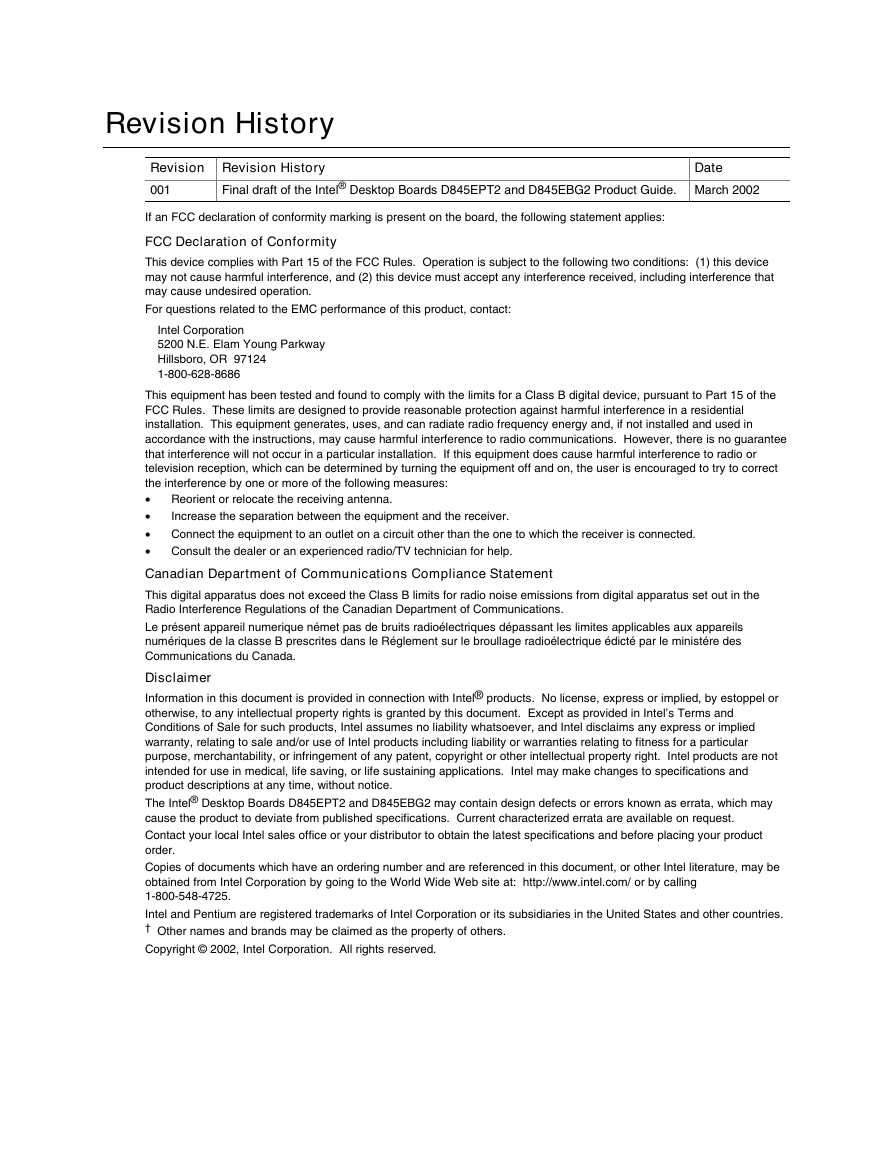
Revision History Revision Revision History 001 Date Final draft of the Intel® Desktop Boards D845EPT2 and D845EBG2 Product Guide. March 2002 If an FCC declaration of conformity marking is present on the board, the following statement applies: FCC Declaration of Conformity This device complies with Part 15 of the FCC Rules. Operation is subject to the following two conditions: (1) this device may not cause harmful interference, and (2) this device must accept any interference received, including interference that may cause undesired operation. For questions related to the EMC performance of this product, contact: Intel Corporation 5200 N.E. Elam Young Parkway Hillsboro, OR 97124 1-800-628-8686 This equipment has been tested and found to comply with the limits for a Class B digital device, pursuant to Part 15 of the FCC Rules. These limits are designed to provide reasonable protection against harmful interference in a residential installation. This equipment generates, uses, and can radiate radio frequency energy and, if not installed and used in accordance with the instructions, may cause harmful interference to radio communications. However, there is no guarantee that interference will not occur in a particular installation. If this equipment does cause harmful interference to radio or television reception, which can be determined by turning the equipment off and on, the user is encouraged to try to correct the interference by one or more of the following measures: • • • • Reorient or relocate the receiving antenna. Increase the separation between the equipment and the receiver. Connect the equipment to an outlet on a circuit other than the one to which the receiver is connected. Consult the dealer or an experienced radio/TV technician for help. Canadian Department of Communications Compliance Statement This digital apparatus does not exceed the Class B limits for radio noise emissions from digital apparatus set out in the Radio Interference Regulations of the Canadian Department of Communications. Le présent appareil numerique német pas de bruits radioélectriques dépassant les limites applicables aux appareils numériques de la classe B prescrites dans le Réglement sur le broullage radioélectrique édicté par le ministére des Communications du Canada. Disclaimer Information in this document is provided in connection with Intel® products. No license, express or implied, by estoppel or otherwise, to any intellectual property rights is granted by this document. Except as provided in Intel’s Terms and Conditions of Sale for such products, Intel assumes no liability whatsoever, and Intel disclaims any express or implied warranty, relating to sale and/or use of Intel products including liability or warranties relating to fitness for a particular purpose, merchantability, or infringement of any patent, copyright or other intellectual property right. Intel products are not intended for use in medical, life saving, or life sustaining applications. Intel may make changes to specifications and product descriptions at any time, without notice. The Intel® Desktop Boards D845EPT2 and D845EBG2 may contain design defects or errors known as errata, which may cause the product to deviate from published specifications. Current characterized errata are available on request. Contact your local Intel sales office or your distributor to obtain the latest specifications and before placing your product order. Copies of documents which have an ordering number and are referenced in this document, or other Intel literature, may be obtained from Intel Corporation by going to the World Wide Web site at: http://www.intel.com/ or by calling 1-800-548-4725. Intel and Pentium are registered trademarks of Intel Corporation or its subsidiaries in the United States and other countries. † Other names and brands may be claimed as the property of others. Copyright © 2002, Intel Corporation. All rights reserved.
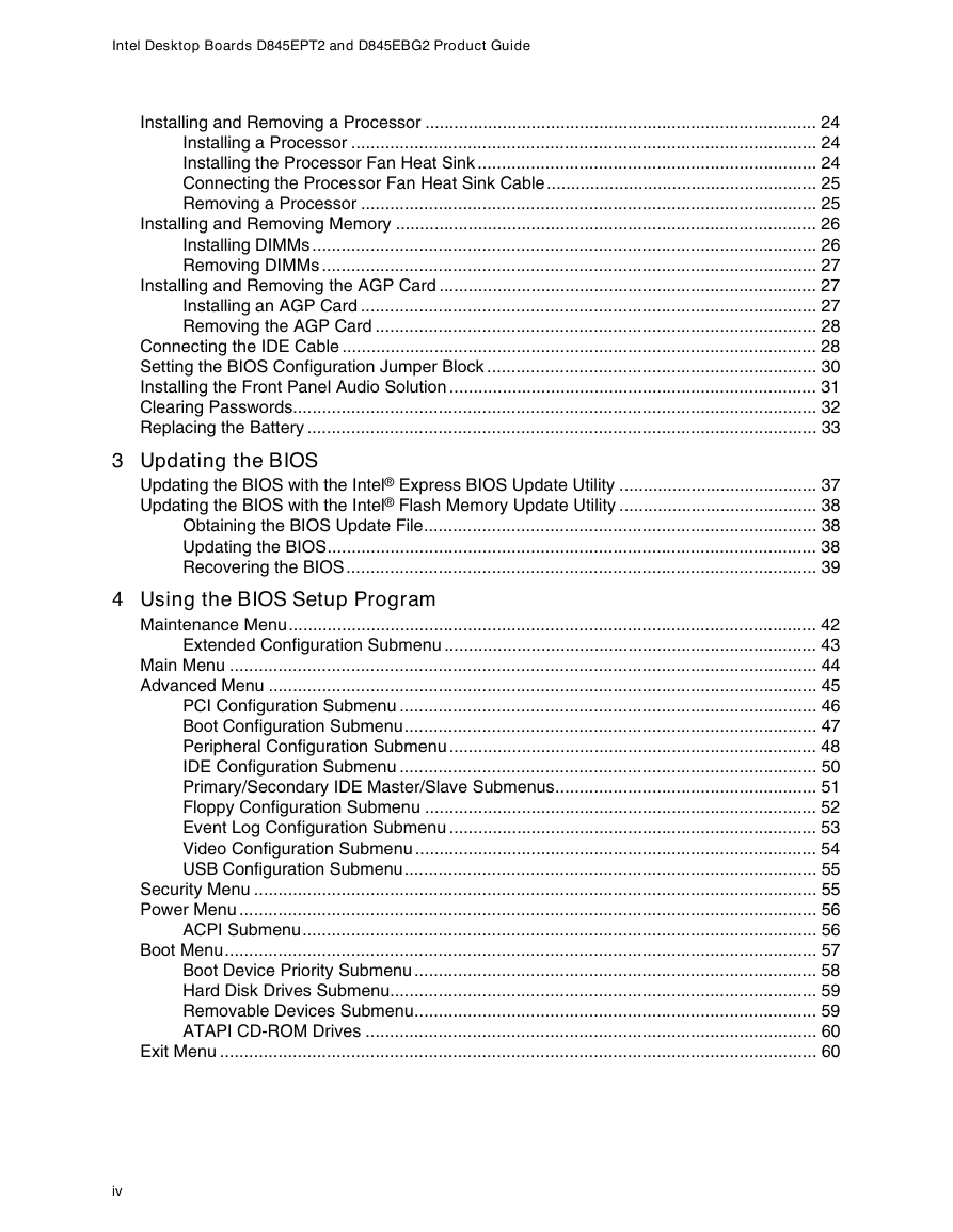
Contents 1 Desktop Board Features Desktop Board Components ................................................................................................ 9 Processor ........................................................................................................................... 11 Main Memory ..................................................................................................................... 12 Intel® 845E Chipset ............................................................................................................ 12 Intel® 82845E Memory Controller Hub (MCH) ........................................................... 13 Intel® 82801DB I/O Controller Hub (ICH4)................................................................. 13 Firmware Hub (FWH)................................................................................................. 13 Input/Output (I/O) Controller............................................................................................... 13 Audio Subsystem ............................................................................................................... 14 LAN Subsystem (Optional) ................................................................................................. 14 LAN Subsystem Software.......................................................................................... 14 RJ-45 LAN Connector LEDs ...................................................................................... 14 Hi-Speed USB 2.0 Support................................................................................................. 15 Enhanced IDE Interface ..................................................................................................... 15 Expansion Slots.................................................................................................................. 16 Accelerated Graphics Port (AGP) .............................................................................. 16 Communication and Networking Riser (CNR) (Optional) ........................................... 16 BIOS .................................................................................................................................. 16 PCI Auto Configuration .............................................................................................. 16 IDE Auto Configuration .............................................................................................. 17 Security Passwords ................................................................................................... 17 Power Management Features ............................................................................................ 17 ACPI.......................................................................................................................... 17 Suspend to RAM (Instantly Available PC Technology) .............................................. 17 Hardware Management ...................................................................................................... 19 Power Connectors ..................................................................................................... 19 Fan Connectors ......................................................................................................... 19 Resume on Ring........................................................................................................ 19 Wake from USB......................................................................................................... 19 Wake from PS/2 Keyboard/Mouse............................................................................. 19 PME# Wakeup Support ............................................................................................. 19 Speaker.............................................................................................................................. 20 Battery................................................................................................................................ 20 Real-Time Clock................................................................................................................. 20 Installing and Replacing Desktop Board Components Before You Begin ............................................................................................................... 21 Installing the I/O Shield....................................................................................................... 22 Installing and Removing the Desktop Board....................................................................... 23 iii 2
Intel Desktop Boards D845EPT2 and D845EBG2 Product Guide Installing and Removing a Processor ................................................................................. 24 Installing a Processor ................................................................................................ 24 Installing the Processor Fan Heat Sink ...................................................................... 24 Connecting the Processor Fan Heat Sink Cable........................................................ 25 Removing a Processor .............................................................................................. 25 Installing and Removing Memory ....................................................................................... 26 Installing DIMMs ........................................................................................................ 26 Removing DIMMs ...................................................................................................... 27 Installing and Removing the AGP Card .............................................................................. 27 Installing an AGP Card .............................................................................................. 27 Removing the AGP Card ........................................................................................... 28 Connecting the IDE Cable .................................................................................................. 28 Setting the BIOS Configuration Jumper Block .................................................................... 30 Installing the Front Panel Audio Solution ............................................................................ 31 Clearing Passwords............................................................................................................ 32 Replacing the Battery ......................................................................................................... 33 3 Updating the BIOS Updating the BIOS with the Intel® Express BIOS Update Utility ......................................... 37 Updating the BIOS with the Intel® Flash Memory Update Utility ......................................... 38 Obtaining the BIOS Update File................................................................................. 38 Updating the BIOS..................................................................................................... 38 Recovering the BIOS................................................................................................. 39 4 Using the BIOS Setup Program Maintenance Menu............................................................................................................. 42 Extended Configuration Submenu ............................................................................. 43 Main Menu ......................................................................................................................... 44 Advanced Menu ................................................................................................................. 45 PCI Configuration Submenu ...................................................................................... 46 Boot Configuration Submenu..................................................................................... 47 Peripheral Configuration Submenu ............................................................................ 48 IDE Configuration Submenu ...................................................................................... 50 Primary/Secondary IDE Master/Slave Submenus...................................................... 51 Floppy Configuration Submenu ................................................................................. 52 Event Log Configuration Submenu ............................................................................ 53 Video Configuration Submenu ................................................................................... 54 USB Configuration Submenu..................................................................................... 55 Security Menu .................................................................................................................... 55 Power Menu ....................................................................................................................... 56 ACPI Submenu.......................................................................................................... 56 Boot Menu.......................................................................................................................... 57 Boot Device Priority Submenu ................................................................................... 58 Hard Disk Drives Submenu........................................................................................ 59 Removable Devices Submenu................................................................................... 59 ATAPI CD-ROM Drives ............................................................................................. 60 Exit Menu ........................................................................................................................... 60 iv
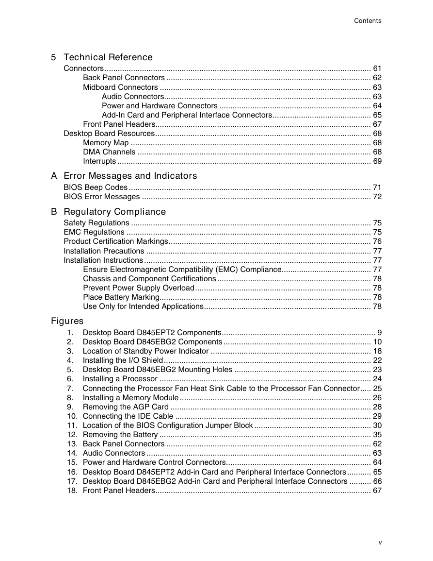
Contents 5 Technical Reference Connectors......................................................................................................................... 61 Back Panel Connectors ............................................................................................. 62 Midboard Connectors ................................................................................................ 63 Audio Connectors.............................................................................................. 63 Power and Hardware Connectors ..................................................................... 64 Add-In Card and Peripheral Interface Connectors............................................. 65 Front Panel Headers.................................................................................................. 67 Desktop Board Resources.................................................................................................. 68 Memory Map ............................................................................................................. 68 DMA Channels .......................................................................................................... 68 Interrupts ................................................................................................................... 69 A Error Messages and Indicators BIOS Beep Codes .............................................................................................................. 71 BIOS Error Messages ........................................................................................................ 72 B Regulatory Compliance Safety Regulations ............................................................................................................. 75 EMC Regulations ............................................................................................................... 75 Product Certification Markings............................................................................................ 76 Installation Precautions ...................................................................................................... 77 Installation Instructions....................................................................................................... 77 Ensure Electromagnetic Compatibility (EMC) Compliance......................................... 77 Chassis and Component Certifications ...................................................................... 78 Prevent Power Supply Overload................................................................................ 78 Place Battery Marking................................................................................................ 78 Use Only for Intended Applications............................................................................ 78 Figures 1. Desktop Board D845EPT2 Components...................................................................... 9 2. Desktop Board D845EBG2 Components ................................................................... 10 3. Location of Standby Power Indicator ......................................................................... 18 Installing the I/O Shield.............................................................................................. 22 4. 5. Desktop Board D845EBG2 Mounting Holes .............................................................. 23 Installing a Processor ................................................................................................ 24 6. 7. Connecting the Processor Fan Heat Sink Cable to the Processor Fan Connector..... 25 Installing a Memory Module ....................................................................................... 26 8. 9. Removing the AGP Card ........................................................................................... 28 10. Connecting the IDE Cable ......................................................................................... 29 11. Location of the BIOS Configuration Jumper Block ..................................................... 30 12. Removing the Battery ................................................................................................ 35 13. Back Panel Connectors ............................................................................................. 62 14. Audio Connectors ...................................................................................................... 63 15. Power and Hardware Control Connectors.................................................................. 64 16. Desktop Board D845EPT2 Add-in Card and Peripheral Interface Connectors ........... 65 17. Desktop Board D845EBG2 Add-in Card and Peripheral Interface Connectors .......... 66 18. Front Panel Headers.................................................................................................. 67 v
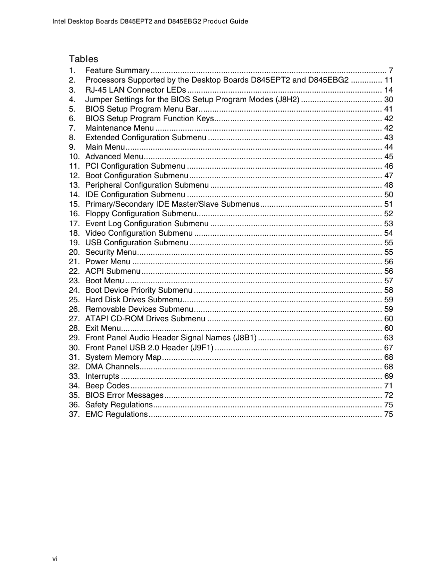
Intel Desktop Boards D845EPT2 and D845EBG2 Product Guide Tables 1. Feature Summary........................................................................................................ 7 2. Processors Supported by the Desktop Boards D845EPT2 and D845EBG2 .............. 11 3. RJ-45 LAN Connector LEDs ...................................................................................... 14 4. Jumper Settings for the BIOS Setup Program Modes (J8H2) .................................... 30 5. BIOS Setup Program Menu Bar................................................................................. 41 6. BIOS Setup Program Function Keys.......................................................................... 42 7. Maintenance Menu .................................................................................................... 42 8. Extended Configuration Submenu ............................................................................. 43 9. Main Menu................................................................................................................. 44 10. Advanced Menu......................................................................................................... 45 11. PCI Configuration Submenu ...................................................................................... 46 12. Boot Configuration Submenu..................................................................................... 47 13. Peripheral Configuration Submenu ............................................................................ 48 14. IDE Configuration Submenu ...................................................................................... 50 15. Primary/Secondary IDE Master/Slave Submenus...................................................... 51 16. Floppy Configuration Submenu.................................................................................. 52 17. Event Log Configuration Submenu ............................................................................ 53 18. Video Configuration Submenu ................................................................................... 54 19. USB Configuration Submenu..................................................................................... 55 20. Security Menu............................................................................................................ 55 21. Power Menu .............................................................................................................. 56 22. ACPI Submenu.......................................................................................................... 56 23. Boot Menu ................................................................................................................. 57 24. Boot Device Priority Submenu ................................................................................... 58 25. Hard Disk Drives Submenu........................................................................................ 59 26. Removable Devices Submenu................................................................................... 59 27. ATAPI CD-ROM Drives Submenu ............................................................................. 60 28. Exit Menu................................................................................................................... 60 29. Front Panel Audio Header Signal Names (J8B1) ....................................................... 63 30. Front Panel USB 2.0 Header (J9F1) .......................................................................... 67 31. System Memory Map................................................................................................. 68 32. DMA Channels........................................................................................................... 68 33. Interrupts ................................................................................................................... 69 34. Beep Codes............................................................................................................... 71 35. BIOS Error Messages................................................................................................ 72 36. Safety Regulations..................................................................................................... 75 37. EMC Regulations....................................................................................................... 75 vi
1 Desktop Board Features ✏ NOTE The Intel® Desktop Board D845EPT2 layout was used for illustrations unless otherwise noted. Table 1 describes the major features of the Desktop Boards D845EPT2 and D845EBG2. Table 1. Form Factors Feature Summary Processor Memory Chipset I/O Control Graphics Audio • microATX at 8.2 inches by 9.6 inches (Desktop Board D845EPT2) • ATX at 8.2 inches by 12.0 inches (Desktop Board D845EBG2) Support for a single Intel® Pentium® 4 processor with 533/400 MHz front side bus (FSB) frequency in an mPGA478 socket • Two 184-pin, 2.5 V SDRAM Dual Inline Memory Module (DIMM) sockets • 266/200 MHz DDR SDRAM interface • Designed to support up to 2 GB of system memory NOTE: The Desktop Boards D845EPT2 and D845EBG2 have been designed to support DIMMs based on 512 Mbit technology up to 2 GB, but this technology has not been validated on these Intel® desktop boards. For more information about the latest list of tested memory, refer to the Intel World Wide Web site at: http://support.intel.com/support/motherboards/desktop/ • Intel® 845E chipset consisting of: • Intel® 82845E Memory Controller Hub (MCH) with Accelerated Hub Architecture (AHA) bus • Intel® 82801DB I/O Controller Hub (ICH4) with support for up to six Hi-Speed Universal Serial Bus 2.0 (USB 2.0) ports • 4 Mbit Firmware Hub (FWH) SMSC LPC47M102S low pin count (LPC) interface I/O controller AGP connector supporting 1.5 V 4X and 2X AGP cards • Intel 845E chipset (AC ’97) • Analog Devices Inc. audio codec featuring SoundMAX† with SPX† software support LAN (optional) Peripheral Interfaces Intel® 82562ET 10/100 Mbit/sec Platform LAN Connect (PLC) device and RJ-45 connector • Up to six USB 2.0 ports — Four ports routed to the back panel — Two ports routed to the USB front panel header • Two IDE interfaces with Ultra DMA-33 and ATA-66/100 support • One floppy drive interface • One parallel port • Two serial ports (one via a board header) • PS/2† keyboard and mouse ports continued 7
Intel Desktop Boards D845EPT2 and D845EBG2 Product Guide Table 1. Feature Summary (continued) Expansion Capabilities • Desktop Board D845EPT2: — Three PCI bus add-in card connectors — One AGP connector — One optional CNR connector (slot shared with PCI bus connector 3) • Desktop Board D845EBG2: — Six PCI bus add-in card connectors — One AGP connector — One optional CNR connector (slot shared with PCI bus connector 6) BIOS Power Management • Intel/AMI BIOS • Intel® Rapid BIOS Boot • Intel® Express BIOS Update • SMBIOS support • Support for Advanced Configuration and Power Interface (ACPI) • Support for Suspend to RAM (Instantly Available PC) Hardware Management Hardware monitor with: • Two fan sensing inputs used to monitor fan activity • Remote diode temperature sensing • Voltage sensing to detect out of range values • WfM 2.0 compliant ✏ NOTE For information about Intel Desktop Boards D845EPT2 and D845EBG2, including the Technical Product Specification (TPS), BIOS updates, and device drivers, go to the Intel customer support World Wide Web site: http://support.intel.com/support/motherboards/desktop/ 8
分享到:
收藏