4-115-585-11 (2)
Data Projector
Operating Instructions
Before operating the unit, please read this manual
thoroughly and retain it for future reference.
SRX-T110
SRX-T105
© 2008 Sony Corporation
�
guarantee matters please refer to the addresses given in
separate service or guarantee documents.
This apparatus shall not be used in the residential area.
For kundene i Norge
Dette utstyret kan kobles til et IT-strømfordelingssystem.
For the State of California, USA only
Perchlorate Material - special handling may apply, See
www.dtsc.ca.gov/hazardouswaste/perchlorate
Perchlorate Material : Lithium battery contains
perchlorate.
For the customers in Taiwan only
Owner’s Record
The model and serial numbers are located at the side.
Record these numbers in the spaces provided below.
Refer to these numbers whenever you call upon your Sony
dealer regarding this product.
Model No.____________________
Serial No.____________________
WARNING
To reduce the risk of fire or electric shock, do not
expose this apparatus to rain or moisture.
To avoid electrical shock, do not open the
cabinet. Refer servicing to qualified personnel
only.
WARNING
THIS APPARATUS MUST BE EARTHED.
For the customers in the U.S.A.
This equipment has been tested and found to comply with
the limits for a Class A digital device, pursuant to Part 15
of the FCC Rules. These limits are designed to provide
reasonable protection against harmful interference when
the equipment is operated in a commercial environment.
This equipment generates, uses, and can radiate radio
frequency energy and, if not installed and used in
accordance with the instruction manual, may cause
harmful interference to radio communications. Operation
of this equipment in a residential area is likely to cause
harmful interference in which case the user will be
required to correct the interference at his own expense.
You are cautioned that any changes or modifications not
expressly approved in this manual could void your
authority to operate this equipment.
All interface cables used to connect peripherals must be
shielded in order to comply with the limits for a digital
device pursuant to Subpart B of Part 15 of FCC Rules.
For the customers in Europe, Australia and New
Zealand
WARNING
This is a Class A product. In a domestic environment, this
product may cause radio interference in which case the
user may be required to take adequate measures.
For the customers in Europe
The manufacturer of this product is Sony Corporation, 1-
7-1 Konan, Minato-ku, Tokyo, Japan.
The Authorized Representative for EMC and product
safety is Sony Deutschland GmbH, Hedelfinger Strasse
61, 70327 Stuttgart, Germany. For any service or
2
�
Table of Contents
Chapter 1 Overview
Precautions ......................................................................................5
Features............................................................................................7
Location and Function of Controls ................................................8
Projector Unit ........................................................................................ 8
Control Function Menu Window .......................................................... 9
Remote Commander............................................................................ 11
Chapter 2 Preparations
Precautions on Installation...........................................................13
Unsuitable Installation......................................................................... 13
Unsuitable Conditions ......................................................................... 14
Installation......................................................................................14
Using the Carrying Handles ................................................................ 14
Using the Adjusters ............................................................................. 14
Installing the Projector ........................................................................ 15
Installing the SRX Controller in a Computer for Controlling
the Projector............................................................................15
System Requirements .......................................................................... 15
Installing the SRX Controller.............................................................. 15
Connecting a Computer for Controlling the Projector...............17
Connecting the Computer via the Ethernet ......................................... 17
Connecting the Computer via the RS-232C ........................................ 18
Starting the SRX Controller ..........................................................18
Starting the SRX Controller ................................................................ 18
Changing the Connection Mode.......................................................... 19
Connecting the Projector..............................................................20
Connecting a Computer Equipped with a DVI-D Connector.............. 20
Connecting with a Computer Equipped with an Analog RGB
Connector................................................................................... 20
Connecting with HD-SDI Equipment ................................................. 21
Connecting with Component/Video GBR Equipment ........................ 21
Chapter 3 Projecting
Table of Contents 3
�
Projecting the Picture ...................................................................22
Using the Remote Commander ........................................................... 22
Using the Computer for Controlling the Projector.............................. 23
Projecting a 4K Signal in Single-screen Mode ................................... 25
Chapter 4 Adjustments and Settings Using the SRX Controller
Displaying the Control Function Menu Window .........................26
PICTURE CONTROL Window .......................................................27
Board ................................................................................................... 27
Input Source ........................................................................................ 27
Signal Info (Information) .................................................................... 28
Signal Adjust ....................................................................................... 28
COLOR/FRAME Window ...............................................................29
Board ................................................................................................... 29
Color.................................................................................................... 29
Frame Adjust ....................................................................................... 30
INSTALLATION Window................................................................30
LENS CONTROL ............................................................................... 30
ELECTRIC V SHIFT FUNCTION..................................................... 30
SIRCS.................................................................................................. 31
IMAGE FLIP....................................................................................... 31
PROGRESSIVE DISPLAY MODE ................................................... 31
SQUEEZE ........................................................................................... 31
LAMP POWER................................................................................... 31
LAMP SELECT .................................................................................. 31
TEST PATTERN ................................................................................ 32
Input Signals And Adjustable/Setting Items ...............................33
Chapter 5 Others
Lamp Life........................................................................................34
Maintenance ...................................................................................34
Troubleshooting ............................................................................35
Error Messages..............................................................................36
Specifications ................................................................................38
Index ...............................................................................................42
4 Table of Contents
�
C
h
a
p
t
e
r
1
O
v
e
r
v
e
w
i
Overview
Chapter
1
Precautions
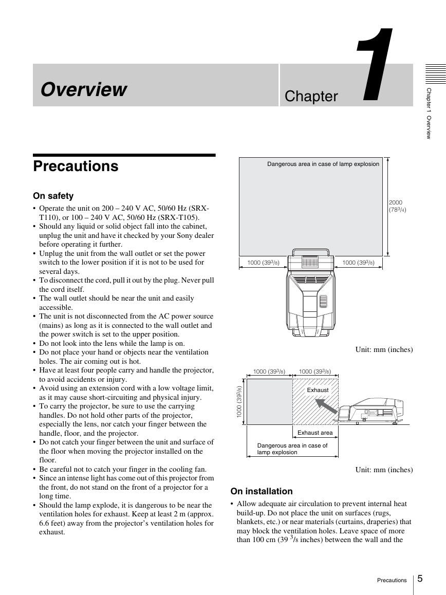
Dangerous area in case of lamp explosion
On safety
Operate the unit on 200 – 240 V AC, 50/60 Hz (SRX-
T110), or 100 – 240 V AC, 50/60 Hz (SRX-T105).
Should any liquid or solid object fall into the cabinet,
unplug the unit and have it checked by your Sony dealer
before operating it further.
Unplug the unit from the wall outlet or set the power
switch to the lower position if it is not to be used for
several days.
To disconnect the cord, pull it out by the plug. Never pull
the cord itself.
The wall outlet should be near the unit and easily
accessible.
The unit is not disconnected from the AC power source
(mains) as long as it is connected to the wall outlet and
the power switch is set to the upper position.
Do not look into the lens while the lamp is on.
Do not place your hand or objects near the ventilation
holes. The air coming out is hot.
2000
(783/4)
1000 (393/8)
1000 (393/8)
Unit: mm (inches)
Have at least four people carry and handle the projector,
1000 (393/8)
1000 (393/8)
to avoid accidents or injury.
Avoid using an extension cord with a low voltage limit,
as it may cause short-circuiting and physical injury.
To carry the projector, be sure to use the carrying
handles. Do not hold other parts of the projector,
especially the lens, nor catch your finger between the
handle, floor, and the projector.
Do not catch your finger between the unit and surface of
the floor when moving the projector installed on the
floor.
Be careful not to catch your finger in the cooling fan.
Since an intense light has come out of this projector from
the front, do not stand on the front of a projector for a
long time.
Should the lamp explode, it is dangerous to be near the
ventilation holes for exhaust. Keep at least 2 m (approx.
6.6 feet) away from the projector’s ventilation holes for
exhaust.
Exhaust
)
8
/
3
9
3
(
0
0
0
1
Exhaust area
Dangerous area in case of
lamp explosion
Unit: mm (inches)
On installation
Allow adequate air circulation to prevent internal heat
build-up. Do not place the unit on surfaces (rugs,
blankets, etc.) or near materials (curtains, draperies) that
may block the ventilation holes. Leave space of more
than 100 cm (39 3/8 inches) between the wall and the
Precautions
5
�
C
h
a
p
t
e
r
1
O
v
e
r
v
e
w
i
For maximum protection, repack your unit as it was
originally packed at the factory.
On “stuck” pixels on a LCD screen
The LCD panel fitted to this unit is manufactured with high
precision technology. Thus a very small proportion of
pixels may be “stuck”, either always off (black), always on
(red, green, or blue), or flashing. In addition, over a long
period of use, because of the physical characteristics of the
liquid crystal display, such “stuck” pixels may appear
spontaneously. These problems are not a malfunction.
On prohibiting continuous lighting
Continuously lighting the Xenon lamp for 24 hours will
reduce approximately half of its lamp life. Be sure to off
the lamp for an hour or more after continuously lighting for
24 hours.
To light the lamp continuously for 24 hours, it is
recommended to use the lamps alternately. To use the
lamps alternately, select “User-Defined” in “Single” (page
31) under “LAMP SELECT” in the INSTALLATION
window and set the time.
projector. Be aware that room heat rises to the ceiling;
check that the temperature near the installation location
is not excessive.
Install the projector on the floor or hang it from the
ceiling. Any other installation causes a malfunction such
as color irregularity or a shorten lamp life.
Do not install the unit in a location near heat sources
such as radiators or air ducts, or in a place subject to
direct sunlight, excessive dust or humidity, mechanical
vibration or shock.
To avoid moisture condensation, do not install the unit in
a location where the temperature may rise rapidly.
On illumination
To obtain the best picture, the front of the screen should
not be exposed to direct lighting or sunlight.
Ceiling-mounted spot lighting is recommended. Use a
cover over fluorescent lamps to avoid lowering the
contrast ratio.
Cover any windows that face the screen with opaque
draperies.
It is desirable to install the projector in a room where
floor and walls are not of light-reflecting material. If the
floor and walls are of reflecting material, it is
recommended that the carpet and wall paper be changed
to a dark color.
On preventing internal heat build-up
After turning off the power, the cooling fan runs for about
10 minutes while the STATUS LAMP indicator flashes
green.
Caution
The projector is equipped with ventilation holes (intake) at
the front, upper side and right side, and ventilation holes
(exhaust) at the rear and upper side.
Do not block or place anything near these holes, or internal
heat build-up may occur, causing picture degradation or
damage to the projector.
On cleaning
To keep the cabinet looking new, periodically clean it
with a soft cloth. Stubborn stains may be removed with
a cloth lightly dampened with a mild detergent solution.
Never use strong solvents, such as thinner, benzene, or
abrasive cleansers, since these will damage the cabinet.
Avoid touching the lens. To remove dust on the lens, use
a soft dry cloth. Do not use a damp cloth, detergent
solution, or thinner.
On repacking
Save the original shipping carton and packing material;
they will come in handy if you ever have to ship your unit.
6 Precautions
�
C
h
a
p
t
e
r
1
O
v
e
r
v
e
w
i
Flexible and Reliable System
Dual lamp system
The projector adopts a dual lamp system for versatility of
use. You can select dual-lamp or single-lamp mode, and
can reduce each lamp’s power output. These modes allow
you to save power and increase lamp life.
Also, if one bulb burns out, the other keeps projecting
images.
Versatile Setup
Various signal input
The projector is equipped with an RS232C connector and
ETHERNET connector for communication. For signal
inputs, the projector has four slots to which the optional
analog input boards, HD-SDI input boards and DVI-D
interface boards can be attached according to your
requirement.
Optional lens
Optional zoom lenses are available depending on the
projection distance you are setting up. The lens shift
function of this projector enables easy setup.
When the optional zoom lens equipped with zoom/focus
memory function is installed, you can register the zoom
and focus settings adjusted to fit the desired screen size.
Registration of the settings adjusted for screen sizes of
aspect ratio of 4:3 and 16:9 allows you to switch between
them easily with the buttons in the window of the SRX
Controller.
Features
High Brightness, High Picture Quality
High brightness
The SRX-T110 uses two 2 kW Xenon lamps as a light
source, and the SRX-T105 uses two 1 kW Xenon lamps.
These compact-size Xenon lamps provide high brightness
of 11,000 lumens for the SRX-T110 and 5,500 lumens for
the SRX-T105, assuring excellent uniformity on the entire
screen.
High resolution
Sony’s new, unique three SXRD™ (Silicon X-tal
Reflective Display) panels with about 8,850,000 pixels
realizes a high-resolution of 4096 × 2160 dots. The
resolution corresponds to four times that of an HDTV
image.
Multi-screen mode
The high resolution of the projector enables single-, dual-
and quad-mode projection in which full HD images can be
displayed even in each of two or four divided screens.
Images from different input sources can be displayed in
these divided screens simultaneously.
High contrast ratio
The combination of the SXRD imaging devices and 3PBS
optical devices offers a high contrast ratio of 2500:1.
Gamma correction circuit
You can select a gamma value from 1.80 to 2.59 in 0.01
steps according to the signal input. (The values of 2.2 and
2.6 are fixed.) This allows projection of an image with
optimum brightness. (Only three types of gamma
correction circuit, 1.8, 2.2 and 2.6, may be selectable
according to the optional input board.)
Color space feature
The projector supports four standards of color tonal
reproduction range, sRGB(ITU-R BT.709), DCDM,
Adobe RGB and CIE XYZ, allowing you to obtain an
image with precise color reproduction according to the
input sources.
Squeeze function
A squeezed signal with a 4:3 aspect ratio is stretched
horizontally to fit a 16:9 screen, and a signal with a 16:9
aspect ratio is stretched horizontally to fit a 2.39:1 screen.
This function is available only for projection in single-
screen mode and may not work depending on the signal
type input.
Features
7
�
Location and Function of
Controls
Left Side/Rear
1
2
C
h
a
p
Projector Unit
t
e
r
1
O
v
e
r
v
e
w
i
Front/Top
1 2
3
54
6 7 8
a Remote control detector (front)
b Upper side ventilation holes (intake)
3
4
5 6
7 8 0
9
qa
qs
a Cooling unit
A cooling fan and the two lamp houses (these are not
supplied) are installed here.
For installation and replacement of a lamp house, consult
your Sony dealer.
c Upper side ventilation holes (exhaust)
b Upper/rear side ventilation holes (exhaust)
d Adjusters
Use to keep this unit level if it is installed on an uneven
surface.
e Lens cover
f Lens mount part
When attaching the optional lens, consult your Sony
dealer.
g Carrying handle
Use to carry the projector. There is another handle on the
rear side.
h Front/right side ventilation holes (intake)
c Remote control detector (rear)
d Power switch
Set the switch to the upper position to turn on the main
power of the projector. To turn it off, set the switch to the
lower position.
e AC IN terminal board
Connect the AC power cord with three wires (not
supplied).
For connection of the AC power cord, contact your Sony
dealer.
f STATUS MESSAGE window
Displays an error message. If the message is displayed,
contact your Sony dealer.
g STATUS LAMP indicator
Lights red when the projector is in standby mode. When
the power is turned on, it lights green. The indicator flashes
for about 10 minutes after the power is turned off by
clicking “POWER STANDBY 1” in the Control Function
Menu window or by pressing the 1 button on the Remote
8 Location and Function of Controls
�


 2023年江西萍乡中考道德与法治真题及答案.doc
 2012年重庆南川中考生物真题及答案.doc
 2013年江西师范大学地理学综合及文艺理论基础考研真题.doc
 2020年四川甘孜小升初语文真题及答案I卷.doc
 2020年注册岩土工程师专业基础考试真题及答案.doc
 2023-2024学年福建省厦门市九年级上学期数学月考试题及答案.doc
 2021-2022学年辽宁省沈阳市大东区九年级上学期语文期末试题及答案.doc
 2022-2023学年北京东城区初三第一学期物理期末试卷及答案.doc
 2018上半年江西教师资格初中地理学科知识与教学能力真题及答案.doc
 2012年河北国家公务员申论考试真题及答案-省级.doc
 2020-2021学年江苏省扬州市江都区邵樊片九年级上学期数学第一次质量检测试题及答案.doc
 2022下半年黑龙江教师资格证中学综合素质真题及答案.doc