logo资料库

IEC 61980-2.pdf

第1页 / 共88页
第2页 / 共88页
第3页 / 共88页
第4页 / 共88页
第5页 / 共88页
第6页 / 共88页
第7页 / 共88页
第8页 / 共88页
资料共88页,剩余部分请下载后查看
IEC-TC69-WG7-N23-020-69_529_DTS
INTERNATIONAL ELECTROTECHNICAL COMMISSION
IEC 61980: Electric vehicle wireless power transfer (WPT) systems –
Part 2: specific requirements for communication between electric road vehicle (EV) and infrastructure with respect to wireless power transfer (WPT) systems
69_529e_DTS
FOREWORD
INTRODUCTION
1 Scope
2 Normative references
3 Terms and definitions
3.201
3.202
4 Abbreviations
5 Communication of WPT systems
5.1 General
5.2 System architecture
5.3 General system requirements
5.3.1 General
5.3.2 Interoperability requirements
5.3.3 System configuration
5.3.4 Communication security
5.3.5 Timing
6 Power transfer process with respect to communication
6.1 General
6.2 Overview of Operation process Activities
6.3 Activities
6.3.1 Communication setup and service selection
6.3.2  Reject WPT Session
6.3.3 Fine positioning
6.3.4 Pairing
6.3.5 Final compatibility check
6.3.6 Initial alignment check
6.3.7 Start power transfer
6.3.8 Time scheduled power transfer (informative)
6.3.8.1 General
6.3.8.2 Power saver wake up
6.3.8.3 Sleep/power saver
6.3.9 Perform power transfer
6.3.10 Stop power transfer
6.3.11  WPT session
6.3.12 EV leaves WPT spot
6.3.13 Safety monitoring & diagnostics
6.3.13.1 General
6.3.13.2  Continuous alignment check
6.3.13.3 Communication link monitoring
6.3.14 Terminate communication
6.3.15 Terminate safety monitoring & diagnostics
6.3.16 Wake up after power outage
7 Control process states
7.1 Supply device state definitions
7.1.1 Supply device state diagram
7.1.2 Stand by (WPT_S_SB)
7.1.3 Service initiated (WPT_S_SI)
7.1.4 WPT Session rejected
7.1.5 Awaiting alignment (WPT_S_AA)
7.1.6 Idle (WPT_S_IDLE)
7.1.7 Power transfer (WPT_S_PT)
7.1.8 Service terminated occupied (WPT_S_STO)
7.1.9 Out of service (WPT_S_OOS)
7.1.10 Sleep Mode WPT_S_SLP
7.2 Supply device state transitions
7.3 EV state definitions
7.3.1 EV state diagram
7.3.2 Stand by (WPT_V_SB)
7.3.3 Service initiated (WPT_V_SI)
7.3.4 Awaiting alignment (WPT_V_AA)
7.3.5 Idle (WPT_V_IDLE)
7.3.6 Power transfer active (WPT_V_PT)
7.3.7 Off (WPT_V_OFF)
7.4 EV state transitions
7.5 Exception handling
7.5.1 General
7.5.2 Supply device exception handling (WPT_S_ERR)
7.5.3 EV exception handling (WPT_V_ERR)
7.5.4 Exception descriptions
8 Communication parameter for WPT systems
8.1 General
8.2 General Parameters
8.3 Communication Setup
8.4 Service Selection
8.5 Fine Positioning
8.5.1 General
8.5.2 Starting fine positioning
8.5.3 Fine positioning data exchange
8.5.4 Terminating Fine Positioning
8.6 Pairing
8.6.1 General
8.6.2 Start Pairing
8.7 Initial alignment check
8.7.1 General
8.7.2 Initial alignment check request/response
8.8 Start Power Transfer
8.8.1 General
8.8.2 Final compatibility check
8.9 Perform Power Transfer
8.10 Stop Power Transfer
8.11 Terminate Communication
8.12 Exception Handling
9 Message sequences of communication with WLN
9.1 General
9.2 Messages of communication for power transfer
9.3 Communication setup
9.4 Service Selection
9.5 Fine positioning
9.6 Pairing
9.7 Final compatibility check
9.8 Initial alignment check
9.9 Start power transfer
9.10 Perform power transfer
9.11 Stop power transfer
9.12 Terminate communication
Annex A (informative) Use cases
A.1 General
A.2 Use case descriptions
A.2.1 UC Select supply device
A.2.2 UC Service Selection
A.2.3 UC Fine positioning
A.2.4 UC Start power transfer
A.2.5 UC Perform power transfer
A.2.6 UC Safety monitoring and diagnostics
A.2.7 UC Stop power transfer
A.2.8 UC Power saver mode (optional)
Annex B (informative) Physical definition of links and signals
B.1 System architecture
B.2 WLN
B.3 SR Signal
B.4 LF Signal (EV to supply device)
B.5 Magnetic Vector (EV to supply device)
B.6 LPE
Annex C (informative) Usage of Supplemental Signals
C.1 Fine positioning
C.1.1 Manual
C.1.2 Low power excitation (LPE)
C.1.3 LF Signal
C.1.4 Magnetic Vector
C.2 Pairing
C.2.1 Low power excitation (LPE)
C.2.2 SR Signal
C.2.2.1 Coding Pattern specification
C.2.3 LF Signal
C.2.4 Magnetic vector
C.3 Initial alignment check
C.3.1 Efficiency check
C.3.2 RSSI Method
C.3.3 Secondary voltage check
C.3.4 Coupling check
C.4 Continuous alignment check
C.4.1 Efficiency Check
C.4.2 SR Signal
C.4.3 Coupling check
C.5 Safety Signal
C.5.1 SR Signal
Bibliography
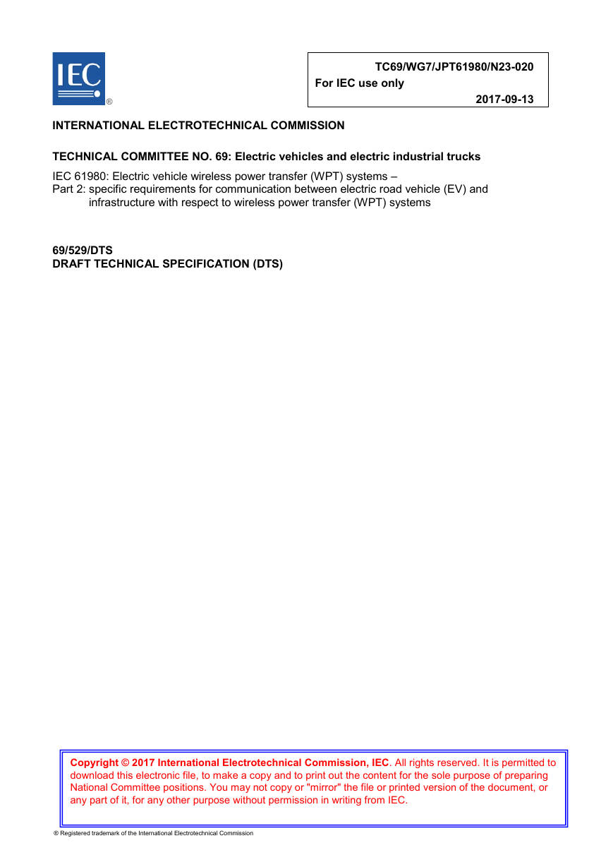
TC69/WG7/JPT61980/N23-020 For IEC use only 2017-09-13 ® INTERNATIONAL ELECTROTECHNICAL COMMISSION TECHNICAL COMMITTEE NO. 69: Electric vehicles and electric industrial trucks IEC 61980: Electric vehicle wireless power transfer (WPT) systems – Part 2: specific requirements for communication between electric road vehicle (EV) and infrastructure with respect to wireless power transfer (WPT) systems 69/529/DTS DRAFT TECHNICAL SPECIFICATION (DTS) Copyright © 2017 International Electrotechnical Commission, IEC. All rights reserved. It is permitted to download this electronic file, to make a copy and to print out the content for the sole purpose of preparing National Committee positions. You may not copy or "mirror" the file or printed version of the document, or any part of it, for any other purpose without permission in writing from IEC. ® Registered trademark of the International Electrotechnical Commission
DRAFT TECHNICAL SPECIFICATION (DTS) 69/529/DTS PROJECT NUMBER: IEC TS 61980-2 ED1 DATE OF CIRCULATION: 2017-09-08 SUPERSEDES DOCUMENTS: 69/480/CD,69/528/CC CLOSING DATE FOR VOTING: 2017-12-01 IEC TC 69 : ELECTRIC ROAD VEHICLES AND ELECTRIC INDUSTRIAL TRUCKS SECRETARIAT: Belgium SECRETARY: Mr Peter Van den Bossche OF INTEREST TO THE FOLLOWING COMMITTEES: TC 64,TC 77,CIS/B FUNCTIONS CONCERNED: EMC ENVIRONMENT QUALITY ASSURANCE SAFETY This document is still under study and subject to change. It should not be used for reference purposes. Recipients of this document are invited to submit, with their comments, notification of any relevant patent rights of which they are aware and to provide supporting documentation. TITLE: Electric vehicle wireless power transfer (WPT) systems - Part 2 specific requirements for communication between electric road vehicle (EV) and infrastructure with respect to wireless power transfer (WPT) systems NOTE FROM TC/SC OFFICERS: Copyright © 2017 International Electrotechnical Commission, IEC. All rights reserved. It is permitted to download this electronic file, to make a copy and to print out the content for the sole purpose of preparing National Committee positions. You may not copy or "mirror" the file or printed version of the document, or any part of it, for any other purpose without permission in writing from IEC.
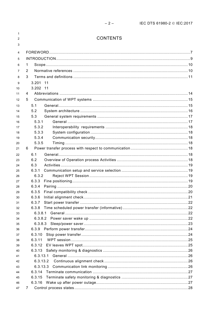
– 2 – IEC DTS 61980-2  IEC:2017 CONTENTS FOREWORD ........................................................................................................................... 7 INTRODUCTION ..................................................................................................................... 9 1 Scope ............................................................................................................................ 10 2 Normative references .................................................................................................... 10 3 Terms and definitions .................................................................................................... 11 6 6.3.2 3.201 11 3.202 11 5.1 5.2 5.3 4 Abbreviations ................................................................................................................ 14 5 Communication of WPT systems ................................................................................... 15 General ................................................................................................................. 15 System architecture .............................................................................................. 16 General system requirements ............................................................................... 17 General ......................................................................................................... 17 5.3.1 Interoperability requirements ........................................................................ 18 5.3.2 System configuration ..................................................................................... 18 5.3.3 Communication security ................................................................................. 18 5.3.4 5.3.5 Timing ........................................................................................................... 18 Power transfer process with respect to communication .................................................. 18 General ................................................................................................................. 18 6.1 Overview of Operation process Activities .............................................................. 18 6.2 6.3 Activities ............................................................................................................... 19 6.3.1 Communication setup and service selection .......................................................... 19 Reject WPT Session ...................................................................................... 19 6.3.3 Fine positioning ..................................................................................................... 19 6.3.4 Pairing .................................................................................................................. 20 6.3.5 Final compatibility check ....................................................................................... 20 6.3.6 Initial alignment check ........................................................................................... 21 6.3.7 Start power transfer .............................................................................................. 22 6.3.8 Time scheduled power transfer (informative) ......................................................... 22 6.3.8.1 General ........................................................................................................... 22 6.3.8.2 Power saver wake up ...................................................................................... 22 6.3.8.3 Sleep/power saver ........................................................................................... 23 6.3.9 Perform power transfer .......................................................................................... 24 6.3.10 Stop power transfer ............................................................................................. 24 6.3.11 WPT session ...................................................................................................... 25 6.3.12 EV leaves WPT spot............................................................................................ 25 6.3.13 Safety monitoring & diagnostics .......................................................................... 26 6.3.13.1 General ......................................................................................................... 26 6.3.13.2 Continuous alignment check ......................................................................... 26 6.3.13.3 Communication link monitoring ...................................................................... 26 6.3.14 Terminate communication ................................................................................... 27 6.3.15 Terminate safety monitoring & diagnostics .......................................................... 27 6.3.16 Wake up after power outage ................................................................................ 27 7 Control process states ................................................................................................... 28 1 2 3 4 5 6 7 8 9 10 11 12 13 14 15 16 17 18 19 20 21 22 23 24 25 26 27 28 29 30 31 32 33 34 35 36 37 38 39 40 41 42 43 44 45 46 47
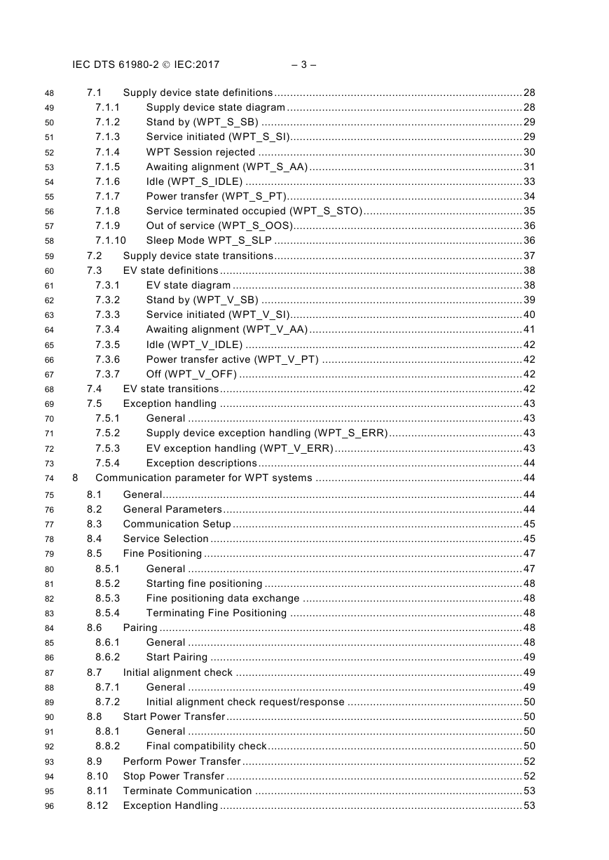
IEC DTS 61980-2  IEC:2017 – 3 – 7.1 7.4 7.5 7.2 7.3 7.5.1 7.5.2 7.5.3 7.5.4 7.3.1 7.3.2 7.3.3 7.3.4 7.3.5 7.3.6 7.3.7 7.1.1 7.1.2 7.1.3 7.1.4 7.1.5 7.1.6 7.1.7 7.1.8 7.1.9 7.1.10 Supply device state definitions .............................................................................. 28 Supply device state diagram .......................................................................... 28 Stand by (WPT_S_SB) .................................................................................. 29 Service initiated (WPT_S_SI)......................................................................... 29 WPT Session rejected ................................................................................... 30 Awaiting alignment (WPT_S_AA) ................................................................... 31 Idle (WPT_S_IDLE) ....................................................................................... 33 Power transfer (WPT_S_PT) .......................................................................... 34 Service terminated occupied (WPT_S_STO) .................................................. 35 Out of service (WPT_S_OOS)........................................................................ 36 Sleep Mode WPT_S_SLP .............................................................................. 36 Supply device state transitions .............................................................................. 37 EV state definitions ............................................................................................... 38 EV state diagram ........................................................................................... 38 Stand by (WPT_V_SB) .................................................................................. 39 Service initiated (WPT_V_SI)......................................................................... 40 Awaiting alignment (WPT_V_AA) ................................................................... 41 Idle (WPT_V_IDLE) ....................................................................................... 42 Power transfer active (WPT_V_PT) ............................................................... 42 Off (WPT_V_OFF) ......................................................................................... 42 EV state transitions ............................................................................................... 42 Exception handling ............................................................................................... 43 General ......................................................................................................... 43 Supply device exception handling (WPT_S_ERR) .......................................... 43 EV exception handling (WPT_V_ERR) ........................................................... 43 Exception descriptions ................................................................................... 44 8 Communication parameter for WPT systems ................................................................. 44 General ................................................................................................................. 44 General Parameters .............................................................................................. 44 Communication Setup ........................................................................................... 45 Service Selection .................................................................................................. 45 Fine Positioning .................................................................................................... 47 General ......................................................................................................... 47 Starting fine positioning ................................................................................. 48 Fine positioning data exchange ..................................................................... 48 Terminating Fine Positioning ......................................................................... 48 Pairing .................................................................................................................. 48 General ......................................................................................................... 48 Start Pairing .................................................................................................. 49 Initial alignment check .......................................................................................... 49 General ......................................................................................................... 49 Initial alignment check request/response ....................................................... 50 Start Power Transfer ............................................................................................. 50 General ......................................................................................................... 50 Final compatibility check ................................................................................ 50 8.9 Perform Power Transfer ........................................................................................ 52 8.10 Stop Power Transfer ............................................................................................. 52 8.11 Terminate Communication .................................................................................... 53 8.12 Exception Handling ............................................................................................... 53 8.5.1 8.5.2 8.5.3 8.5.4 8.1 8.2 8.3 8.4 8.5 8.6 8.6.1 8.6.2 8.7 8.8 8.7.1 8.7.2 8.8.1 8.8.2 48 49 50 51 52 53 54 55 56 57 58 59 60 61 62 63 64 65 66 67 68 69 70 71 72 73 74 75 76 77 78 79 80 81 82 83 84 85 86 87 88 89 90 91 92 93 94 95 96
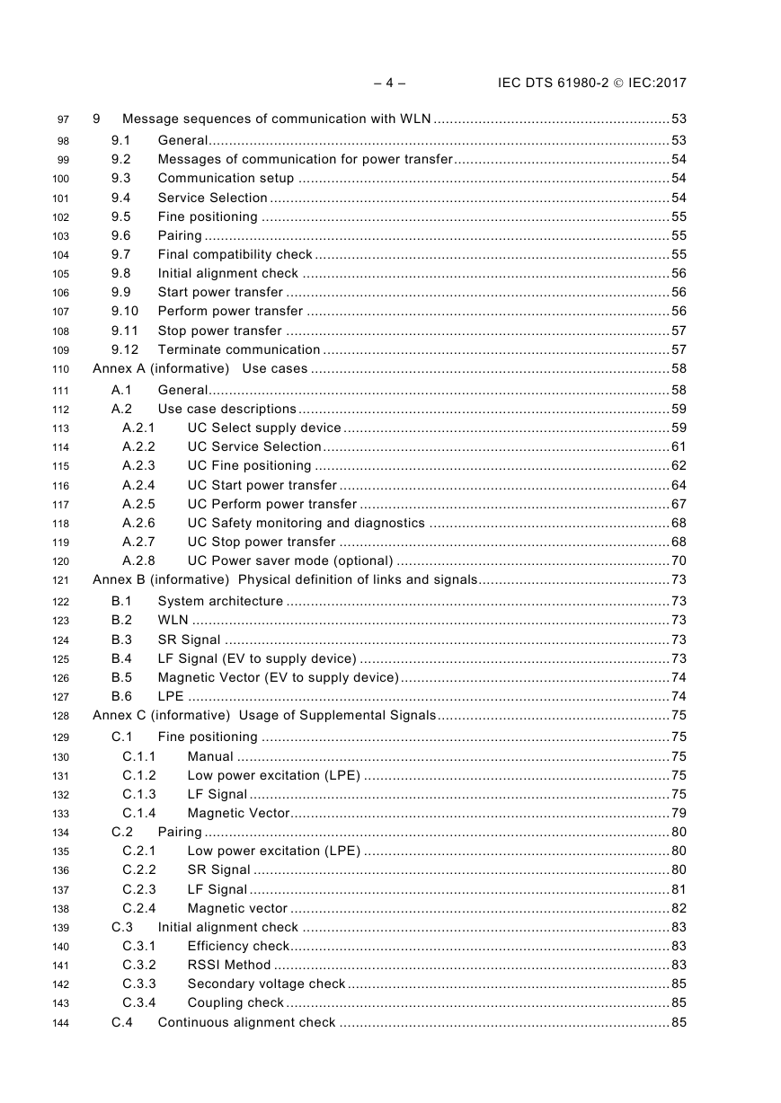
– 4 – IEC DTS 61980-2  IEC:2017 A.1 A.2 A.2.1 A.2.2 A.2.3 A.2.4 A.2.5 A.2.6 A.2.7 A.2.8 9 Message sequences of communication with WLN .......................................................... 53 General ................................................................................................................. 53 9.1 Messages of communication for power transfer ..................................................... 54 9.2 Communication setup ........................................................................................... 54 9.3 Service Selection .................................................................................................. 54 9.4 Fine positioning .................................................................................................... 55 9.5 Pairing .................................................................................................................. 55 9.6 Final compatibility check ....................................................................................... 55 9.7 Initial alignment check .......................................................................................... 56 9.8 Start power transfer .............................................................................................. 56 9.9 9.10 Perform power transfer ......................................................................................... 56 9.11 Stop power transfer .............................................................................................. 57 9.12 Terminate communication ..................................................................................... 57 Annex A (informative) Use cases ........................................................................................ 58 General ................................................................................................................. 58 Use case descriptions ........................................................................................... 59 UC Select supply device ................................................................................ 59 UC Service Selection ..................................................................................... 61 UC Fine positioning ....................................................................................... 62 UC Start power transfer ................................................................................. 64 UC Perform power transfer ............................................................................ 67 UC Safety monitoring and diagnostics ........................................................... 68 UC Stop power transfer ................................................................................. 68 UC Power saver mode (optional) ................................................................... 70 Annex B (informative) Physical definition of links and signals............................................... 73 B.1 System architecture .............................................................................................. 73 B.2 WLN ..................................................................................................................... 73 SR Signal ............................................................................................................. 73 B.3 LF Signal (EV to supply device) ............................................................................ 73 B.4 Magnetic Vector (EV to supply device) .................................................................. 74 B.5 B.6 LPE ...................................................................................................................... 74 Annex C (informative) Usage of Supplemental Signals ......................................................... 75 Fine positioning .................................................................................................... 75 Manual .......................................................................................................... 75 Low power excitation (LPE) ........................................................................... 75 LF Signal ....................................................................................................... 75 Magnetic Vector............................................................................................. 79 Pairing .................................................................................................................. 80 Low power excitation (LPE) ........................................................................... 80 SR Signal ...................................................................................................... 80 LF Signal ....................................................................................................... 81 Magnetic vector ............................................................................................. 82 Initial alignment check .......................................................................................... 83 Efficiency check ............................................................................................. 83 RSSI Method ................................................................................................. 83 Secondary voltage check ............................................................................... 85 Coupling check .............................................................................................. 85 Continuous alignment check ................................................................................. 85 C.1.1 C.1.2 C.1.3 C.1.4 C.1 C.2 C.3 C.2.1 C.2.2 C.2.3 C.2.4 C.3.1 C.3.2 C.3.3 C.3.4 C.4 97 98 99 100 101 102 103 104 105 106 107 108 109 110 111 112 113 114 115 116 117 118 119 120 121 122 123 124 125 126 127 128 129 130 131 132 133 134 135 136 137 138 139 140 141 142 143 144
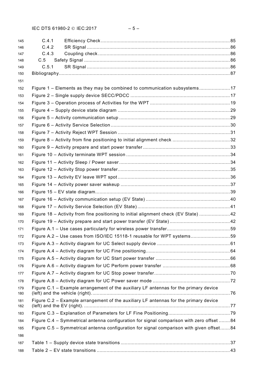
IEC DTS 61980-2  IEC:2017 – 5 – C.5 C.5.1 C.4.1 C.4.2 C.4.3 Efficiency Check ............................................................................................ 85 SR Signal ...................................................................................................... 86 Coupling check .............................................................................................. 86 Safety Signal ........................................................................................................ 86 SR Signal ...................................................................................................... 86 Bibliography .......................................................................................................................... 87 Figure 1 – Elements as they may be combined to communication subsystems ...................... 17 Figure 2 – Single supply device SECC/PDCC ....................................................................... 17 Figure 3 – Operation process of Activities for the WPT ......................................................... 19 Figure 4 – Supply device state diagram ................................................................................ 29 Figure 5 – Activity communication setup ............................................................................... 29 Figure 6 – Activity Service Selection ..................................................................................... 30 Figure 7 – Activity Reject WPT Session ................................................................................ 31 Figure 8 – Activity from fine positioning to initial alignment check ......................................... 32 Figure 9 – Activity prepare and start power transfer .............................................................. 33 Figure 10 – Activity terminate WPT session .......................................................................... 34 Figure 11 – Activity Sleep / Power saver ............................................................................... 34 Figure 12 – Activity Stop power transfer ................................................................................ 35 Figure 13 – Activity EV leave WPT spot ................................................................................ 36 Figure 14 – Activity power saver wakeup .............................................................................. 37 Figure 15 – EV state diagram................................................................................................ 39 Figure 16 – Activity communication setup (EV State) ............................................................ 40 Figure 17 – Activity Service Selection (EV State) .................................................................. 41 Figure 18 – Activity from fine positioning to initial alignment check (EV State) ...................... 42 Figure 19 – Activity prepare and start power transfer (EV State) ........................................... 42 Figure A.1 – Use cases particularly for wireless power transfer............................................. 59 Figure A.2 – Use cases from ISO/IEC 15118-1 reusable for WPT systems ............................ 59 Figure A.3 – Activity diagram for UC Select supply device .................................................... 61 Figure A.4 – Activity diagram for UC Fine positioning ............................................................ 64 Figure A.5 – Activity diagram for UC Start power transfer ..................................................... 66 Figure A.6 – Activity diagram for UC Perform power transfer ................................................ 68 Figure A.7 – Activity diagram for UC Stop power transfer ...................................................... 70 Figure A.8 – Activity diagram for UC Power saver mode ....................................................... 72 Figure C.1 – Example arrangement of the auxiliary LF antennas for the primary device (left) and the vehicle (right). .................................................................................................. 76 Figure C.2 – Example arrangement of the auxiliary LF antennas for the primary device (left) and the EV (right). ........................................................................................................ 77 Figure C.3 – Explanation of Parameters for LF Fine Positioning ............................................ 79 Figure C.4 – Symmetrical antenna configuration for signal comparison with zero offset ........ 84 Figure C.5 – Symmetrical antenna configuration for signal comparison with given offset ....... 84 Table 1 – Supply device state transitions .............................................................................. 37 Table 2 – EV state transitions ............................................................................................... 43 145 146 147 148 149 150 151 152 153 154 155 156 157 158 159 160 161 162 163 164 165 166 167 168 169 170 171 172 173 174 175 176 177 178 179 180 181 182 183 184 185 186 187 188
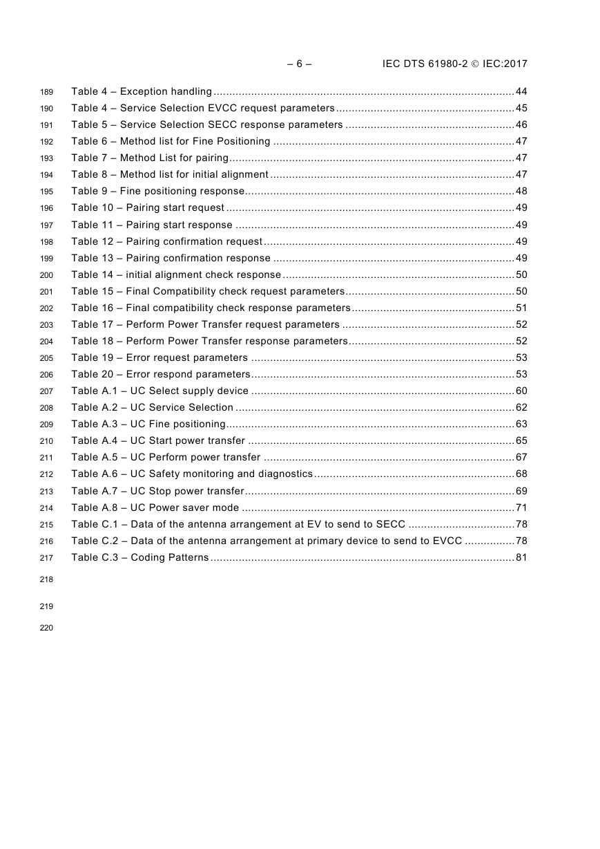
– 6 – IEC DTS 61980-2  IEC:2017 Table 4 – Exception handling ................................................................................................ 44 Table 4 – Service Selection EVCC request parameters ......................................................... 45 Table 5 – Service Selection SECC response parameters ...................................................... 46 Table 6 – Method list for Fine Positioning ............................................................................. 47 Table 7 – Method List for pairing ........................................................................................... 47 Table 8 – Method list for initial alignment .............................................................................. 47 Table 9 – Fine positioning response...................................................................................... 48 Table 10 – Pairing start request ............................................................................................ 49 Table 11 – Pairing start response ......................................................................................... 49 Table 12 – Pairing confirmation request ................................................................................ 49 Table 13 – Pairing confirmation response ............................................................................. 49 Table 14 – initial alignment check response .......................................................................... 50 Table 15 – Final Compatibility check request parameters ...................................................... 50 Table 16 – Final compatibility check response parameters .................................................... 51 Table 17 – Perform Power Transfer request parameters ....................................................... 52 Table 18 – Perform Power Transfer response parameters ..................................................... 52 Table 19 – Error request parameters .................................................................................... 53 Table 20 – Error respond parameters .................................................................................... 53 Table A.1 – UC Select supply device .................................................................................... 60 Table A.2 – UC Service Selection ......................................................................................... 62 Table A.3 – UC Fine positioning ............................................................................................ 63 Table A.4 – UC Start power transfer ..................................................................................... 65 Table A.5 – UC Perform power transfer ................................................................................ 67 Table A.6 – UC Safety monitoring and diagnostics ................................................................ 68 Table A.7 – UC Stop power transfer ...................................................................................... 69 Table A.8 – UC Power saver mode ....................................................................................... 71 Table C.1 – Data of the antenna arrangement at EV to send to SECC .................................. 78 Table C.2 – Data of the antenna arrangement at primary device to send to EVCC ................ 78 Table C.3 – Coding Patterns ................................................................................................. 81 189 190 191 192 193 194 195 196 197 198 199 200 201 202 203 204 205 206 207 208 209 210 211 212 213 214 215 216 217 218 219 220
IEC DTS 61980-2  IEC:2017 – 7 – INTERNATIONAL ELECTROTECHNICAL COMMISSION ____________ ELECTRIC VEHICLE WIRELESS POWER TRANSFER (WPT) SYSTEMS – Part 2: Specific requirements for communication between electric road vehicle (EV) and infrastructure with respect to wireless power transfer (WPT) systems FOREWORD 1) The International Electrotechnical Commission (IEC) is a worldwide organization for standardization comprising all national electrotechnical committees (IEC National Committees). The object of IEC is to promote international co-operation on all questions concerning standardization in the electrical and electronic fields. To this end and in addition to other activities, IEC publishes International Standards, Technical Specifications, Technical Reports, Publicly Available Specifications (PAS) and Guides (hereafter referred to as “IEC Publication(s)”). Their preparation is entrusted to technical committees; any IEC National Committee interested in the subject dealt with may participate in this preparatory work. International, governmental and non- governmental organizations liaising with the IEC also participate in this preparation. IEC collaborates closely with the International Organization for Standardization (ISO) in accordance with conditions determined by agreement between the two organizations. 2) The formal decisions or agreements of IEC on technical matters express, as nearly as possible, an international consensus of opinion on the relevant subjects since each technical committee has representation from all interested IEC National Committees. 3) IEC Publications have the form of recommendations for international use and are accepted by IEC National Committees in that sense. While all reasonable efforts are made to ensure that the technical content of IEC Publications is accurate, IEC cannot be held responsible for the way in which they are used or for any misinterpretation by any end user. 4) In order to promote international uniformity, IEC National Committees undertake to apply IEC Publications transparently to the maximum extent possible in their national and regional publications. Any divergence between any IEC Publication and the corresponding national or regional publication shall be clearly indicated in the latter. 5) IEC itself does not provide any attestation of conformity. Independent certification bodies provide conformity assessment services and, in some areas, access to IEC marks of conformity. IEC is not responsible for any services carried out by independent certification bodies. 6) All users should ensure that they have the latest edition of this publication. 7) No liability shall attach to IEC or its directors, employees, servants or agents including individual experts and members of its technical committees and IEC National Committees for any personal injury, property damage or other damage of any nature whatsoever, whether direct or indirect, or for costs (including legal fees) and expenses arising out of the publication, use of, or reliance upon, this IEC Publication or any other IEC Publications. 8) Attention is drawn to the Normative references cited in this publication. Use of the referenced publications is indispensable for the correct application of this publication. 9) Attention is drawn to the possibility that some of the elements of this IEC Publication may be the subject of patent rights. IEC shall not be held responsible for identifying any or all such patent rights. International Standard IEC 61980-2 has been prepared by subcommittee WG7: Electric Vehicle Power Transfer (WPT) Systems, of IEC technical committee TC69. The text of this International Standard is based on the following documents: 221 222 223 224 225 226 227 228 229 230 231 232 233 234 235 236 237 238 239 240 241 242 243 244 245 246 247 248 249 250 251 252 253 254 255 256 257 258 259 260 261 262 263 264 265 266 267 268 269 270 271 FDIS XX/XX/FDIS Report on voting XX/XX/RVD
分享到:
收藏