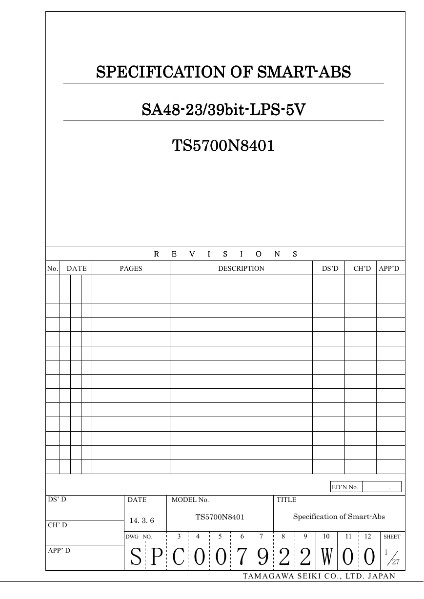
SPECIFICATION OF SMART
SPECIFICATION OF SMART----ABSABSABSABS
SPECIFICATION OF SMART
SPECIFICATION OF SMART
SA48----23/39bit
SA48
23/39bit----LPSLPSLPSLPS----5V5V5V5V
23/39bit
SA48
SA48
23/39bit
TS5700N8401
TS5700N8401
TS5700N8401
TS5700N8401
No. DATE
PAGES
DESCRIPTION
DS’D
CH’D
APP’D
R
R
R
R
E
E
E
E
V
V
V
V
I
I
I
I
S
S
S
S
I
I
I
I
O
O
O
O
N
N
N
N
S
S
S
S
DS’ D
CH’ D
APP’ D
DATE MODEL No. TITLE
ED’N No. . .
TS5700N8401
Specification of Smart-Abs
14. 3. 6
DWG NO. 3 4 5 6 7 8 9 10 11 12 SHEET
S P C 0 0 7 9 2 2 W 0 0
27
1
TA M A G AWA S E IK I C O . , LT D . J A PA N
�
1. Scope
Specification of Smart
Specification of
Smart----AbsAbsAbsAbs
Smart
Specification of
Specification of
Smart
TS5TS5TS5TS5700700700700N8401
N8401
N8401
N8401
This document defines the specification of the products described below.
(1) Name: Smart-Abs
(2) Model number: TS5700N8401
(3) Functional classification: SA48-23/39bit-LPS-5V
This specification is translated by original Japanese version. When Japanese and
English have a difference, we give priority to a Japanese version.
2. Basic Function
This Smart-Abs has basic functions as follows.
(1) This Smart-Abs is a full absolute encoder that has the resolution of 23 bits per
revolution and the multi-turn counting of 16 bits, as the total resolution of 39 bits,
and transmits the output of full absolute position data as serial digital data in
response to an external request. But when the battery is not connected, it
functions as a full absolute encoder that transmits the output of full absolute
position data with 23 bits per revolution as serial digital data in response to an
external request.
(2) It is capable of saving the multi-turn data and operating the multi-turn counter by
mean of connecting to a battery even when the main power supply is suddenly cut
off such as for a power outage.
(3) It is capable of writing any desired 762 bytes data into the EEPROM at any time.
(4) Serial communications are done by communication rate 2.5Mbps.
(5) The temperature on the encoder can be measured by using a part of the EEPROM
access function.
3. Environmental Conditions
Items
Specification
Remarks
Operating temperature
range
Storage temperature
range
Humidity
-10~ +85 ºC
-20~ +90 ºC
90 % RH max.
Vibration-
resistance
Test
condition
Shock-
resistance
Test
condition
5~ 58 Hz,
Double amplitude of 1.5 mm;
58~ 2,000 Hz, 98 m/s2
1,960 m/s2, 11 ms
---
---
At 40 ºC, 96 hours,
without condensation
2 hours for each axis,
total 6 hours
3 times for each
direction, total 18 times
DWG NO. 3 4 5 6 7 8 9 10 11 12 SHEET
S P C 0 0 7 9 2 2 W 0 0
2
第 版
TA M A G AWA S E IK I C O . , LT D . J A PA N
�
4. Mechanical Specification
Items
Specification
Remarks
Outline
OTD005891W00
---
Protecting structure
IP 50
IEC529
When shaft fitted
Items
Specification Ta=25 ºC
Remarks
Unit
Mass
Min.
Typ. Max.
---
---
0.3
Moment of inertia
---
6.5
---
For only main body,
except the cable
GD2/4
Friction torque
---
---
9.8
At 20 ºC
Allowable
Shaft
Load
Radial
Axial
Tilt
Permissible
rotational speed
Permissible
angular acceleration
-
-
-
-
-
-
27
8.7
0.1
---
---
6,000 ---
---
---
80,000
---
-
-
-
kg
x 10-6 kg・m2
x 10-3 N・m
N
N
°
min-1
rad/s2
Mechanical life
---
10,000
---
At 85℃, 6,000 min-1
(reference)
h
第 版
DWG NO. 3 4 5 6 7 8 9 10 11 12 SHEET
S P C 0 0 7 9 2 2 W 0 0
3
TA M A G AWA S E IK I C O . , LT D . J A PA N
�
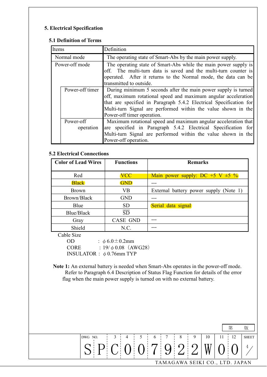
5. Electrical Specification
5.1 Definition of Terms
Items
Definition
Normal mode
The operating state of Smart-Abs by the main power supply.
Power-off mode
Power-off timer
Power-off
operation
The operating state of Smart-Abs while the main power supply is
off. The multi-turn data is saved and the multi-turn counter is
operated. After it returns to the Normal mode, the data can be
transmitted to outside.
During minimum 5 seconds after the main power supply is turned
off, maximum rotational speed and maximum angular acceleration
that are specified in Paragraph 5.4.2 Electrical Specification for
Multi-turn Signal are performed within the value shown in the
Power-off timer operation.
Maximum rotational speed and maximum angular acceleration that
are specified
in Paragraph 5.4.2 Electrical Specification for
Multi-turn Signal are performed within the value shown in the
Power-off operation.
5.2 Electrical Connections
Color of Lead Wires
Functions
Remarks
Red
Black
Brown
Brown/Black
Blue
Blue/Black
Gray
Shield
Cable Size
VCC
GND
VB
GND
SD
SD
Main power supply: DC +5 V ±5 %
---
External battery power supply (Note 1)
---
Serial data signal
CASE GND
N.C.
---
---
OD :φ6.0±0.2mm
CORE :19/φ0.08(AWG28)
INSULATOR:φ0.76mm TYP
Note 1: An external battery is needed when Smart-Abs operates in the power-off mode.
Refer to Paragraph 6.4 Description of Status Flag Function for details of the error
flag when the main power supply is turned on with no external battery.
第 版
DWG NO. 3 4 5 6 7 8 9 10 11 12 SHEET
S P C 0 0 7 9 2 2 W 0 0
4
TA M A G AWA S E IK I C O . , LT D . J A PA N
�
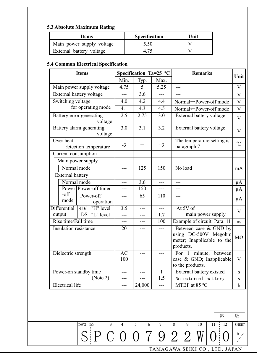
5.3 Absolute Maximum Rating
Items
Specification
Unit
Main power supply voltage
5.50
External battery voltage
4.75
V
V
5.4 Common Electrical Specification
Items
Main power supply voltage
External battery voltage
Switching voltage
for operating mode
Battery error generating
voltage
Battery alarm generating
voltage
Over heat
detection temperature
Current consumption
Main power supply
Normal mode
External battery
Normal mode
Power
-off
mode
Power-off timer
Power-off
operation
"H" level
SD/
DS "L" level
Differential
output
Rise time/Fall time
Insulation resistance
Dielectric strength
Power-on standby time
(Note 2)
Electrical life
---
---
---
---
3.5
---
---
20
AC
100
---
---
---
Specification Ta=25 ºC
Min.
4.75
Typ. Max.
5.25
5
Remarks
---
Unit
V
---
4.0
4.1
2.5
3.6
4.2
4.3
2.75
---
4.4
4.5
3.0
---
V
Normal→Power-off mode V
Normal←Power-off mode V
External battery voltage
V
3.0
3.1
3.2
External battery voltage
-3
-
+3
The temperature setting is
paragraph 7
125
150
No load
V
℃
mA
µA
µA
µA
V
---
---
110
---
---
---
3.6
150
65
---
---
---
---
At 5V of
main power supply
---
1.7
100 Example of circuit: Para. 11 ns
---
Between case & GND by
using DC-500V Megohm
meter; Inapplicable to the
products.
For 1 minute, between
case & GND; Inapplicable
to the products.
External battery existed
No external battery
MTBF at 85 ºC
MΩ
V
s
s
h
---
---
---
---
24,000
1
1.5
---
DWG NO. 3 4 5 6 7 8 9 10 11 12 SHEET
S P C 0 0 7 9 2 2 W 0 0
5
第 版
TA M A G AWA S E IK I C O . , LT D . J A PA N
�
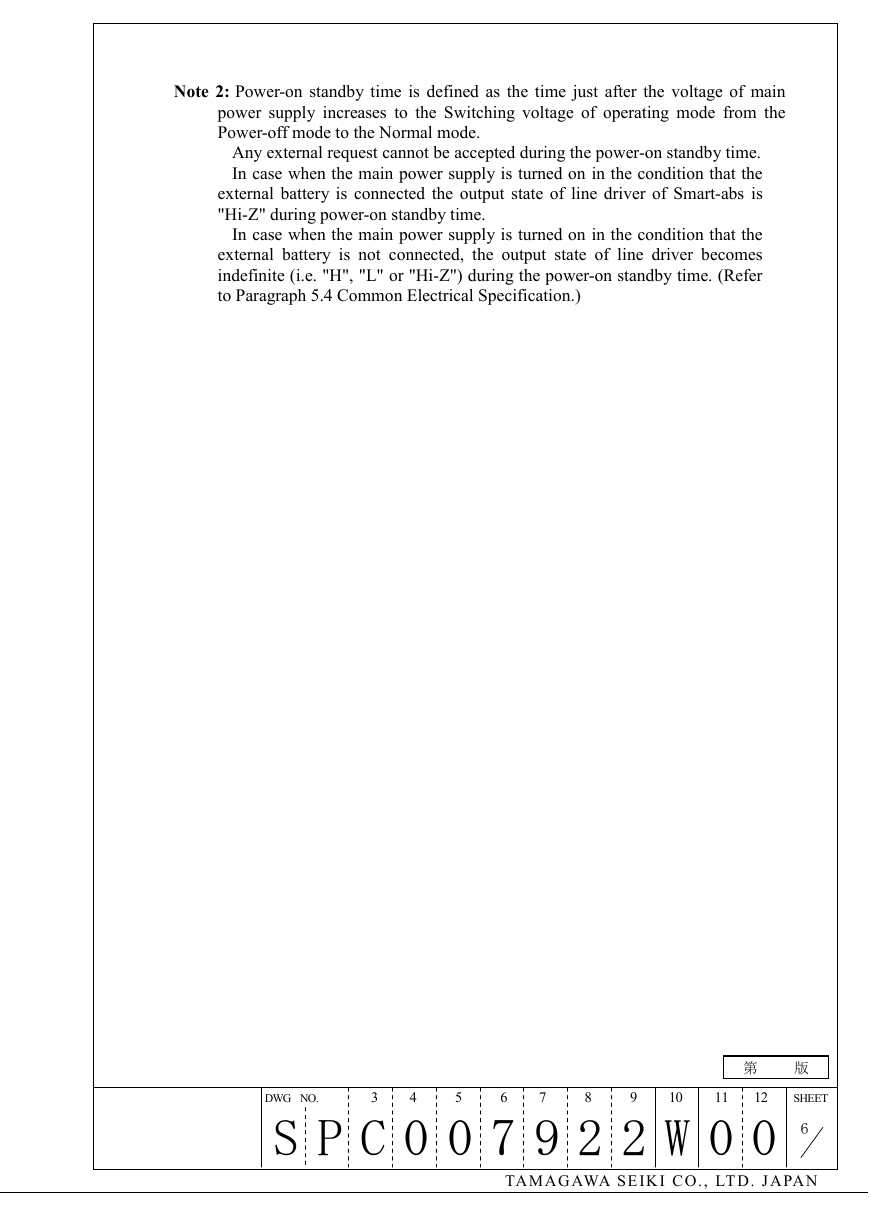
Note 2: Power-on standby time is defined as the time just after the voltage of main
power supply increases to the Switching voltage of operating mode from the
Power-off mode to the Normal mode.
Any external request cannot be accepted during the power-on standby time.
In case when the main power supply is turned on in the condition that the
external battery is connected the output state of line driver of Smart-abs is
"Hi-Z" during power-on standby time.
In case when the main power supply is turned on in the condition that the
external battery is not connected, the output state of line driver becomes
indefinite (i.e. "H", "L" or "Hi-Z") during the power-on standby time. (Refer
to Paragraph 5.4 Common Electrical Specification.)
第 版
DWG NO. 3 4 5 6 7 8 9 10 11 12 SHEET
S P C 0 0 7 9 2 2 W 0 0
6
TA M A G AWA S E IK I C O . , LT D . J A PA N
�
5.4.1 Electrical Specification for One Revolution Single
Items
Resolution
Maximum
rotational speed
Maximum angular
acceleration
Output code
Normal
mode
Normal
mode
Specification
Ta=25 ºC
223
6,000 min-1
Remarks
When main power supply is turned on at
the rotational speed of 100 min-1 or more,
the accuracy is 5 bits. (Note 3)
---
80,000 rad/s2
---
Pure binary
---
Incremental direction
Accumulated pitch error
Adjoining pitch error
CCW
±80 arc-sec
±40 arc-sec
In view from the shaft end of Smart- Abs
Taget value
Repeatability
at main power- on
±80 arc-sec
---
Note 3: When one revolution data of 223 is not assured, Full absolute status comes out
as a status flag. Refer to Paragraph 6.4 Description of Status Flag Function.
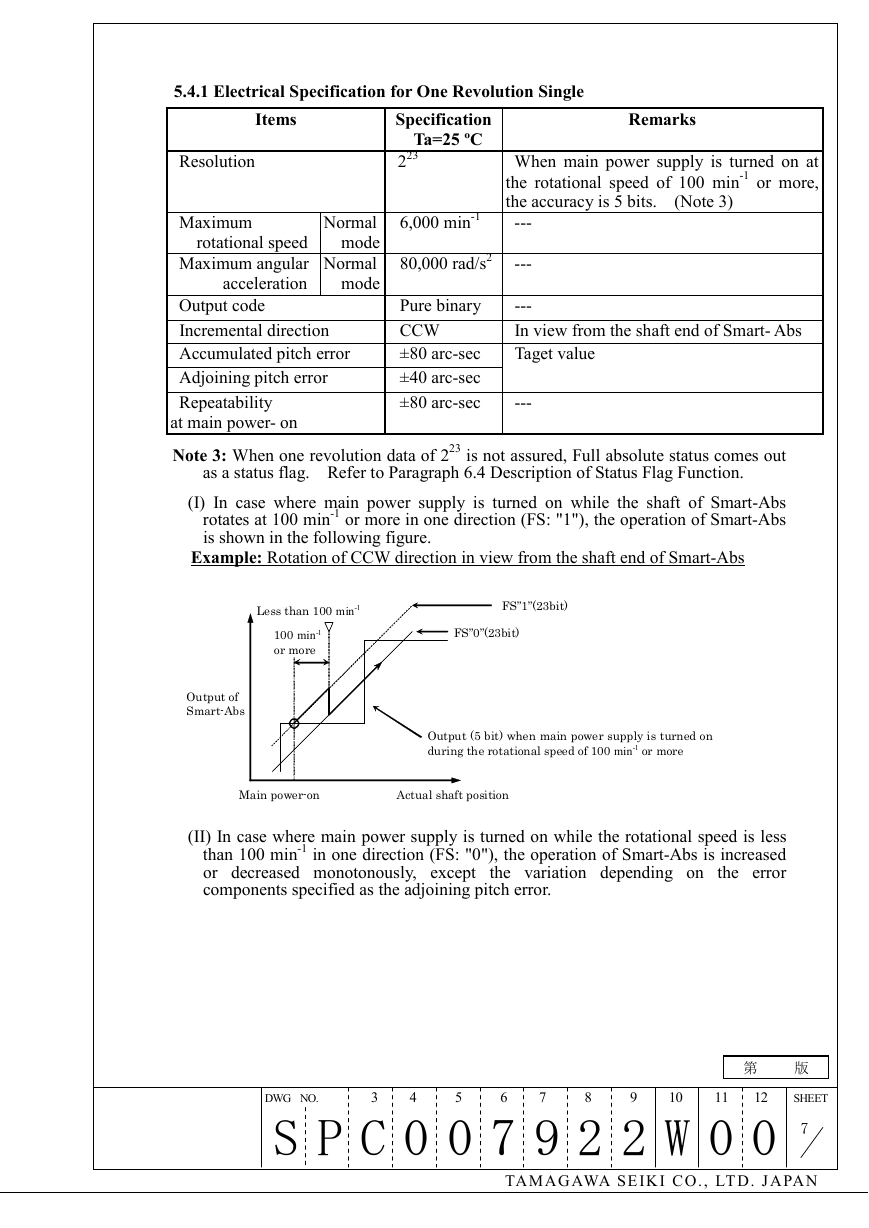
(I) In case where main power supply is turned on while the shaft of Smart-Abs
rotates at 100 min-1 or more in one direction (FS: "1"), the operation of Smart-Abs
is shown in the following figure.
Example: Rotation of CCW direction in view from the shaft end of Smart-Abs
Less than 100 min-1
100 min-1
or more
FS”1”(23bit)
FS”0”(23bit)
Output of
Smart-Abs
Output (5 bit) when main power supply is turned on
during the rotational speed of 100 min-1 or more
Main power-on
Actual shaft position
(II) In case where main power supply is turned on while the rotational speed is less
than 100 min-1 in one direction (FS: "0"), the operation of Smart-Abs is increased
or decreased monotonously, except the variation depending on the error
components specified as the adjoining pitch error.
第 版
DWG NO. 3 4 5 6 7 8 9 10 11 12 SHEET
S P C 0 0 7 9 2 2 W 0 0
7
TA M A G AWA S E IK I C O . , LT D . J A PA N
�
5.4.2 Electrical Specification for Multi-turn Signal
Items
Specification
Ta=25 ºC
Remarks
Resolution
Multi-turn counting range
Maximum rotational speed
1 C/T
216
6,000 min-1
6,000 min-1
Power-off
mode Power-off operation 6,000 min-1
Power-off timer
Normal mode
Normal mode
Maximum angular acceleration
80,000 rad/s2
80,000 rad/s2
Power-off
mode Power-off operation 4,000 rad/s2
Power-off timer
Output code
Incremental direction
Pure binary
CCW
---
0~ 65535 (Note 5,6)
---
Duration is 5 seconds
---
---
---
---
---
In view from the shaft end
of Smart-Abs
Note 5: When the battery error (BE) occurs, Counter overflow is returned to operate
normally by resetting its multi-turn data.
Valid Condition of Counter Overflow Flag
第 版
DWG NO. 3 4 5 6 7 8 9 10 11 12 SHEET
S P C 0 0 7 9 2 2 W 0 0
8
TA M A G AWA S E IK I C O . , LT D . J A PA N
�




 2023年江西萍乡中考道德与法治真题及答案.doc
 2012年重庆南川中考生物真题及答案.doc
 2013年江西师范大学地理学综合及文艺理论基础考研真题.doc
 2020年四川甘孜小升初语文真题及答案I卷.doc
 2020年注册岩土工程师专业基础考试真题及答案.doc
 2023-2024学年福建省厦门市九年级上学期数学月考试题及答案.doc
 2021-2022学年辽宁省沈阳市大东区九年级上学期语文期末试题及答案.doc
 2022-2023学年北京东城区初三第一学期物理期末试卷及答案.doc
 2018上半年江西教师资格初中地理学科知识与教学能力真题及答案.doc
 2012年河北国家公务员申论考试真题及答案-省级.doc
 2020-2021学年江苏省扬州市江都区邵樊片九年级上学期数学第一次质量检测试题及答案.doc
 2022下半年黑龙江教师资格证中学综合素质真题及答案.doc