Version 1.1.6
2010-08-31
Datasheet
LG4573B
Mobile Display Driver IC
for a 16M-Color WVGA TFT LCD Panel
1 General Description........................................................................................................ 4
2 Features ......................................................................................................................... 5
3 Block Diagram ................................................................................................................ 6
4 Pin Description ............................................................................................................... 7
4.1 Pin List ........................................................................................................................... 7
4.2 Pin Assignment.............................................................................................................. 10
4.3 Bump Coordinates ......................................................................................................... 11
4.4 Bump Arrangement ....................................................................................................... 19
5 Functional Description ................................................................................................. 20
5.1 SPI (Serial Peripheral Interface)...................................................................................... 20
5.1.1 Write/ Read Cycle Sequence ................................................................................... 20
5.2 MIPI DBI Type C ........................................................................................................... 22
5.2.1 Write Cycle Sequence ............................................................................................ 22
Read Cycle Sequence............................................................................................. 22
5.2.2
Break and Pause of Sequences ............................................................................... 23
5.2.3
5.3 MIPI DPI-2.................................................................................................................... 24
Interface Signals.................................................................................................... 24
Interface Color Coding ........................................................................................... 24
5.4 MIPI DSI....................................................................................................................... 25
DSI Layer Definitions ............................................................................................. 26
Command and Video Modes ................................................................................... 27
DSI Physical Layer (D-PHY) .................................................................................... 28
Interconnect ......................................................................................................... 28
DSI Protocol.......................................................................................................... 29
5.5 Backlight Control Function.............................................................................................. 38
CABC (Content Adaptive Brightness Control) ............................................................ 38
Brightness Control Block and CABC Block ................................................................. 39
5.6 LCD Power Supply Circuit ............................................................................................... 42
Voltage Setting Pattern Diagram ............................................................................. 42
Power On/Off Sequence ......................................................................................... 43
Display On Sequence ............................................................................................. 44
Sleep In, Out Sequence.......................................................................................... 45
DSTB IN, DSTB OUT, Display On Sequence.............................................................. 46
5.7 Gamma Correction Function ........................................................................................... 47
Grayscale Generation Unit Configuration .................................................................. 48
Gamma Correction Register .................................................................................... 49
Ladder Resistors and 8-to-1 Selector ....................................................................... 51
5.8 Oscillator ...................................................................................................................... 56
5.9 OTP Control .................................................................................................................. 57
6 Commands.................................................................................................................... 61
6.1 Command List ............................................................................................................... 61
6.2 Command Description.................................................................................................... 66
00h – No Operation ............................................................................................... 66
01h – Software Reset............................................................................................. 67
0Ah – Read Display Power Mode ............................................................................. 68
0Bh – Read Display MADCTL................................................................................... 69
5.6.1
5.6.2
5.6.3
5.6.4
5.6.5
5.3.1
5.3.2
5.4.1
5.4.2
5.4.3
5.4.4
5.4.5
5.5.1
5.5.2
5.7.1
5.7.2
5.7.3
6.2.1
6.2.2
6.2.3
6.2.4
�
LG4573B
Ver. 1.1.6
0Ch – Read Display Pixel Format............................................................................. 70
6.2.5
0Dh – Read Display Image Mode ............................................................................ 71
6.2.6
10h – Sleep In....................................................................................................... 72
6.2.7
11h – Sleep Out .................................................................................................... 73
6.2.8
13h – Normal Display Mode On............................................................................... 74
6.2.9
6.2.10 20h – Display Inversion Off .................................................................................... 75
6.2.11 21h – Display Inversion On..................................................................................... 76
6.2.12 28h – Display Off................................................................................................... 77
6.2.13 29h – Display On ................................................................................................... 78
6.2.14 36h – Set Address Mode......................................................................................... 79
6.2.15 3Ah – Interface Pixel Format .................................................................................. 81
6.2.16 51h – Write Display Brightness ............................................................................... 82
6.2.17 52h – Read Display Brightness Value....................................................................... 83
6.2.18 53h – Write Control Display .................................................................................... 84
6.2.19 54h – Read Display Brightness Value....................................................................... 85
6.2.20 55h – Write Content Adaptive Brightness Control...................................................... 86
6.2.21 56h – Read Content Adaptive Brightness Control ...................................................... 87
6.2.22 5Eh – Write CABC Minimum Brightness.................................................................... 88
6.2.23 5Fh – Read CABC Minimum Brightness .................................................................... 89
6.2.24 A1h – Read DDB Start............................................................................................ 90
6.2.25 B1h – RGB Interface Setting ................................................................................... 91
6.2.26 B2h – Panel Characteristics Setting.......................................................................... 93
6.2.27 B3h – Panel Drive Setting....................................................................................... 94
6.2.28 B4h – Display Mode Control.................................................................................... 95
6.2.29 B5h – Display Control 1.......................................................................................... 96
6.2.30 B6h – Display Control 2.......................................................................................... 97
6.2.31 C0h – Internal Oscillator Setting............................................................................ 111
6.2.32 C1h – Power Control 1 ......................................................................................... 112
6.2.33 C2h – Power Control 2 ......................................................................................... 113
6.2.34 C3h – Power Control 3 ......................................................................................... 114
6.2.35 C4h – Power Control 4 ......................................................................................... 119
6.2.36 C5h – Power Control 5 ......................................................................................... 123
6.2.37 C6h – Power Control 6 ......................................................................................... 125
6.2.38 C7h – Offset Cancelling Control............................................................................. 127
6.2.39 C8h – Backlight Control ........................................................................................ 128
6.2.40 D0h – Positive Gamma Curve for Red .................................................................... 129
6.2.41 D1h – Negative Gamma Curve for Red .................................................................. 130
6.2.42 D2h – Positive Gamma Curve for Green ................................................................. 131
6.2.43 D3h – Negative Gamma Curve for Green ............................................................... 132
6.2.44 D4h – Positive Gamma Curve for Blue ................................................................... 133
6.2.45 D5h – Negative Gamma Curve for Blue.................................................................. 134
6.2.46 F0h – Test Register 1........................................................................................... 135
6.2.47 F8h – OTP 1........................................................................................................ 136
6.2.48 F9h – OTP 2........................................................................................................ 137
6.2.49 FAh – OTP 3........................................................................................................ 138
7 Electrical Characteristics............................................................................................ 139
7.1 Absolute Maximum Ratings........................................................................................... 139
7.2 Power Supply Specifications ......................................................................................... 140
7.3 DC Characteristics ....................................................................................................... 141
7.4 AC Characteristics........................................................................................................ 142
7.4.1 MIPI HS Receiver Characteristics........................................................................... 142
7.4.2 MIPI LP Receiver Characteristics ........................................................................... 143
7.4.3 MIPI LP Transmitter Characteristics....................................................................... 144
Serial Peripheral Interface Characteristics .............................................................. 146
7.4.4
Reset Characteristics............................................................................................ 146
7.4.5
RGB Interface Timing Characteristics..................................................................... 147
7.4.6
LGE Confidential
2
�
LG4573B
Ver. 1.1.6
8 Reference Applications .............................................................................................. 148
8.1 Configuration of Power Supply Circuit............................................................................ 148
9 History of Revision ..................................................................................................... 151
LGE Confidential
3
�
LG4573B
Ver. 1.1.6
General Description
1
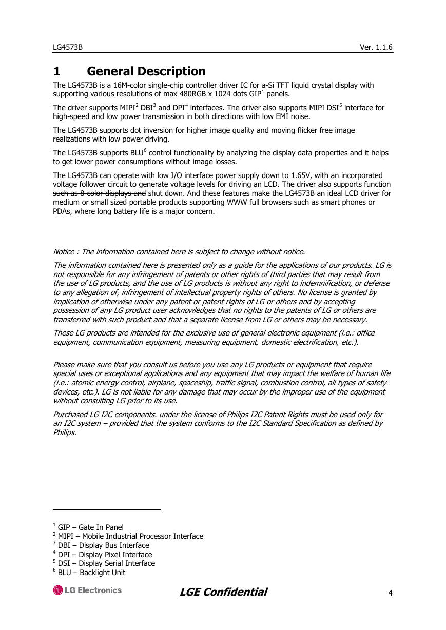
The LG4573B is a 16M-color single-chip controller driver IC for a-Si TFT liquid crystal display with
supporting various resolutions of max 480RGB x 1024 dots GIP1 panels.
The driver supports MIPI2 DBI3 and DPI4 interfaces. The driver also supports MIPI DSI5 interface for
high-speed and low power transmission in both directions with low EMI noise.
The LG4573B supports dot inversion for higher image quality and moving flicker free image
realizations with low power driving.
The LG4573B supports BLU6 control functionality by analyzing the display data properties and it helps
to get lower power consumptions without image losses.
The LG4573B can operate with low I/O interface power supply down to 1.65V, with an incorporated
voltage follower circuit to generate voltage levels for driving an LCD. The driver also supports function
such as 8-color displays and shut down. And these features make the LG4573B an ideal LCD driver for
medium or small sized portable products supporting WWW full browsers such as smart phones or
PDAs, where long battery life is a major concern.
Notice : The information contained here is subject to change without notice.
The information contained here is presented only as a guide for the applications of our products. LG is
not responsible for any infringement of patents or other rights of third parties that may result from
the use of LG products, and the use of LG products is without any right to indemnification, or defense
to any allegation of, infringement of intellectual property rights of others. No license is granted by
implication of otherwise under any patent or patent rights of LG or others and by accepting
possession of any LG product user acknowledges that no rights to the patents of LG or others are
transferred with such product and that a separate license from LG or others may be necessary.
These LG products are intended for the exclusive use of general electronic equipment (i.e.: office
equipment, communication equipment, measuring equipment, domestic electrification, etc.).
Please make sure that you consult us before you use any LG products or equipment that require
special uses or exceptional applications and any equipment that may impact the welfare of human life
(i.e.: atomic energy control, airplane, spaceship, traffic signal, combustion control, all types of safety
devices, etc.). LG is not liable for any damage that may occur by the improper use of the equipment
without consulting LG prior to its use.
Purchased LG I2C components. under the license of Philips I2C Patent Rights must be used only for
an I2C system – provided that the system conforms to the I2C Standard Specification as defined by
Philips.
1 GIP – Gate In Panel
2 MIPI – Mobile Industrial Processor Interface
3 DBI – Display Bus Interface
4 DPI – Display Pixel Interface
5 DSI – Display Serial Interface
6 BLU – Backlight Unit
LGE Confidential
4
�
LG4573B
Ver. 1.1.6
2
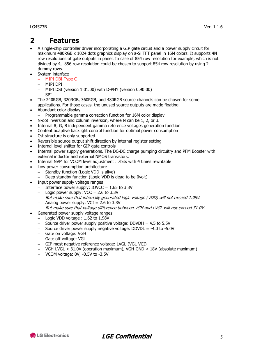
• A single-chip controller driver incorporating a GIP gate circuit and a power supply circuit for
Features
maximum 480RGB x 1024 dots graphics display on a-Si TFT panel in 16M colors. It supports 4N
row resolutions of gate outputs in panel. In case of 854 row resolution for example, which is not
divided by 4, 856 row resolution could be chosen to support 854 row resolution by using 2
dummy rows.
• System interface
− MIPI DBI Type C
− MIPI DPI
− MIPI DSI (version 1.01.00) with D-PHY (version 0.90.00)
− SPI
• The 240RGB, 320RGB, 360RGB, and 480RGB source channels can be chosen for some
applications. For those cases, the unused source outputs are made floating.
• Abundant color display
− Programmable gamma correction function for 16M color display
• N-dot inversion and column inversion, where N can be 1, 2, or 3.
•
Internal R, G, B independent gamma reference voltages generation function
• Content adaptive backlight control function for optimal power consumption
• Cst structure is only supported.
• Reversible source output shift direction by internal register setting
•
•
Internal level shifter for GIP gate controls
Internal power supply generations. The DC-DC charge pumping circuitry and PFM Booster with
external inductor and external NMOS transistors.
Internal NVM for VCOM level adjustment : 7bits with 4 times rewritable
Low power consumption architecture
− Standby function (Logic VDD is alive)
− Deep standby function (Logic VDD is dead to be 0volt)
Input power supply voltage ranges
−
− Logic power supply: VCC = 2.6 to 3.3V
Interface power supply: IOVCC = 1.65 to 3.3V
•
•
•
But make sure that internally generated logic voltage (VDD) will not exceed 1.98V.
− Analog power supply: VCI = 2.6 to 3.3V
But make sure that voltage difference between VGH and LVGL will not exceed 31.0V.
• Generated power supply voltage ranges
− Logic VDD voltage : 1.62 to 1.98V
− Source driver power supply positive voltage: DDVDH = 4.5 to 5.5V
− Source driver power supply negative voltage: DDVDL = -4.0 to -5.0V
− Gate on voltage: VGH
− Gate off voltage: VGL
− GIP most negative reference voltage: LVGL (VGL-VCI)
− VGH-LVGL < 31.0V (operation maximum), VGH-GND < 18V (absolute maximum)
− VCOM voltage: 0V, -0.5V to -3.5V
LGE Confidential
5
�
LG4573B
Ver. 1.1.6
3
Block Diagram
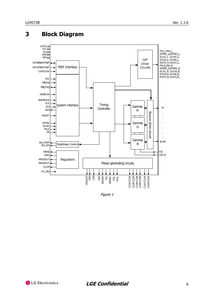
Figure 1
LGE Confidential
6
�
Ver. 1.1.6
Pin Description
I/O Connected to
Description
I
MPU
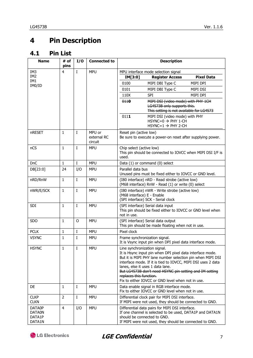
MPU interface mode selection signal
Register Access
IM[3:0]
Pixel Data
LG4573B
4
4.1
Name
IM3
IM2
IM1
IM0/ID
Pin List
# of
pins
4
1
1
I
I
MPU or
external RC
circuit
MPU
1
24
I
I/O
MPU
MPU
MPU
MPU
MPU
I
I
I
O
MPU
I
I
I
I
I
MPU
MPU
MPU
MPU
MPU
I/O
MPU
1
1
1
1
1
1
1
1
2
4
nRESET
nCS
DnC
DB[23:0]
nRD/RnW
nWR/E/SCK
SDI
SDO
PCLK
VSYNC
HSYNC
DE
CLKP
CLKN
DATA0P
DATA0N
DATA1P
DATA1N
0100
0101
110X
0110
0111
MIPI DPI
MIPI DSI
MIPI DPI
MIPI DBI Type C
MIPI DBI Type C
SPI
MIPI DSI (video mode) with PHY 1CH
LG4573B only supports this.
This setting is not available for LG4573
MIPI DSI (video mode) with PHY
HSYNC=0 PHY 1-CH
HSYNC=1 PHY 2-CH
Reset pin (active low)
Be sure to execute a power-on reset after supplying power.
Chip select (active low)
This pin should be connected to IOVCC when MIPI DSI I/F is
used.
Data (1) or command (0) select
Parallel data bus
Unused pins must be fixed either to IOVCC or GND level.
(I80 interface) nRD - Read strobe (active low)
(M68 interface) RnW - Read (1) or write (0) select
(I80 interface) nWR - Write strobe (active low)
(M68 interface) E - Enable
(SPI interface) SCK - Serial clock
(SPI interface) Serial data input
This pin should be fixed either to IOVCC or GND level when
not in use.
(SPI interface) Serial data output
This pin should be made floating when not in use.
Pixel clock
Frame synchronization signal.
It is Vsync input pin when DPI pixel data interface mode.
Line synchronization signal.
It is Hsync input pin when DPI pixel data interface mode.
But it is MIPI PHY lane number selection pin when MIPI DSI
interface mode. If it is tied to IOVCC, MIPI DSI uses 2 data
lanes, else it uses 1 data lane.
But LG4573B don’t need HSYNC pin setting and IM setting
replaces this function.
Fix to either IOVCC or GND level when not in use.
Data enable signal in RGB interface mode.
Fix to either IOVCC or GND level when not in use.
Differential clock pair for MIPI DSI interface.
If MIPI were not used, they should be connected to GND.
Differential data pairs for MIPI DSI interface.
If one channel is selected to be used, DATA1P and DATA1N
should be connected to GND.
If MIPI were not used, they should be connected to GND.
LGE Confidential
7
�
Ver. 1.1.6
I/O Connected to
Description
GND
BLU
BLU
GND
IOVCC or GND When VCI<2.9V, then V12_SEL=GND is recommended.
When VCI>2.9V, then V12_SEL=IOVCC is recommended.
This pin should not be floating in any case.
Test pin
Fix to GND level in normal operation mode
Test pin
Fix to GND level in normal operation mode
BLU enable (active HIGH)
If not used, leave this pin open.
BLU PWM signal
If not used, leave this pin open.
Source driver output pins
Signals for right side GIP on panel view (Left side in IC
bump view)
Unused pins should be left open.
LCD
GIP
1440 O
8
O
# of
pins
1
1
1
1
1
I
I
I
O
O
LG4573B
Name
V12_SEL
TEST1
TEST2
BLU_EN
BLU_PWM
S1 to S1440
FW_L
BW_L
GVST1_L
GVST2_L
GCLK#_L
where
#=1,2,3,4
FW_R
BW_R
GVST1_R
GVST2_R
GCLK#_R
where
#=1,2,3,4
VBIAS
LVGL
VGL
VGH
DDVDL
DDVDH
VCL
IOVCC
VCC
VDD
VDDOUT
VSS
VCI
VCOM
8
O
GIP
Signals for Right side GIP on panel view (Right side in IC
bump view)
Unused pins should be left open.
1
1
1
1
1
1
1
1
1
1
1
1
1
1
O
GIP
I
I
I
I
I
I
I
I
I
I/O
I
I
O
GIP
Power supply
Power supply
Power supply
Stabilizing
capacitor and
VDD
Power supply
Power supply
TFT panel
common
electrode
Bias voltage for some special GIP circuits.
If not used, leave this pin open.
Most negative voltage for some special GIP circuits.
If not used, connect to VGL
A supply voltage to drive gate lines of the TFT panel.
A supply voltage to drive gate lines of the TFT panel.
Power supply for the source driver’s LCD output unit
Power supply for the source driver’s LCD output unit and an
input voltage to generate DDVDL voltage.
Power supply voltage for the level shifter circuits.
Power supply to the interface pins: IOVCC = 1.65 to 3.3V.
In case of COG, connect to VCC on the FPC if IOVCC = VCC
to prevent noise.
Power supply to generate the internal logic power supply
VDD.
VCC = 2.6 to 3.3V
Generated power supply for the internal logic.
Internal logic regulator output. Connect VDD to a stabilizing
capacitor.
VSS=0.
Supply voltage to the analog circuit.
Connect to an external power supply of 2.6 to 3.0V.
Supply voltage to the common electrode of TFT panel.
LGE Confidential
8
�


 2023年江西萍乡中考道德与法治真题及答案.doc
 2012年重庆南川中考生物真题及答案.doc
 2013年江西师范大学地理学综合及文艺理论基础考研真题.doc
 2020年四川甘孜小升初语文真题及答案I卷.doc
 2020年注册岩土工程师专业基础考试真题及答案.doc
 2023-2024学年福建省厦门市九年级上学期数学月考试题及答案.doc
 2021-2022学年辽宁省沈阳市大东区九年级上学期语文期末试题及答案.doc
 2022-2023学年北京东城区初三第一学期物理期末试卷及答案.doc
 2018上半年江西教师资格初中地理学科知识与教学能力真题及答案.doc
 2012年河北国家公务员申论考试真题及答案-省级.doc
 2020-2021学年江苏省扬州市江都区邵樊片九年级上学期数学第一次质量检测试题及答案.doc
 2022下半年黑龙江教师资格证中学综合素质真题及答案.doc