logo资料库

SAMSUNG TLC K9ACGD8UXA.pdf

第1页 / 共105页
第2页 / 共105页
第3页 / 共105页
第4页 / 共105页
第5页 / 共105页
第6页 / 共105页
第7页 / 共105页
第8页 / 共105页
资料共105页,剩余部分请下载后查看
64Gb A-die Toggle NAND Flash
1.0 INTRODUCTION
1.1 Features
1.2 Product List
1.3 General Description
1.4 Toggle DDR Interface according to Data Transfer Rate
1.5 Definitions and Abbreviations
1.6 Diagram Legend
1.7 Pin Configuration (TSOP1)
1.7.1 Package Dimensions
1.8 Pin Configuration (TSOP1)
1.8.1 Package Dimensions
2.0 PHYSICAL INTERFACE
2.1 Pin Description
2.2 Valid Block
2.3 Absolute Maximum DC Rating
2.4 Operating Temperature Condition
2.5 Recommended Operating Conditions
2.6 AC Overshoot/Undershoot Requirements
2.7 DC Operating Characteristics
2.8 AC & DC Input Measurement Levels
2.9 VREF Tolerances
2.10 Differential Input/Output AC Characteristics (1.8VccQ only)
2.11 Input/Output Capacitance(TA=25°C, VCC=3.3V, f=100MHz)
2.12 DQ Driver Strength
2.13 Input/Output Slew rate
2.14 R/B and SR[6] Relationship
2.15 Write Protect
3.0 MEMORY ORGANIZATION
3.1 Addressing
3.1.1 Plane Addressing
3.2 Factory Defect Mapping
3.2.1 Device Requirements
3.2.2 Host Requirements
3.3 Error In Write or Read Operation
3.4 Addressing For Program Operation
4.0 FUNCTION DESCRIPTION
4.1 DATA PROTECTION AND POWER TRANSITION SEQUENCE
4.1.1 Data Protection
4.1.2 Power Up Sequence
4.1.3 Power Down Sequence
4.2 Mode Selection
4.3 General Timing
4.3.1 Command Latch Cycle
4.3.2 Address Latch Cycle
4.3.3 Basic Data Input Timing
4.3.4 Basic Data Output Timing
4.3.5 Read ID Operation
4.3.6 Read Status Cycle
4.3.6.1 Read Status cycle before Toggle DDR setting at Initialization sequence by FFh command
4.3.7 Set Feature
4.3.8 Get Feature
4.3.9 Page Read Operation
4.3.10 Page Program Operation(1/2)
4.3.11 Page Program Operation(2/2)
4.4 AC Test Condition
4.5 AC Timing Characteristics
4.5.1 Timing Parameters Description
4.5.2 Timing Parameters Table
4.5.3 Read/Program / Erase Characteristics
5.0 COMMAND DESCRIPTION AND DEVICE OPERATION
5.1 Basic Command Sets
5.2 Basic Operation
5.2.1 Page Read Operation
5.2.1.1 Page Read Operation with Random Data Output
5.2.1.2 Data Out After Read Status
5.2.2 Sequential Cache Read Operation
5.2.3 Random Cache Read Operation
5.2.4 Fast 4KB Read (Half page Read)
5.2.5 Page Program Operation
5.2.5.1 Program Operation with Random Data Input
5.2.6 Cache Program Operation
5.2.7 Block Erase Operation
5.2.8 Copy-Back Program Operation
5.2.8.1 Copy-Back Program Operation with Random Data Input
5.2.9 Set Feature Operation
5.2.9.1 Toggle 2.0 specific setting (02h)
5.2.9.2 Driver strength setting (10h)
5.2.9.3 External VPP (30h)
5.2.10 Get Feature Operation
5.2.11 Read ID Operation
5.2.11.1 00h Address ID Definition
5.2.11.1.1 00h Address ID Cycle
5.2.11.2 40h Address ID Definition
5.2.12 Read Status Operation
5.2.13 Reset Operation
5.2.14 Reset LUN operation
5.3 Extended Operation
5.3.1 Extended Command Sets
5.3.2 Two-Plane Page Read Operation
5.3.3 Unaligned Two-plane operation
5.3.4 Two-Plane Sequential Cache Read Operation
5.3.5 Two-Plane Random Cache Read
5.3.6 Two-Plane Page Program Operation
5.3.7 Two-Plane Cache Program Operation(1/2)
5.3.8 Two-Plane Cache Program Operation(2/2)
5.3.9 Two-Plane Block Erase Operation
5.3.10 Two-Plane Copy-Back Program Operation(1/4)
5.3.11 Two-Plane Copy-Back Program Operation(2/4)
5.3.12 Two-Plane Copy-Back Program Operation(3/4)
5.3.13 Two-Plane Copy-Back Program Operation(4/4)
5.3.14 Device Identification Table Read Operation
5.3.14.1 Device Identification Table Definition
5.3.15 Read Status Enhanced
5.3.16 Read LUN #0 Status Operation
5.3.17 Read LUN #1 Status Operation
5.3.18 Register Read Out Mode 1
5.3.19 Two-Plane Register Read Out Mode 1
5.4 Interleaving Operation
5.4.1 Interleaving Page Program
5.4.2 Interleaving Page Read
5.4.3 Interleaving Block Erase
5.4.4 Interleaving Two-Plane Page Program(1/3)
5.4.5 Interleaving Two-Plane Page Program(2/3)
5.4.6 Interleaving Two-Plane Page Program(3/3)
5.4.7 Interleaving Two-Plane page Read
5.4.8 Interleaving Two-Plane Block Erase
5.4.9 Interleaving Read to Page Program
5.4.10 Interleaving Copy-Back Program (1/3)
5.4.11 Interleaving Copy-Back Program (2/3)
5.4.12 Interleaving Copy-Back Program (3/3)
5.4.13 Interleaving Two-Plane Copy Back Program(1/6)
5.4.14 Interleaving Two-Plane Copy Back Program(2/6)
5.4.15 Interleaving Two-Plane Copy Back Program(3/6)
5.4.16 Interleaving Two-Plane Copy Back Program(4/6)
5.4.17 Interleaving Two-Plane Copy Back Program(5/6)
5.4.18 Interleaving Two-Plane Copy Back Program(6/6)
5.5 Ready/Busy
5.6 Mode Change
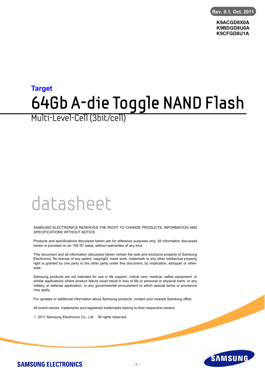
Rev. 0.1, Oct. 2011 K9ACGD8X0A K9BDGD8U0A K9CFGD8U1A Target 64Gb A-die Toggle NAND Flash Multi-Level-Cell (3bit/cell) datasheet SAMSUNG ELECTRONICS RESERVES THE RIGHT TO CHANGE PRODUCTS, INFORMATION AND SPECIFICATIONS WITHOUT NOTICE. Products and specifications discussed herein are for reference purposes only. All information discussed herein is provided on an "AS IS" basis, without warranties of any kind. This document and all information discussed herein remain the sole and exclusive property of Samsung Electronics. No license of any patent, copyright, mask work, trademark or any other intellectual property right is granted by one party to the other party under this document, by implication, estoppel or other- wise. Samsung products are not intended for use in life support, critical care, medical, safety equipment, or similar applications where product failure could result in loss of life or personal or physical harm, or any military or defense application, or any governmental procurement to which special terms or provisions may apply. For updates or additional information about Samsung products, contact your nearest Samsung office. All brand names, trademarks and registered trademarks belong to their respective owners. ⓒ 2011 Samsung Electronics Co., Ltd. All rights reserved. - 1 -
K9ACGD8X0A K9BDGD8U0A K9CFGD8U1A Revision History datasheet Target Rev. 0.1 FLASH MEMORY Revision No. History Draft Date Remark Edited by Reviewed by 0.0 0.1 1. Initial issue 1. Errata corrected 2. 2.4 Absolute Maximum DC Rating part is changed. Aug. 16, 2011 Target H.K.Kim M.K.Kook Y.E.Yoon Oct. 21, 2011 Target H.K.Kim Y.E.Yoon - 2 -
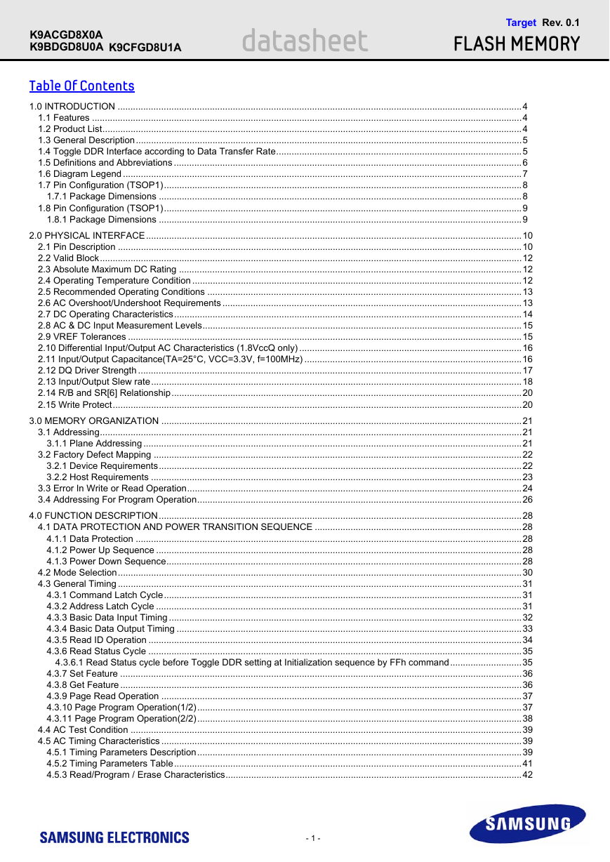
K9ACGD8X0A K9BDGD8U0A K9CFGD8U1A datasheet Target Rev. 0.1 FLASH MEMORY Table Of Contents 1.0 INTRODUCTION ..............................................................................................................................................................4 1.1 Features ........................................................................................................................................................................4 1.2 Product List....................................................................................................................................................................4 1.3 General Description.......................................................................................................................................................5 1.4 Toggle DDR Interface according to Data Transfer Rate................................................................................................5 1.5 Definitions and Abbreviations ........................................................................................................................................6 1.6 Diagram Legend ............................................................................................................................................................7 1.7 Pin Configuration (TSOP1)............................................................................................................................................8 1.7.1 Package Dimensions ..............................................................................................................................................8 1.8 Pin Configuration (TSOP1)............................................................................................................................................9 1.8.1 Package Dimensions ..............................................................................................................................................9 2.0 PHYSICAL INTERFACE...................................................................................................................................................10 2.1 Pin Description ..............................................................................................................................................................10 2.2 Valid Block.....................................................................................................................................................................12 2.3 Absolute Maximum DC Rating ......................................................................................................................................12 2.4 Operating Temperature Condition .................................................................................................................................12 2.5 Recommended Operating Conditions ...........................................................................................................................13 2.6 AC Overshoot/Undershoot Requirements .....................................................................................................................13 2.7 DC Operating Characteristics........................................................................................................................................14 2.8 AC & DC Input Measurement Levels.............................................................................................................................15 2.9 VREF Tolerances ..........................................................................................................................................................15 2.10 Differential Input/Output AC Characteristics (1.8VccQ only) .......................................................................................16 2.11 Input/Output Capacitance(TA=25°C, VCC=3.3V, f=100MHz) .....................................................................................16 2.12 DQ Driver Strength ......................................................................................................................................................17 2.13 Input/Output Slew rate.................................................................................................................................................18 2.14 R/B and SR[6] Relationship.........................................................................................................................................20 2.15 Write Protect................................................................................................................................................................20 3.0 MEMORY ORGANIZATION .............................................................................................................................................21 3.1 Addressing.....................................................................................................................................................................21 3.1.1 Plane Addressing ....................................................................................................................................................21 3.2 Factory Defect Mapping ................................................................................................................................................22 3.2.1 Device Requirements..............................................................................................................................................22 3.2.2 Host Requirements .................................................................................................................................................23 3.3 Error In Write or Read Operation...................................................................................................................................24 3.4 Addressing For Program Operation...............................................................................................................................26 4.0 FUNCTION DESCRIPTION..............................................................................................................................................28 4.1 DATA PROTECTION AND POWER TRANSITION SEQUENCE .................................................................................28 4.1.1 Data Protection .......................................................................................................................................................28 4.1.2 Power Up Sequence ...............................................................................................................................................28 4.1.3 Power Down Sequence...........................................................................................................................................28 4.2 Mode Selection..............................................................................................................................................................30 4.3 General Timing ..............................................................................................................................................................31 4.3.1 Command Latch Cycle............................................................................................................................................31 4.3.2 Address Latch Cycle ...............................................................................................................................................31 4.3.3 Basic Data Input Timing ..........................................................................................................................................32 4.3.4 Basic Data Output Timing .......................................................................................................................................33 4.3.5 Read ID Operation ..................................................................................................................................................34 4.3.6 Read Status Cycle ..................................................................................................................................................35 4.3.6.1 Read Status cycle before Toggle DDR setting at Initialization sequence by FFh command............................35 4.3.7 Set Feature .............................................................................................................................................................36 4.3.8 Get Feature .............................................................................................................................................................36 4.3.9 Page Read Operation .............................................................................................................................................37 4.3.10 Page Program Operation(1/2)...............................................................................................................................37 4.3.11 Page Program Operation(2/2)...............................................................................................................................38 4.4 AC Test Condition .........................................................................................................................................................39 4.5 AC Timing Characteristics .............................................................................................................................................39 4.5.1 Timing Parameters Description...............................................................................................................................39 4.5.2 Timing Parameters Table........................................................................................................................................41 4.5.3 Read/Program / Erase Characteristics....................................................................................................................42 - 1 -
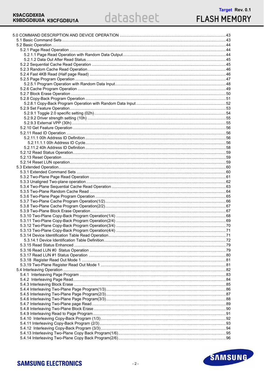
K9ACGD8X0A K9BDGD8U0A K9CFGD8U1A datasheet Target Rev. 0.1 FLASH MEMORY 5.0 COMMAND DESCRIPTION AND DEVICE OPERATION ................................................................................................43 5.1 Basic Command Sets ....................................................................................................................................................43 5.2 Basic Operation .............................................................................................................................................................44 5.2.1 Page Read Operation .............................................................................................................................................44 5.2.1.1 Page Read Operation with Random Data Output.............................................................................................44 5.2.1.2 Data Out After Read Status ..............................................................................................................................45 5.2.2 Sequential Cache Read Operation .........................................................................................................................45 5.2.3 Random Cache Read Operation.............................................................................................................................46 5.2.4 Fast 4KB Read (Half page Read) ...........................................................................................................................46 5.2.5 Page Program Operation ........................................................................................................................................47 5.2.5.1 Program Operation with Random Data Input....................................................................................................48 5.2.6 Cache Program Operation ......................................................................................................................................49 5.2.7 Block Erase Operation ............................................................................................................................................50 5.2.8 Copy-Back Program Operation ...............................................................................................................................51 5.2.8.1 Copy-Back Program Operation with Random Data Input .................................................................................52 5.2.9 Set Feature Operation.............................................................................................................................................53 5.2.9.1 Toggle 2.0 specific setting (02h).......................................................................................................................54 5.2.9.2 Driver strength setting (10h) .............................................................................................................................55 5.2.9.3 External VPP (30h) ...........................................................................................................................................55 5.2.10 Get Feature Operation ..........................................................................................................................................56 5.2.11 Read ID Operation ................................................................................................................................................56 5.2.11.1 00h Address ID Definition ...............................................................................................................................56 5.2.11.1.1 00h Address ID Cycle...............................................................................................................................56 5.2.11.2 40h Address ID Definition ...............................................................................................................................58 5.2.12 Read Status Operation..........................................................................................................................................59 5.2.13 Reset Operation ....................................................................................................................................................59 5.2.14 Reset LUN operation.............................................................................................................................................59 5.3 Extended Operation.......................................................................................................................................................60 5.3.1 Extended Command Sets .......................................................................................................................................60 5.3.2 Two-Plane Page Read Operation ...........................................................................................................................61 5.3.3 Unaligned Two-plane operation ..............................................................................................................................62 5.3.4 Two-Plane Sequential Cache Read Operation .......................................................................................................63 5.3.5 Two-Plane Random Cache Read ...........................................................................................................................64 5.3.6 Two-Plane Page Program Operation ......................................................................................................................65 5.3.7 Two-Plane Cache Program Operation(1/2).............................................................................................................66 5.3.8 Two-Plane Cache Program Operation(2/2).............................................................................................................67 5.3.9 Two-Plane Block Erase Operation ..........................................................................................................................67 5.3.10 Two-Plane Copy-Back Program Operation(1/4) ...................................................................................................68 5.3.11 Two-Plane Copy-Back Program Operation(2/4) ...................................................................................................69 5.3.12 Two-Plane Copy-Back Program Operation(3/4) ...................................................................................................70 5.3.13 Two-Plane Copy-Back Program Operation(4/4) ...................................................................................................71 5.3.14 Device Identification Table Read Operation..........................................................................................................71 5.3.14.1 Device Identification Table Definition..............................................................................................................72 5.3.15 Read Status Enhanced .........................................................................................................................................79 5.3.16 Read LUN #0 Status Operation ...........................................................................................................................79 5.3.17 Read LUN #1 Status Operation ............................................................................................................................80 5.3.18 Register Read Out Mode 1 ..................................................................................................................................81 5.3.19 Two-Plane Register Read Out Mode 1 .................................................................................................................81 5.4 Interleaving Operation ...................................................................................................................................................82 5.4.1 Interleaving Page Program ....................................................................................................................................83 5.4.2 Interleaving Page Read..........................................................................................................................................84 5.4.3 Interleaving Block Erase .........................................................................................................................................85 5.4.4 Interleaving Two-Plane Page Program(1/3)............................................................................................................86 5.4.5 Interleaving Two-Plane Page Program(2/3)............................................................................................................87 5.4.6 Interleaving Two-Plane Page Program(3/3)............................................................................................................88 5.4.7 Interleaving Two-Plane page Read.........................................................................................................................89 5.4.8 Interleaving Two-Plane Block Erase .......................................................................................................................90 5.4.9 Interleaving Read to Page Program........................................................................................................................91 5.4.10 Interleaving Copy-Back Program (1/3).................................................................................................................92 5.4.11 Interleaving Copy-Back Program (2/3)..................................................................................................................93 5.4.12 Interleaving Copy-Back Program (3/3).................................................................................................................94 5.4.13 Interleaving Two-Plane Copy Back Program(1/6).................................................................................................95 5.4.14 Interleaving Two-Plane Copy Back Program(2/6).................................................................................................96 - 2 -
K9ACGD8X0A K9BDGD8U0A K9CFGD8U1A datasheet Target Rev. 0.1 FLASH MEMORY 5.4.15 Interleaving Two-Plane Copy Back Program(3/6).................................................................................................97 5.4.16 Interleaving Two-Plane Copy Back Program(4/6).................................................................................................98 5.4.17 Interleaving Two-Plane Copy Back Program(5/6).................................................................................................99 5.4.18 Interleaving Two-Plane Copy Back Program(6/6).................................................................................................100 5.5 Ready/Busy ...................................................................................................................................................................101 5.6 Mode Change ................................................................................................................................................................102 - 3 -
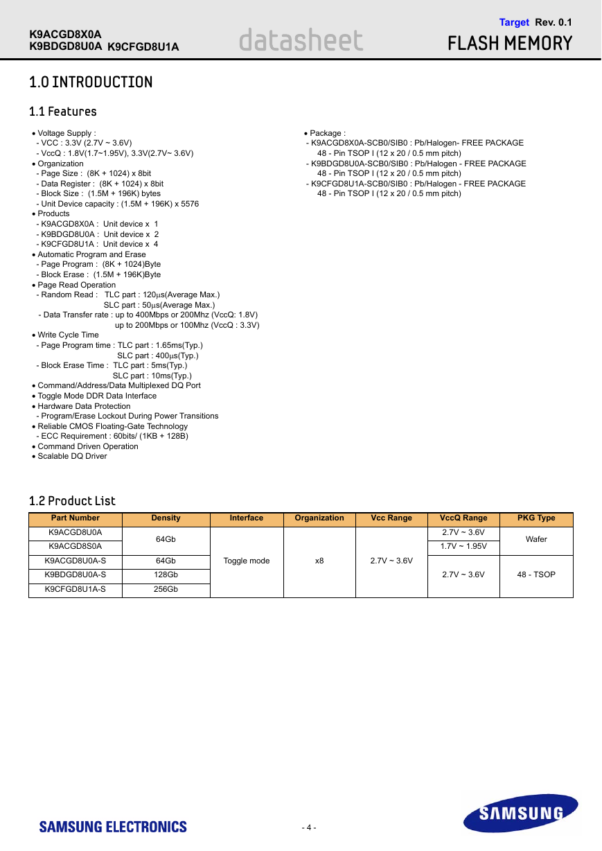
K9ACGD8X0A K9BDGD8U0A K9CFGD8U1A datasheet Target Rev. 0.1 FLASH MEMORY  Package : - K9ACGD8X0A-SCB0/SIB0 : Pb/Halogen- FREE PACKAGE 48 - Pin TSOP I (12 x 20 / 0.5 mm pitch) - K9BDGD8U0A-SCB0/SIB0 : Pb/Halogen - FREE PACKAGE 48 - Pin TSOP I (12 x 20 / 0.5 mm pitch) - K9CFGD8U1A-SCB0/SIB0 : Pb/Halogen - FREE PACKAGE 48 - Pin TSOP I (12 x 20 / 0.5 mm pitch) 1.0 INTRODUCTION 1.1 Features  Voltage Supply : - VCC : 3.3V (2.7V ~ 3.6V) - VccQ : 1.8V(1.7~1.95V), 3.3V(2.7V~ 3.6V)  Organization - Page Size : (8K + 1024) x 8bit - Data Register : (8K + 1024) x 8bit - Block Size : (1.5M + 196K) bytes - Unit Device capacity : (1.5M + 196K) x 5576  Products - K9ACGD8X0A : Unit device x 1 - K9BDGD8U0A : Unit device x 2 - K9CFGD8U1A : Unit device x 4  Automatic Program and Erase - Page Program : (8K + 1024)Byte - Block Erase : (1.5M + 196K)Byte  Page Read Operation - Random Read : TLC part : 120s(Average Max.) SLC part : 50s(Average Max.) - Data Transfer rate : up to 400Mbps or 200Mhz (VccQ: 1.8V) up to 200Mbps or 100Mhz (VccQ : 3.3V)  Write Cycle Time - Page Program time : TLC part : 1.65ms(Typ.) SLC part : 400s(Typ.) - Block Erase Time : TLC part : 5ms(Typ.) SLC part : 10ms(Typ.)  Command/Address/Data Multiplexed DQ Port  Toggle Mode DDR Data Interface  Hardware Data Protection - Program/Erase Lockout During Power Transitions  Reliable CMOS Floating-Gate Technology - ECC Requirement : 60bits/ (1KB + 128B)  Command Driven Operation  Scalable DQ Driver 1.2 Product List Part Number K9ACGD8U0A K9ACGD8S0A K9ACGD8U0A-S K9BDGD8U0A-S K9CFGD8U1A-S Density Interface Organization Vcc Range 64Gb 64Gb 128Gb 256Gb Toggle mode x8 2.7V ~ 3.6V VccQ Range 2.7V ~ 3.6V 1.7V ~ 1.95V PKG Type Wafer 2.7V ~ 3.6V 48 - TSOP - 4 -
K9ACGD8X0A K9BDGD8U0A K9CFGD8U1A datasheet Target Rev. 0.1 FLASH MEMORY 1.3 General Description Toggle DDR is a NAND interface for high performance applications which support data read and write operations using bidirectional DQS. Toggle DDR NAND has implemented ’Double Data Rate’ without a clock. It is compatible with functions and command which have been supported in con- ventional type NAND(i.e. SDR NAND) while providing high data transfer rate based on the high-speed Toggle DDR Interface and saving power with sep- arated DQ voltage. For applications that require high capacity and high performance NAND, Toggle DDR NAND is the most appropriate. Toggle DDR2.0 NAND supports the interface speed of up to 200 MHz(400 Mbps), which is more than 10 times faster than the data transfer rate offered by SDR NAND (40Mbps). Toggle DDR NAND transfers data at high speed using DQS signal that behaves as a clock, and DQS shall be used only when data is transferred for optimal power consumption. 1.4 Toggle DDR Interface according to Data Transfer Rate Feature VccQ CMOS Vref Support I/O Type Differential signaling for DQS and RE Note1) NOTE : 1) Vref shall be used for DQx when differential signaling is used. up to 200Mbps (100Mhz) 200Mbps to 400Mbps (200Mhz) 3.3V Support Support Support 1.8V only Not support Support Support - 5 -
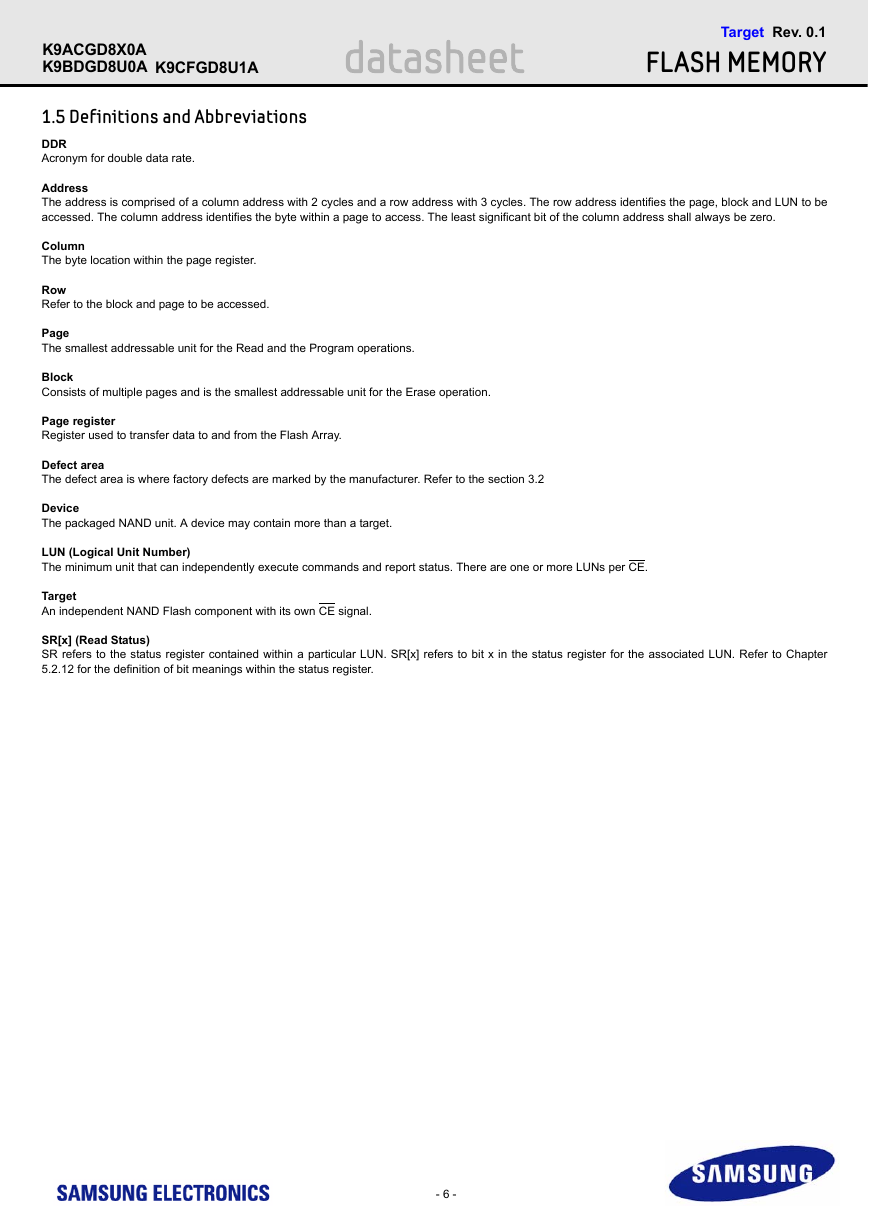
K9ACGD8X0A K9BDGD8U0A K9CFGD8U1A datasheet Target Rev. 0.1 FLASH MEMORY 1.5 Definitions and Abbreviations DDR Acronym for double data rate. Address The address is comprised of a column address with 2 cycles and a row address with 3 cycles. The row address identifies the page, block and LUN to be accessed. The column address identifies the byte within a page to access. The least significant bit of the column address shall always be zero. Column The byte location within the page register. Row Refer to the block and page to be accessed. Page The smallest addressable unit for the Read and the Program operations. Block Consists of multiple pages and is the smallest addressable unit for the Erase operation. Page register Register used to transfer data to and from the Flash Array. Defect area The defect area is where factory defects are marked by the manufacturer. Refer to the section 3.2 Device The packaged NAND unit. A device may contain more than a target. LUN (Logical Unit Number) The minimum unit that can independently execute commands and report status. There are one or more LUNs per CE. Target An independent NAND Flash component with its own CE signal. SR[x] (Read Status) SR refers to the status register contained within a particular LUN. SR[x] refers to bit x in the status register for the associated LUN. Refer to Chapter 5.2.12 for the definition of bit meanings within the status register. - 6 -
分享到:
收藏