Microstrip Filters for RF/Microwave Applications. Jia-Sheng Hong, M. J. Lancaster
Copyright © 2001 John Wiley & Sons, Inc.
ISBNs: 0-471-38877-7 (Hardback); 0-471-22161-9 (Electronic)
Microstrip Filters
for RF/Microwave
Applications
�
Microstrip Filters
for RF/Microwave
Applications
JIA-SHENG HONG
M. J. LANCASTER
A WILEY-INTERSCIENCE PUBLICATION
JOHN WILEY & SONS, INC.
NEW YORK / CHICHESTER / WEINHEIM / BRISBANE / SINGAPORE / TORONTO
�
Designations used by companies to distinguish their products are often claimed as trademarks. In all instances
where John Wiley & Sons, Inc., is aware of a claim, the product names appear in initial capital or ALL CAPITAL
LETTERS. Readers, however, should contact the appropriate companies for more complete information regarding
trademarks and registration.
Copyright © 2001 by John Wiley & Sons, Inc. All rights reserved.
No part of this publication may be reproduced, stored in a retrieval system or transmitted in any form or by any means, electronic
or mechanical, including uploading, downloading, printing, decompiling, recording or otherwise, except as permitted under
Sections 107 or 108 of the 1976 United States Copyright Act, without the prior written permission of the Publisher. Requests to
the Publisher for permission should be addressed to the Permissions Department, John Wiley & Sons, Inc., 605 Third Avenue,
New York, NY 10158-0012, (212) 850-6011, fax (212) 850-6008, E-Mail: PERMREQ @ WILEY.COM.
This publication is designed to provide accurate and authoritative information in regard to the
subject matter covered. It is sold with the understanding that the publisher is not engaged in
rendering professional services. If professional advice or other expert assistance is required, the
services of a competent professional person should be sought.
ISBN 0-471-22161-9
This title is also available in print as ISBN 0-471-38877-7.
For more information about Wiley products, visit our web site at www.Wiley.com.
�
Contents
Preface
1. Introduction
2. Network Analysis
2.1 Network Variables
2.2 Scattering Parameters
2.3 Short-Circuit Admittance Parameters
2.4 Open-Circuit Impedance Parameters
2.5 ABCD Parameters
2.6 Transmission Line Networks
2.7 Network Connections
2.8 Network Parameter Conversions
2.9 Symmetrical Network Analysis
2.10 Multi-Port Networks
2.11 Equivalent and Dual Networks
2.12 Multi-Mode Networks
References
3. Basic Concepts and Theories of Filters
3.1 Transfer Functions
3.1.1 General Definitions
3.1.2 The Poles and Zeros on the Complex Plane
3.1.3 Butterworth (Maximally Flat) Response
3.1.4 Chebyshev Response
3.1.5 Elliptic Function Response
3.1.6 Gaussian (Maximally Flat Group-Delay) Response
xi
1
7
7
8
11
11
12
12
14
17
18
21
24
26
28
29
29
29
30
31
32
34
36
v
�
vi
CONTENTS
3.1.7 All-Pass Response
3.2 Lowpass Prototype Filters and Elements
3.2.1 Butterworth Lowpass Prototype Filters
3.2.2 Chebyshev Lowpass Prototype Filters
3.2.3 Elliptic Function Lowpass Prototype Filters
3.2.4 Gaussian Lowpass Prototype Filters
3.2.5 All-Pass Lowpass Prototype Filters
3.3 Frequency and Element Transformations
3.3.1 Lowpass Transformation
3.3.2 Highpass Transformation
3.3.3 Bandpass Transformation
3.3.4 Bandstop Transformation
3.4 Immittance Inverters
3.4.1 Definition of Immittance, Impedance and Admittance Inverters
3.4.2 Filters with Immittance Inverters
3.4.3 Practical Realization of Immittance Inverters
3.5 Richards’ Transformation and Kuroda Identities
3.5.1 Richards’ Transformation
3.5.2 Kuroda Identities
3.5.3 Coupled-Line Equivalent Circuits
3.6 Dissipation and Unloaded Quality Factor
3.6.1 Unloaded Quality Factors of Lossy Reactive Elements
3.6.2 Dissipation Effects on Lowpass and Highpass Filters
3.6.3 Dissipation Effects on Bandpass and Bandstop Filters
References
4. Transmission Lines and Components
4.1 Microstrip Lines
4.1.1 Microstrip Structure
4.1.2 Waves in Microstrip
4.1.3 Quasi-TEM Approximation
4.1.4 Effective Dielectric Constant and Characteristic Impedance
4.1.5 Guided Wavelength, Propagation Constant, Phase
4.1.5 Velocity, and Electrical Length
4.1.6 Synthesis of W/h
4.1.7 Effect of Strip Thickness
4.1.8 Dispersion in Microstrip
4.1.9 Microstrip Losses
4.1.10 Effect of Enclosure
4.1.11 Surface Waves and Higher-Order Modes
4.2 Coupled Lines
4.2.1 Even- and Odd-Mode Capacitances
4.2.2 Even- and Odd-Mode Characteristic Impedances and Effective
4.1.5 Dielectric Constants
4.2.3 More Accurate Design Equations
37
38
41
41
44
46
47
48
49
51
51
53
54
54
56
60
61
61
66
66
69
70
71
73
75
77
77
77
77
78
78
80
80
81
82
83
84
84
84
85
87
87
�
CONTENTS
vii
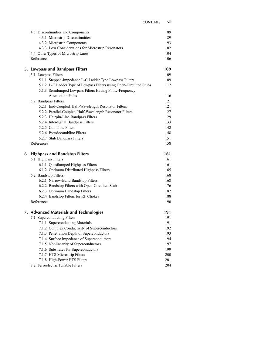
4.3 Discontinuities and Components
4.3.1 Microstrip Discontinuities
4.3.2 Microstrip Components
4.3.3 Loss Considerations for Microstrip Resonators
4.4 Other Types of Microstrip Lines
References
5. Lowpass and Bandpass Filters
5.1 Lowpass Filters
5.1.1 Stepped-Impedance L-C Ladder Type Lowpass Filters
5.1.2 L-C Ladder Type of Lowpass Filters using Open-Circuited Stubs
5.1.3 Semilumped Lowpass Filters Having Finite-Frequency
5.1.3 Attenuation Poles
5.2 Bandpass Filters
5.2.1 End-Coupled, Half-Wavelength Resonator Filters
5.2.2 Parallel-Coupled, Half-Wavelength Resonator Filters
5.2.3 Hairpin-Line Bandpass Filters
5.2.4 Interdigital Bandpass Filters
5.2.5 Combline Filters
5.2.6 Pseudocombline Filters
5.2.7 Stub Bandpass Filters
References
6. Highpass and Bandstop Filters
6.1 Highpass Filters
6.1.1 Quasilumped Highpass Filters
6.1.2 Optimum Distributed Highpass Filters
6.2 Bandstop Filters
6.2.1 Narrow-Band Bandstop Filters
6.2.2 Bandstop Filters with Open-Circuited Stubs
6.2.3 Optimum Bandstop Filters
6.2.4 Bandstop Filters for RF Chokes
References
7. Advanced Materials and Technologies
7.1 Superconducting Filters
7.1.1 Superconducting Materials
7.1.2 Complex Conductivity of Superconductors
7.1.3 Penetration Depth of Superconductors
7.1.4 Surface Impedance of Superconductors
7.1.5 Nonlinearity of Superconductors
7.1.6 Substrates for Superconductors
7.1.7 HTS Microstrip Filters
7.1.8 High-Power HTS Filters
7.2 Ferroelectric Tunable Filters
89
89
93
102
104
106
109
109
109
112
116
121
121
127
129
133
142
148
151
158
161
161
161
165
168
168
176
182
188
190
191
191
191
192
193
194
197
199
200
201
204
�
viii
CONTENTS
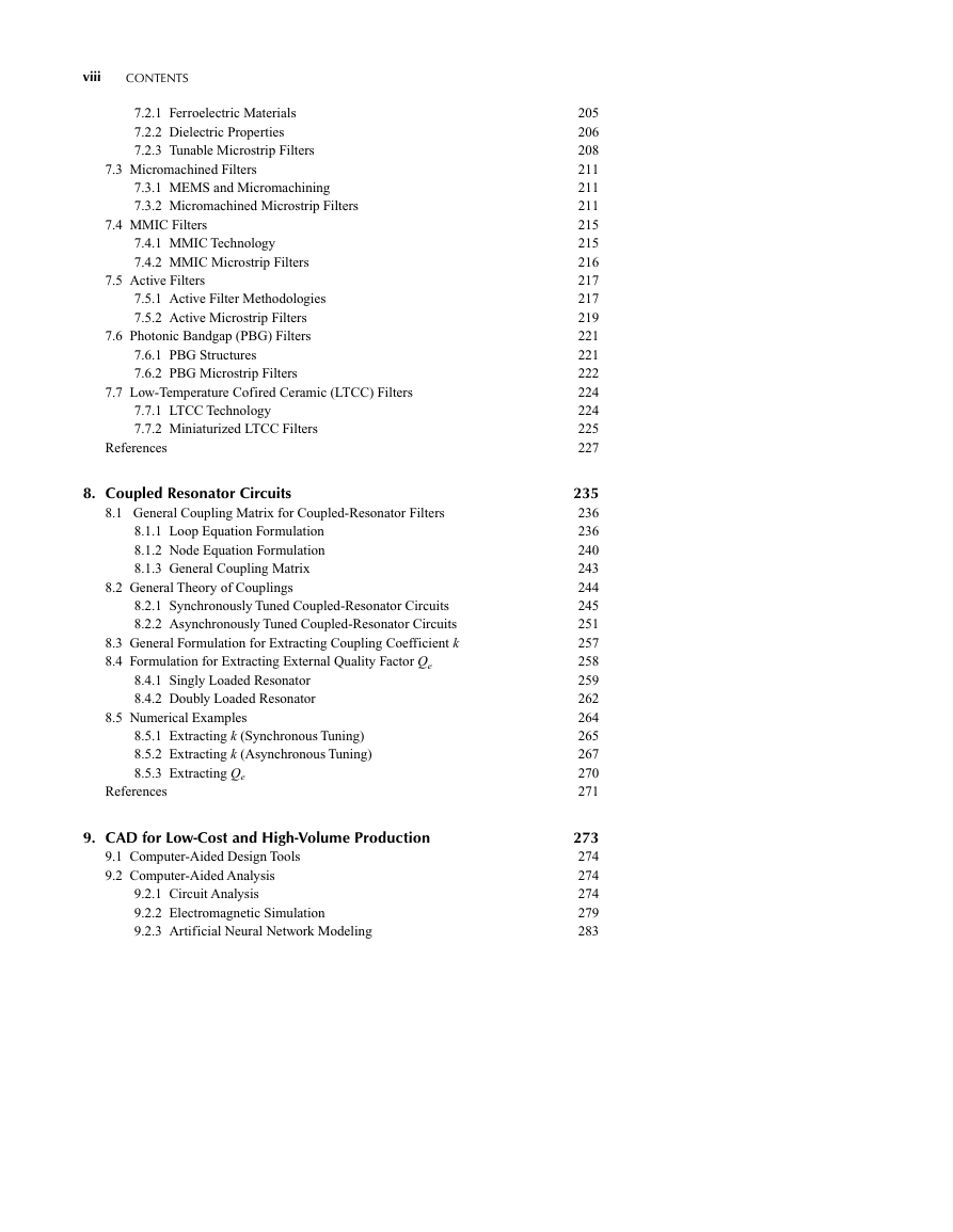
7.2.1 Ferroelectric Materials
7.2.2 Dielectric Properties
7.2.3 Tunable Microstrip Filters
7.3 Micromachined Filters
7.3.1 MEMS and Micromachining
7.3.2 Micromachined Microstrip Filters
7.4 MMIC Filters
7.4.1 MMIC Technology
7.4.2 MMIC Microstrip Filters
7.5 Active Filters
7.5.1 Active Filter Methodologies
7.5.2 Active Microstrip Filters
7.6 Photonic Bandgap (PBG) Filters
7.6.1 PBG Structures
7.6.2 PBG Microstrip Filters
7.7 Low-Temperature Cofired Ceramic (LTCC) Filters
7.7.1 LTCC Technology
7.7.2 Miniaturized LTCC Filters
References
8. Coupled Resonator Circuits
8.1 General Coupling Matrix for Coupled-Resonator Filters
8.1.1 Loop Equation Formulation
8.1.2 Node Equation Formulation
8.1.3 General Coupling Matrix
8.2 General Theory of Couplings
8.2.1 Synchronously Tuned Coupled-Resonator Circuits
8.2.2 Asynchronously Tuned Coupled-Resonator Circuits
8.3 General Formulation for Extracting Coupling Coefficient k
8.4 Formulation for Extracting External Quality Factor Qe
8.4.1 Singly Loaded Resonator
8.4.2 Doubly Loaded Resonator
8.5 Numerical Examples
8.5.1 Extracting k (Synchronous Tuning)
8.5.2 Extracting k (Asynchronous Tuning)
8.5.3 Extracting Qe
References
9. CAD for Low-Cost and High-Volume Production
9.1 Computer-Aided Design Tools
9.2 Computer-Aided Analysis
9.2.1 Circuit Analysis
9.2.2 Electromagnetic Simulation
9.2.3 Artificial Neural Network Modeling
205
206
208
211
211
211
215
215
216
217
217
219
221
221
222
224
224
225
227
235
236
236
240
243
244
245
251
257
258
259
262
264
265
267
270
271
273
274
274
274
279
283
�
CONTENTS
ix
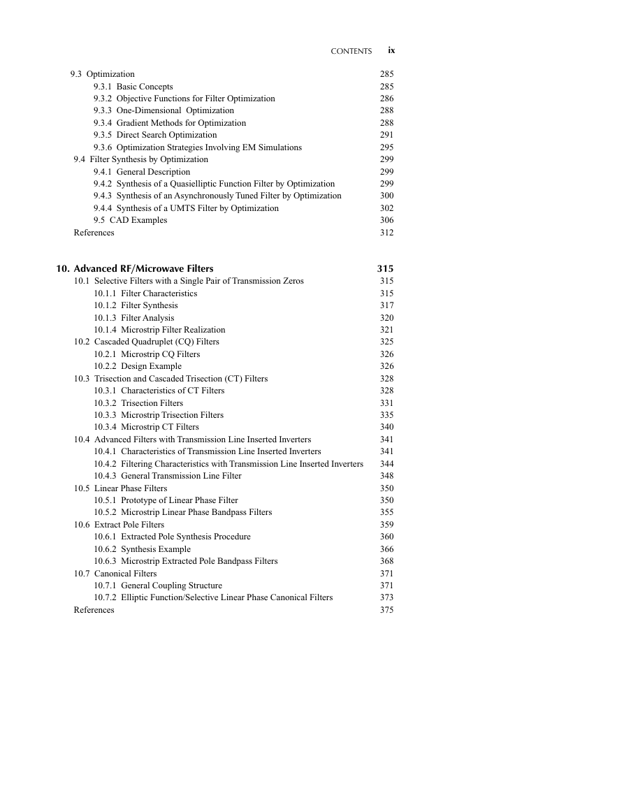
9.3 Optimization
9.3.1 Basic Concepts
9.3.2 Objective Functions for Filter Optimization
9.3.3 One-Dimensional Optimization
9.3.4 Gradient Methods for Optimization
9.3.5 Direct Search Optimization
9.3.6 Optimization Strategies Involving EM Simulations
9.4 Filter Synthesis by Optimization
9.4.1 General Description
9.4.2 Synthesis of a Quasielliptic Function Filter by Optimization
9.4.3 Synthesis of an Asynchronously Tuned Filter by Optimization
9.4.4 Synthesis of a UMTS Filter by Optimization
9.5 CAD Examples
References
10. Advanced RF/Microwave Filters
10.1 Selective Filters with a Single Pair of Transmission Zeros
10.1.1 Filter Characteristics
10.1.2 Filter Synthesis
10.1.3 Filter Analysis
10.1.4 Microstrip Filter Realization
10.2 Cascaded Quadruplet (CQ) Filters
10.2.1 Microstrip CQ Filters
10.2.2 Design Example
10.3 Trisection and Cascaded Trisection (CT) Filters
10.3.1 Characteristics of CT Filters
10.3.2 Trisection Filters
10.3.3 Microstrip Trisection Filters
10.3.4 Microstrip CT Filters
10.4 Advanced Filters with Transmission Line Inserted Inverters
10.4.1 Characteristics of Transmission Line Inserted Inverters
10.4.2 Filtering Characteristics with Transmission Line Inserted Inverters
10.4.3 General Transmission Line Filter
10.5 Linear Phase Filters
10.5.1 Prototype of Linear Phase Filter
10.5.2 Microstrip Linear Phase Bandpass Filters
10.6 Extract Pole Filters
10.6.1 Extracted Pole Synthesis Procedure
10.6.2 Synthesis Example
10.6.3 Microstrip Extracted Pole Bandpass Filters
10.7 Canonical Filters
10.7.1 General Coupling Structure
10.7.2 Elliptic Function/Selective Linear Phase Canonical Filters
References
285
285
286
288
288
291
295
299
299
299
300
302
306
312
315
315
315
317
320
321
325
326
326
328
328
331
335
340
341
341
344
348
350
350
355
359
360
366
368
371
371
373
375
�



 2023年江西萍乡中考道德与法治真题及答案.doc
 2012年重庆南川中考生物真题及答案.doc
 2013年江西师范大学地理学综合及文艺理论基础考研真题.doc
 2020年四川甘孜小升初语文真题及答案I卷.doc
 2020年注册岩土工程师专业基础考试真题及答案.doc
 2023-2024学年福建省厦门市九年级上学期数学月考试题及答案.doc
 2021-2022学年辽宁省沈阳市大东区九年级上学期语文期末试题及答案.doc
 2022-2023学年北京东城区初三第一学期物理期末试卷及答案.doc
 2018上半年江西教师资格初中地理学科知识与教学能力真题及答案.doc
 2012年河北国家公务员申论考试真题及答案-省级.doc
 2020-2021学年江苏省扬州市江都区邵樊片九年级上学期数学第一次质量检测试题及答案.doc
 2022下半年黑龙江教师资格证中学综合素质真题及答案.doc