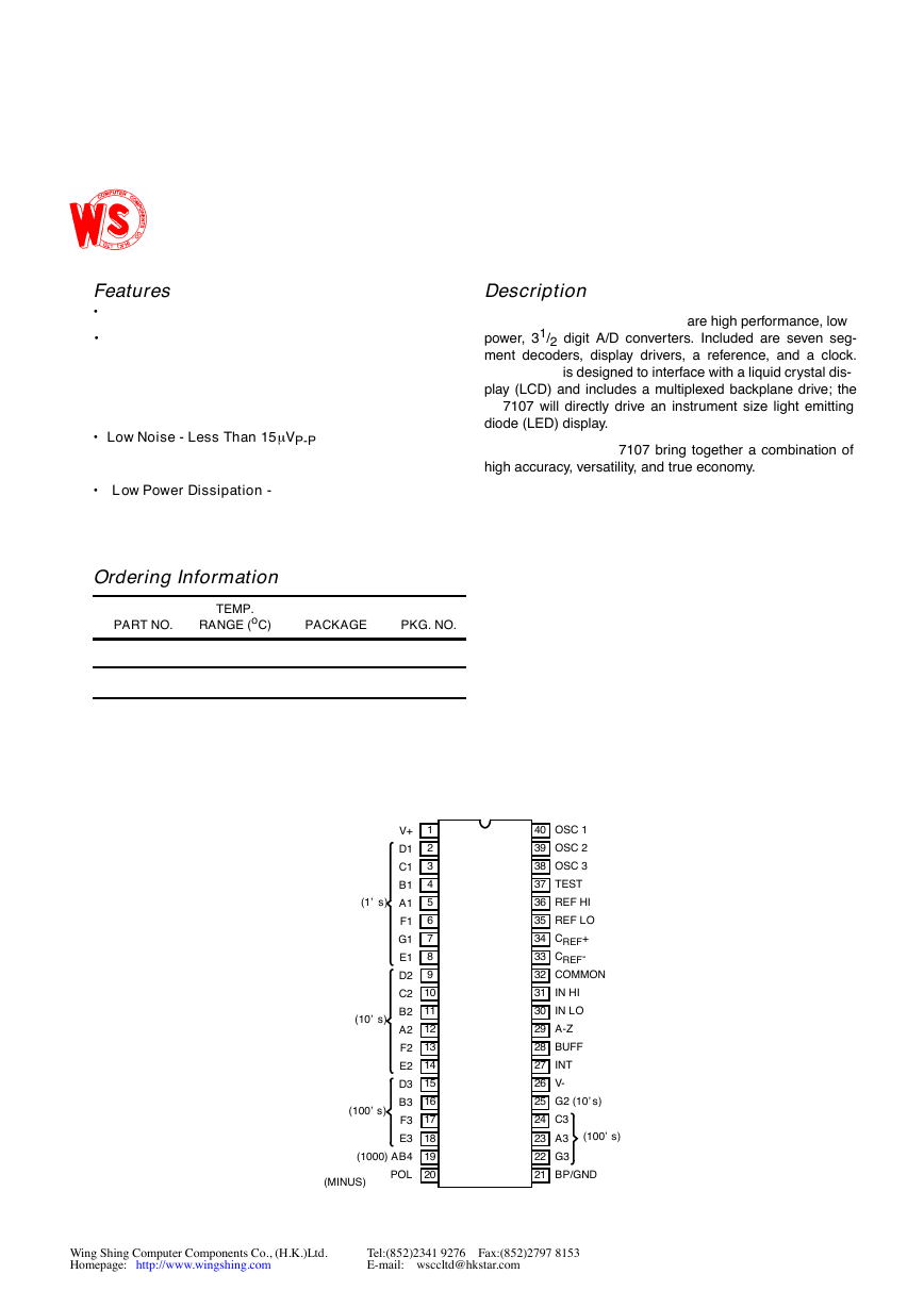
Features•••Low Noise - Less Than 15mVP-P•Low Power Dissipation - Descriptionarehighperformance,lowpower,31/2digitA/Dconverters.Includedaresevenseg-mentdecoders,displaydrivers,areference,andaclock.isdesignedtointerfacewithaliquidcrystaldis-play(LCD)andincludesamultiplexedbackplanedrive;the7107willdirectlydriveaninstrumentsizelightemittingdiode (LED) display.7107bringtogetheracombinationofhighaccuracy,versatility,andtrueeconomy.Ordering InformationPART NO.TEMP.RANGE (oC)PACKAGEPKG. NO.1312345678910111214151617181920V+D1C1B1A1F1G1E1D2C2B2A2F2E2D3B3F3E3(1000) AB4POL2840393837363534333231302927262524232221OSC 1OSC 2OSC 3TESTREF HIREF LOCREF+CREF-COMMONIN HIIN LOA-ZBUFFINTV-G2 (10’s)C3A3G3BP/GND(1’s)(10’s)(100’s)(MINUS)(100’s)Wing Shing Computer Components Co., (H.K.)Ltd.Tel:(852)2341 9276 Fax:(852)2797 8153Homepage:http://www.wingshing.comE-mail: wsccltd@hkstar.com�
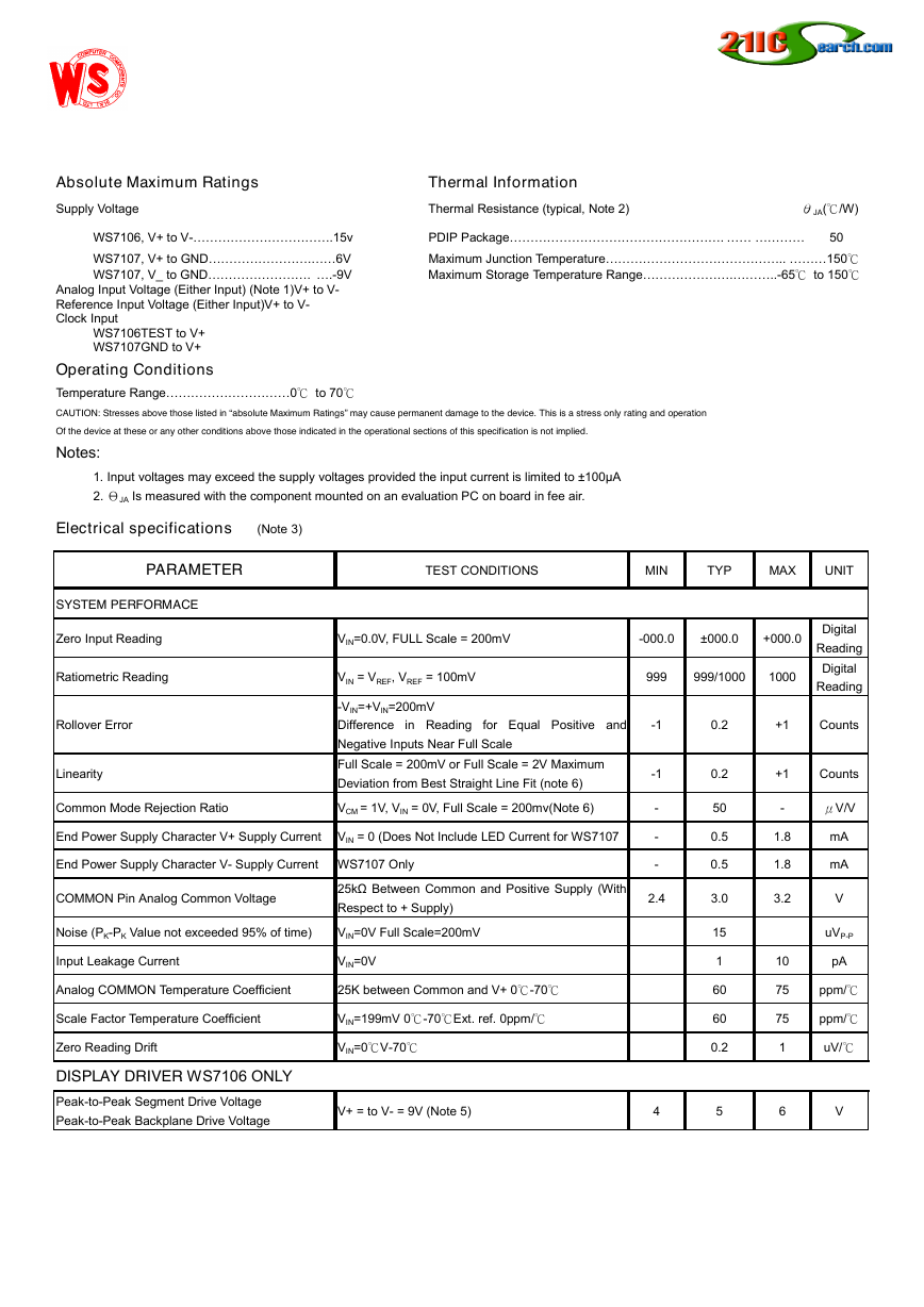
Absolute Maximum Ratings Thermal InformationSupply VoltageThermal Resistance (typical, Note 2)θJA(℃/W)WS7106, V+ to V-.15vPDIP Package. 50WS7107, V+ to GND.6VMaximum Junction Temperature.. 150℃WS7107, V_ to GND..-9VMaximum Storage Temperature Range...-65℃ to 150℃Analog Input Voltage (Either Input) (Note 1)V+ to V-Reference Input Voltage (Either Input)V+ to V-Clock InputWS7106TEST to V+WS7107GND to V+Operating ConditionsTemperature Range0℃ to 70℃CAUTION: Stresses above those listed in “absolute Maximum Ratings” may cause permanent damage to the device. This is a stress only rating and operationOf the device at these or any other conditions above those indicated in the operational sections of this specification is not implied.Notes:1. Input voltages may exceed the supply voltages provided the input current is limited to –100A2. ΘJA Is measured with the component mounted on an evaluation PC on board in fee air.Electrical specifications (Note 3)PARAMETERTEST CONDITIONSMINTYPMAXUNITSYSTEM PERFORMACEZero Input ReadingVIN=0.0V, FULL Scale = 200mV-000.0–000.0+000.0DigitalReadingRatiometric ReadingVIN = VREF, VREF = 100mV999999/10001000DigitalReadingRollover Error-VIN=+VIN=200mVDifference in Reading for Equal Positive andNegative Inputs Near Full Scale-10.2+1CountsLinearityFull Scale = 200mV or Full Scale = 2V MaximumDeviation from Best Straight Line Fit (note 6)-10.2+1CountsCommon Mode Rejection RatioVCM = 1V, VIN = 0V, Full Scale = 200mv(Note 6)-50-μV/VEnd Power Supply Character V+ Supply CurrentVIN = 0 (Does Not Include LED Current for WS7107-0.51.8mAEnd Power Supply Character V- Supply CurrentWS7107 Only-0.51.8mACOMMON Pin Analog Common Voltage25kΩ Between Common and Positive Supply (WithRespect to + Supply)2.43.03.2VNoise (PK-PK Value not exceeded 95% of time)VIN=0V Full Scale=200mV15uVP-PInput Leakage CurrentVIN=0V110pAAnalog COMMON Temperature Coefficient25K between Common and V+ 0℃-70℃6075ppm/℃Scale Factor Temperature CoefficientVIN=199mV 0℃-70℃Ext. ref. 0ppm/℃6075ppm/℃Zero Reading DriftVIN=0℃V-70℃0.21uV/℃DISPLAY DRIVER WS7106 ONLYPeak-to-Peak Segment Drive VoltagePeak-to-Peak Backplane Drive VoltageV+ = to V- = 9V (Note 5)456V�
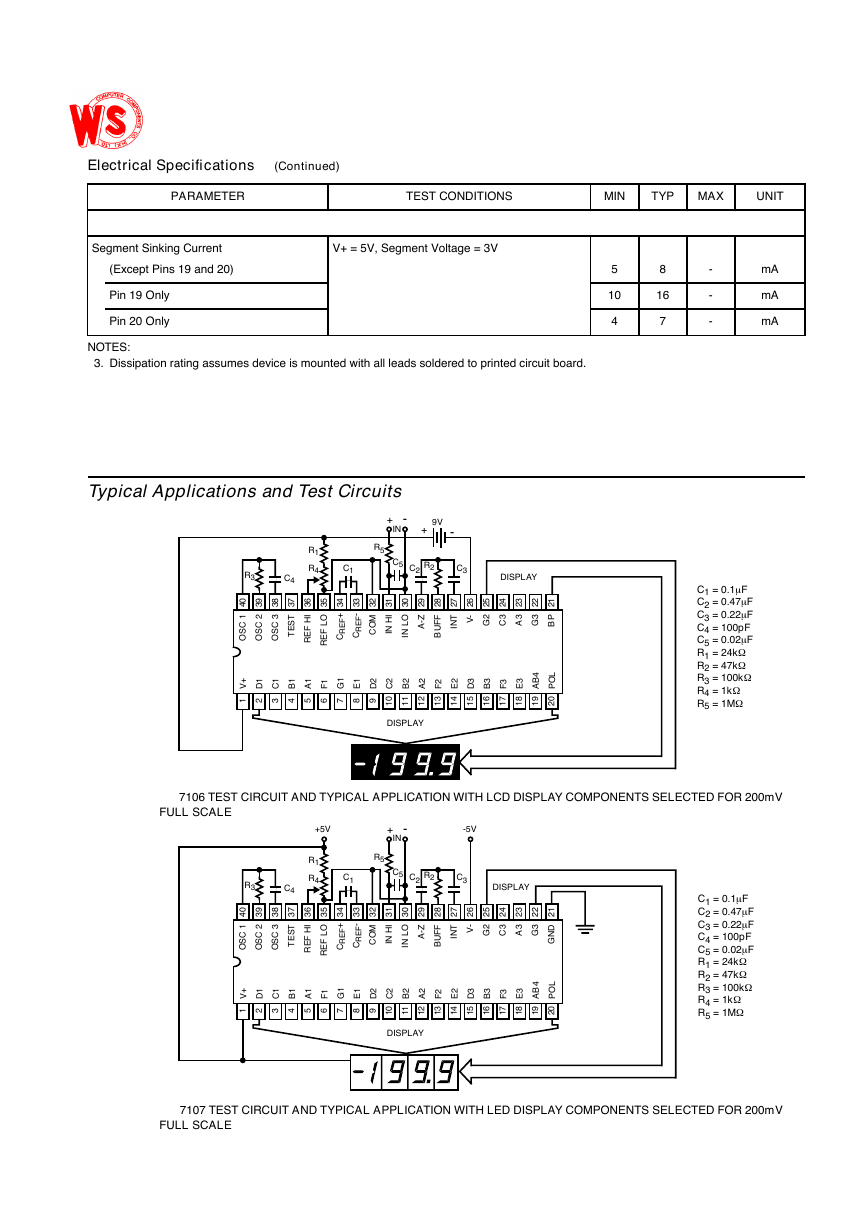
Typical Applications and Test CircuitsSegment Sinking CurrentV+ = 5V, Segment Voltage = 3V(Except Pins 19 and 20)58-mAPin 19 Only1016-mAPin 20 Only47-mANOTES:3.Dissipation rating assumes device is mounted with all leads soldered to printed circuit board.Electrical Specifications (Continued)PARAMETERTEST CONDITIONSMINTYPMAXUNIT7106TESTCIRCUITANDTYPICALAPPLICATIONWITHLCDDISPLAYCOMPONENTSSELECTEDFOR200mVFULL SCALE7107TESTCIRCUITANDTYPICALAPPLICATIONWITHLEDDISPLAYCOMPONENTSSELECTEDFOR200mVFULL SCALE13123456789101112141516171819202840393837363534333231302927262524232221V+D1C1B1A1F1G1E1D2C2B2A2F2E2D3B3F3E3AB4POLOSC 1OSC 2OSC 3TESTREF HIREF LOCREF+CREF-COMIN HIIN LOA-ZBUFFINTV-G2C3A3G3BPDISPLAYDISPLAYC1C2C3C4R3R1R4C5+-INR5R29VC1 = 0.1mFC2 = 0.47mFC3 = 0.22mFC4 = 100pFC5 = 0.02mFR1 = 24kWR2 = 47kWR3 = 100kWR4 = 1kWR5 = 1MW+-13123456789101112141516171819202840393837363534333231302927262524232221V+D1C1B1A1F1G1E1D2C2B2A2F2E2D3B3F3E3AB4POLOSC 1OSC 2OSC 3TESTREF HIREF LOCREF+CREF-COMIN HIIN LOA-ZBUFFINTV-G2C3A3G3GNDDISPLAYDISPLAYC1C2C3C4R3R1R4C5+-INR5R2+5V-5VC1 = 0.1mFC2 = 0.47mFC3 = 0.22mFC4 = 100pFC5 = 0.02mFR1 = 24kWR2 = 47kWR3 = 100kWR4 = 1kWR5 = 1MW�
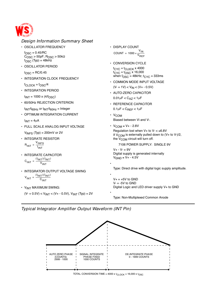
Typical Integrator Amplifier Output Waveform (INT Pin)Design Information Summary Sheet•OSCILLATOR FREQUENCYfOSC = 0.45/RCCOSC > 50pF; ROSC > 50kWfOSC (Typ) = 48kHz•OSCILLATOR PERIODtOSC = RC/0.45•INTEGRATION CLOCK FREQUENCYfCLOCK = fOSC/4•INTEGRATION PERIODtINT = 1000 x (4/fOSC)•60/50Hz REJECTION CRITERIONtINT/t60Hz or tlNT/t60Hz = Integer•OPTIMUM INTEGRATION CURRENTIINT = 4mA•FULL SCALE ANALOG INPUT VOLTAGEVlNFS (Typ) = 200mV or 2V•INTEGRATE RESISTOR•INTEGRATE CAPACITOR•INTEGRATOR OUTPUT VOLTAGE SWING•VINT MAXIMUM SWING:(V- + 0.5V) < VINT < (V+ - 0.5V), VINT (Typ) = 2V•DISPLAY COUNT•CONVERSION CYCLEtCYC = tCL0CK x 4000tCYC = tOSC x 16,000when fOSC = 48kHz; tCYC = 333ms•COMMON MODE INPUT VOLTAGE(V- + 1V) < VlN < (V+ - 0.5V)•AUTO-ZERO CAPACITOR0.01mF < CAZ < 1mF•REFERENCE CAPACITOR0.1mF < CREF < 1mF•VCOMBiased between Vi and V-.•VCOM@ V+ - 2.8VRegulation lost when V+ to V- <@6.8VIf VCOM is externally pulled down to (V+ to V-)/2,the VCOM circuit will turn off.7106 POWER SUPPLY:SINGLE 9VV+ - V- = 9VDigital supply is generated internallyVGND@ V+ - 4.5V•Type: Direct drive with digital logic supply amplitude.•V+ = +5V to GNDV- = -5V to GNDDigital Logic and LED driver supply V+ to GND•Type: Non-Multiplexed Common AnodeRINTVINFSIINT-----------------=CINTtINT()IINT()VINT--------------------------------=VINTtINT()IINT()CINT--------------------------------=COUNT1000VINVREF---------------·=AUTO ZERO PHASE(COUNTS)2999 - 1000SIGNAL INTEGRATEPHASE FIXED1000 COUNTSDE-INTEGRATE PHASE0 - 1999 COUNTSTOTAL CONVERSION TIME = 4000 x tCLOCK = 16,000 x tOSC�
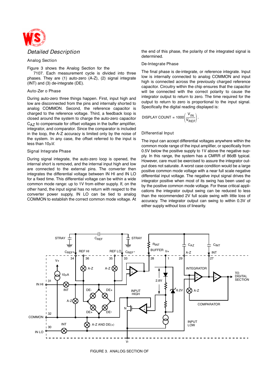
Detailed DescriptionAnalog SectionFigure3showstheAnalogSectionforthe7107.Eachmeasurementcycleisdividedintothreephases.Theyare(1)auto-zero(A-Z),(2)signalintegrate(INT) and (3) de-integrate (DE).Auto-Zero PhaseDuringauto-zerothreethingshappen.First,inputhighandlowaredisconnectedfromthepinsandinternallyshortedtoanalogCOMMON.Second,thereferencecapacitorischargedtothereferencevoltage.Third,afeedbackloopisclosedaroundthesystemtochargetheauto-zerocapacitorCAZtocompensateforoffsetvoltagesinthebufferamplifier,integrator,andcomparator.Sincethecomparatorisincludedintheloop,theA-Zaccuracyislimitedonlybythenoiseofthesystem.Inanycase,theoffsetreferredtotheinputisless than 10mV.Signal Integrate PhaseDuringsignalintegrate,theauto-zeroloopisopened,theinternalshortisremoved,andtheinternalinputhighandlowareconnectedtotheexternalpins.TheconverterthenintegratesthedifferentialvoltagebetweenINHIandINLOforafixedtime.Thisdifferentialvoltagecanbewithinawidecommonmoderange:upto1Vfromeithersupply.If,ontheotherhand,theinputsignalhasnoreturnwithrespecttotheconverterpowersupply,INLOcanbetiedtoanalogCOMMONtoestablishthecorrectcommonmodevoltage.Attheendofthisphase,thepolarityoftheintegratedsignalisdetermined.De-Integrate PhaseThefinalphaseisde-integrate,orreferenceintegrate.InputlowisinternallyconnectedtoanalogCOMMONandinputhighisconnectedacrossthepreviouslychargedreferencecapacitor.Circuitrywithinthechipensuresthatthecapacitorwillbeconnectedwiththecorrectpolaritytocausetheintegratoroutputtoreturntozero.Thetimerequiredfortheoutputtoreturntozeroisproportionaltotheinputsignal.Specifically the digital reading displayed is:.Differential InputTheinputcanacceptdifferentialvoltagesanywherewithinthecommonmoderangeoftheinputamplifier,orspecificallyfrom0.5Vbelowthepositivesupplyto1Vabovethenegativesup-ply.Inthisrange,thesystemhasaCMRRof86dBtypical.However,caremustbeexercisedtoassuretheintegratorout-putdoesnotsaturate.Aworstcaseconditionwouldbealargepositivecommonmodevoltagewithanearfullscalenegativedifferentialinputvoltage.Thenegativeinputsignaldrivestheintegratorpositivewhenmostofitsswinghasbeenusedupbythepositivecommonmodevoltage.Forthesecriticalappli-cationstheintegratoroutputswingcanbereducedtolessthantherecommended2Vfullscaleswingwithlittlelossofaccuracy.Theintegratoroutputcanswingtowithin0.3Vofeither supply without loss oflinearity.DISPLAYCOUNT=1000VINVREF---------------ŁłFIGURE 3.ANALOG SECTION OFDE-DE+CINTCAZRINTBUFFERA-ZINT-+A-ZCOMPARATORIN HICOMMONIN LO313230DE-DE+INTA-Z34CREF+36REF HICREFREF LO35A-ZA-Z33CREF-282927TODIGITALSECTIONA-Z AND DE(–)INTEGRATORINTSTRAYSTRAYV+10mAV-NINPUTHIGH2.8V6.2VV+1INPUTLOW-+-+-+�
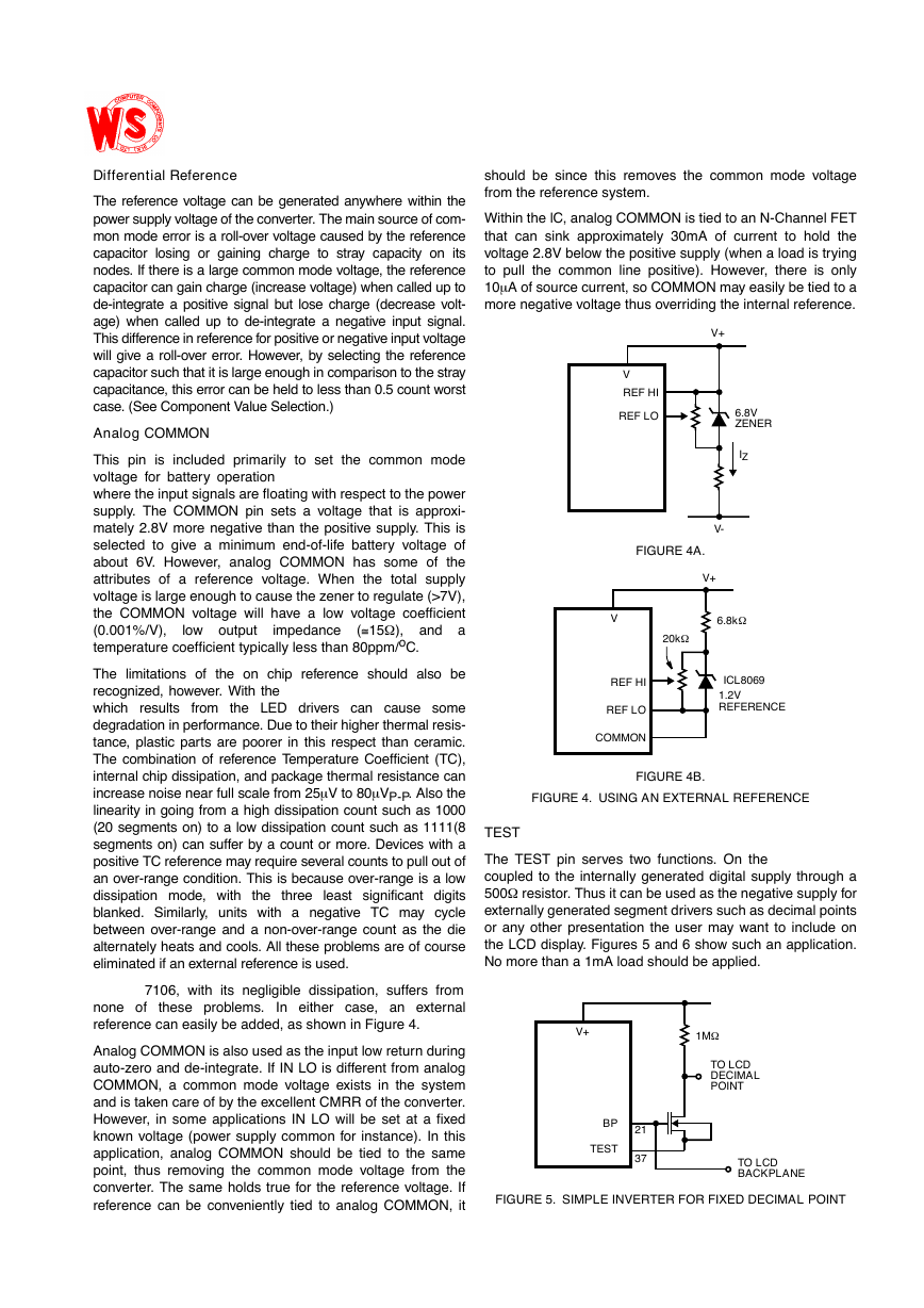
Differential ReferenceThereferencevoltagecanbegeneratedanywherewithinthepowersupplyvoltageoftheconverter.Themainsourceofcom-monmodeerrorisaroll-overvoltagecausedbythereferencecapacitorlosingorgainingchargetostraycapacityonitsnodes.Ifthereisalargecommonmodevoltage,thereferencecapacitorcangaincharge(increasevoltage)whencalleduptode-integrateapositivesignalbutlosecharge(decreasevolt-age)whencalleduptode-integrateanegativeinputsignal.Thisdifferenceinreferenceforpositiveornegativeinputvoltagewillgivearoll-overerror.However,byselectingthereferencecapacitorsuchthatitislargeenoughincomparisontothestraycapacitance,thiserrorcanbeheldtolessthan0.5countworstcase. (See Component Value Selection.)Analog COMMONThispinisincludedprimarilytosetthecommonmodevoltageforbatteryoperationwheretheinputsignalsarefloatingwithrespecttothepowersupply.TheCOMMONpinsetsavoltagethatisapproxi-mately2.8Vmorenegativethanthepositivesupply.Thisisselectedtogiveaminimumend-of-lifebatteryvoltageofabout6V.However,analogCOMMONhassomeoftheattributesofareferencevoltage.Whenthetotalsupplyvoltageislargeenoughtocausethezenertoregulate(>7V),theCOMMONvoltagewillhavealowvoltagecoefficient(0.001%/V),lowoutputimpedance(@15W),andatemperature coefficient typically less than 80ppm/oC.Thelimitationsoftheonchipreferenceshouldalsoberecognized,however.WiththewhichresultsfromtheLEDdriverscancausesomedegradationinperformance.Duetotheirhigherthermalresis-tance,plasticpartsarepoorerinthisrespectthanceramic.ThecombinationofreferenceTemperatureCoefficient(TC),internalchipdissipation,andpackagethermalresistancecanincreasenoisenearfullscalefrom25mVto80mVP-P.Alsothelinearityingoingfromahighdissipationcountsuchas1000(20segmentson)toalowdissipationcountsuchas1111(8segmentson)cansufferbyacountormore.DeviceswithapositiveTCreferencemayrequireseveralcountstopulloutofanover-rangecondition.Thisisbecauseover-rangeisalowdissipationmode,withthethreeleastsignificantdigitsblanked.Similarly,unitswithanegativeTCmaycyclebetweenover-rangeandanon-over-rangecountasthediealternatelyheatsandcools.Alltheseproblemsareofcourseeliminated if an external reference is used.7106,withitsnegligibledissipation,suffersfromnoneoftheseproblems.Ineithercase,anexternalreference can easily be added, as shown in Figure 4.AnalogCOMMONisalsousedastheinputlowreturnduringauto-zeroandde-integrate.IfINLOisdifferentfromanalogCOMMON,acommonmodevoltageexistsinthesystemandistakencareofbytheexcellentCMRRoftheconverter.However,insomeapplicationsINLOwillbesetatafixedknownvoltage(powersupplycommonforinstance).Inthisapplication,analogCOMMONshouldbetiedtothesamepoint,thusremovingthecommonmodevoltagefromtheconverter.Thesameholdstrueforthereferencevoltage.IfreferencecanbeconvenientlytiedtoanalogCOMMON,itshouldbesincethisremovesthecommonmodevoltagefrom the reference system.WithinthelC,analogCOMMONistiedtoanN-ChannelFETthatcansinkapproximately30mAofcurrenttoholdthevoltage2.8Vbelowthepositivesupply(whenaloadistryingtopullthecommonlinepositive).However,thereisonly10mAofsourcecurrent,soCOMMONmayeasilybetiedtoamore negative voltage thus overriding the internal reference.TESTTheTESTpinservestwofunctions.Onthecoupledtotheinternallygenerateddigitalsupplythrougha500Wresistor.ThusitcanbeusedasthenegativesupplyforexternallygeneratedsegmentdriverssuchasdecimalpointsoranyotherpresentationtheusermaywanttoincludeontheLCDdisplay.Figures5and6showsuchanapplication.No more than a 1mA load should be applied.FIGURE 4A.FIGURE 4B.FIGURE 4.USING AN EXTERNAL REFERENCEVREF LOREF HIV+V-6.8VZENERIZVREF HIREF LOCOMMONV+ICL80691.2VREFERENCE6.8kW20kWV+BPTEST2137TO LCDBACKPLANETO LCDDECIMALPOINT1MWFIGURE 5.SIMPLE INVERTER FOR FIXED DECIMAL POINT�
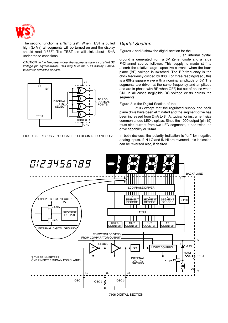
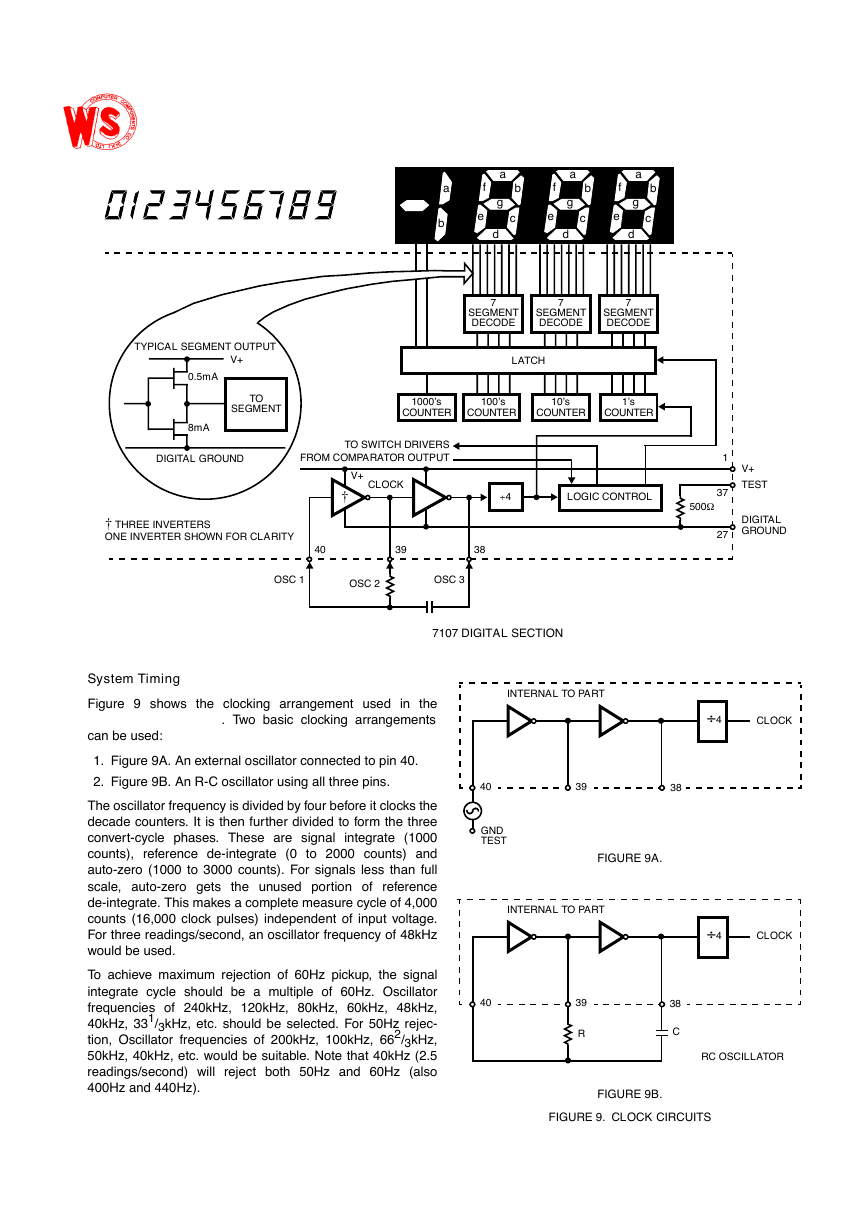
Thesecondfunctionisa“lamptest”.WhenTESTispulledhigh(toV+)allsegmentswillbeturnedonandthedisplayshouldread“1888”.TheTESTpinwillsinkabout15mAunder these conditions.CAUTION:Inthelamptestmode,thesegmentshaveaconstantDCvoltage(nosquare-wave).ThismayburntheLCDdisplayifmain-tained for extended periods.Digital SectionFigures7and8showthedigitalsectionforthe,aninternaldigitalgroundisgeneratedfroma6VZenerdiodeandalargeP-Channelsourcefollower.Thissupplyismadestifftoabsorbtherelativelargecapacitivecurrentswhenthebackplane(BP)voltageisswitched.TheBPfrequencyistheclockfrequencydividedby800.Forthreereadings/sec.,thisisa60Hzsquarewavewithanominalamplitudeof5V.ThesegmentsaredrivenatthesamefrequencyandamplitudeandareinphasewithBPwhenOFF,butoutofphasewhenON.InallcasesnegligibleDCvoltageexistsacrossthesegments.Figure8istheDigitalSectionofthe7106exceptthattheregulatedsupplyandbackplanedrivehavebeeneliminatedandthesegmentdrivehasbeenincreasedfrom2mAto8mA,typicalforinstrumentsizecommonanodeLEDdisplays.Sincethe1000output(pin19)mustsinkcurrentfromtwoLEDsegments,ithastwicethedrive capability or 16mA.Inbothdevices,thepolarityindicationis“on”fornegativeanaloginputs.IfINLOandINHIarereversed,thisindicationcan be reversed also, if desired.V+BPTESTDECIMALPOINTSELECTCD4030GNDV+TO LCDDECIMALPOINTSFIGURE 6.EXCLUSIVE ‘OR’ GATE FOR DECIMAL POINT DRIVE7SEGMENTDECODESEGMENTOUTPUT0.5mA2mAINTERNAL DIGITAL GROUNDTYPICAL SEGMENT OUTPUTV+LCD PHASE DRIVERLATCH7SEGMENTDECODE‚200LOGIC CONTROLINTERNALVTH = 1V7SEGMENTDECODE1000’s100’s10’s1’sTO SWITCH DRIVERSFROM COMPARATOR OUTPUTDIGITALGROUND‚4CLOCK403938OSC 1OSC 2OSC 3BACKPLANE21V+TESTV-500W37266.2VCOUNTERCOUNTERCOUNTERCOUNTER1cabcdfgeababcdfgeabcdfge†† THREE INVERTERSONE INVERTER SHOWN FOR CLARITY7106 DIGITAL SECTION�
System TimingFigure9showstheclockingarrangementusedinthe.Twobasicclockingarrangementscan be used:1.Figure 9A. An external oscillator connected to pin 40.2.Figure 9B. An R-C oscillator using all three pins.Theoscillatorfrequencyisdividedbyfourbeforeitclocksthedecadecounters.Itisthenfurtherdividedtoformthethreeconvert-cyclephases.Thesearesignalintegrate(1000counts),referencede-integrate(0to2000counts)andauto-zero(1000to3000counts).Forsignalslessthanfullscale,auto-zerogetstheunusedportionofreferencede-integrate.Thismakesacompletemeasurecycleof4,000counts(16,000clockpulses)independentofinputvoltage.Forthreereadings/second,anoscillatorfrequencyof48kHzwould be used.Toachievemaximumrejectionof60Hzpickup,thesignalintegratecycleshouldbeamultipleof60Hz.Oscillatorfrequenciesof240kHz,120kHz,80kHz,60kHz,48kHz,40kHz,331/3kHz,etc.shouldbeselected.For50Hzrejec-tion,Oscillatorfrequenciesof200kHz,100kHz,662/3kHz,50kHz,40kHz,etc.wouldbesuitable.Notethat40kHz(2.5readings/second)willrejectboth50Hzand60Hz(also400Hz and 440Hz).7SEGMENTDECODETOSEGMENT0.5mA8mADIGITAL GROUNDTYPICAL SEGMENT OUTPUTV+LATCH7SEGMENTDECODELOGIC CONTROL7SEGMENTDECODE1000’s100’s10’s1’sTO SWITCH DRIVERSFROM COMPARATOR OUTPUTDIGITALGROUND‚4CLOCK403938OSC 1OSC 2OSC 3V+TEST500WCOUNTERCOUNTERCOUNTERCOUNTER1V+3727cabcdfgeababcdfgeabcdfge†† THREE INVERTERSONE INVERTER SHOWN FOR CLARITY7107 DIGITAL SECTIONCLOCKINTERNAL TO PART403938GND ‚4CLOCKINTERNAL TO PART403938‚4RC OSCILLATORRCTEST FIGURE 9B.FIGURE 9.CLOCK CIRCUITSFIGURE 9A.�


 2023年江西萍乡中考道德与法治真题及答案.doc
 2012年重庆南川中考生物真题及答案.doc
 2013年江西师范大学地理学综合及文艺理论基础考研真题.doc
 2020年四川甘孜小升初语文真题及答案I卷.doc
 2020年注册岩土工程师专业基础考试真题及答案.doc
 2023-2024学年福建省厦门市九年级上学期数学月考试题及答案.doc
 2021-2022学年辽宁省沈阳市大东区九年级上学期语文期末试题及答案.doc
 2022-2023学年北京东城区初三第一学期物理期末试卷及答案.doc
 2018上半年江西教师资格初中地理学科知识与教学能力真题及答案.doc
 2012年河北国家公务员申论考试真题及答案-省级.doc
 2020-2021学年江苏省扬州市江都区邵樊片九年级上学期数学第一次质量检测试题及答案.doc
 2022下半年黑龙江教师资格证中学综合素质真题及答案.doc