- IPMI -
Platform Management FRU Information
Storage Definition
v1.0
Document Revision 1.3
March 24, 2015
Intel Hewlett-Packard NEC Dell
�
Platform Management FRU Information Storage Definition
Date
Rev Modifications
Revision History
9/16/98
9/27/99
1.0
1.1
2/28/13
1.2
3/24/15
1.3
Initial release.
Updates to cover errata and clarifications. Added new compatibility MultiRecord
types to support distributed power bay applications.
Updates / errata. Corrected typos. Deleted obsolete reference to ‘DMI Vital
Product Data’. Added ‘ASF’ MultiRecord types. Added clarification that input
voltage fields in the MultiRecord type 0x00 (power supply input) are signed values,
and that FFFh = ‘unspecified’ for the peak wattage field.
Clarified usage of chassis and product info when they’re provided in the same
FRU device. This was added as footnote 1.
Updated document references. Provided clarifications and updated references on
character encoding and Strings in the “Type/Length Byte” section and in the
Management Access Record (Record Type 0x03).
Added “Extended DC Output” and “Extended DC Load” records, per Errata E447,
to support larger maximum DC currents. Deleted Table 16 – System Enclosure or
Chassis Types and replaced it with a reference to the table from the SMBIOS
specification. Added an index for major tables after the Table of Contents.
Added reserved multi-record values for use by the NVM Express™ working group.
See Table 16-2, MultiRecord Area Record Types.
Copyright © 2015 Intel Corporation, Hewlett-Packard Company, NEC
Corporation, Dell Computer Corporation, All rights reserved.
INTELLECTUAL PROPERTY DISCLAIMER
THIS SPECIFICATION IS PROVIDED “AS IS” WITH NO WARRANTIES WHATSOEVER INCLUDING ANY
WARRANTY OF MERCHANTABILITY, FITNESS FOR ANY PARTICULAR PURPOSE, OR ANY WARRANTY
OTHERWISE ARISING OUT OF ANY PROPOSAL, SPECIFICATION, OR SAMPLE.
NO LICENSE, EXPRESS OR IMPLIED, BY ESTOPPEL OR OTHERWISE, TO ANY INTELLECTUAL
PROPERTY RIGHTS IS GRANTED OR INTENDED HEREBY.
INTEL, HEWLETT-PACKARD, NEC, AND DELL DISCLAIMS ALL LIABILITY, INCLUDING LIABILITY FOR
INFRINGEMENT OF PROPRIETARY RIGHTS, RELATING TO IMPLEMENTATION OF INFORMATION IN
THIS SPECIFICATION. INTEL, HEWLETT-PACKARD, NEC, AND DELL, DOES NOT WARRANT OR
REPRESENT THAT SUCH IMPLEMENTATION(S) WILL NOT INFRINGE SUCH RIGHTS.
I2C is a trademark of Phillips Semiconductors. All other product names are trademarks, registered trademarks, or
servicemarks of their respective owners.
I2C is a two-wire communications bus/protocol developed by Philips. IPMB is a subset of the I2C bus/protocol and
was developed by Intel. Implementations of the I2C bus/protocol or the IPMB bus/protocol may require licenses from
various entities, including Philips Electronics N.V. and North American Philips Corporation.
Intel, Hewlett-Packard, NEC, and Dell retain the right to make changes to this document at any time, without notice.
Intel, Hewlett-Packard, NEC, and Dell make no warranty for the use of this document and assume no responsibility for
any error which may appear in the document nor does it make a commitment to update the information contained
herein.
2
�
Platform Management FRU Information Storage Definition
Table of Contents
1.
Introduction ................................................................................................... 1
2. Reference Documents .................................................................................. 2
3. Accessing FRU Inventory Devices .............................................................. 2
4. Accessing FRU Inventory Device Data ....................................................... 3
5. More on Predefined and Custom Fields ..................................................... 3
6. Suggested Storage Organization ................................................................ 4
7. Changing Area Allocations .......................................................................... 4
8. Common Header Format .............................................................................. 5
9.
Internal Use Area Format ............................................................................. 5
10. Chassis Info Area Format............................................................................. 6
11. Board Info Area Format ................................................................................ 7
12. Product Info Area Format ............................................................................. 8
13. TYPE/LENGTH BYTE FORMAT .................................................................... 9
13.1 BCD PLUS definition: ..................................................................................................... 9
13.2 6-bit ASCII definition .................................................................................................... 10
13.3 6-bit ASCII Packing Example ........................................................................................ 10
14. System Enclosure and Chassis Types ..................................................... 11
15. Language Codes ......................................................................................... 12
16. MultiRecord Area ........................................................................................ 13
16.1 Record Header ............................................................................................................... 13
16.2 Record Header Fields ..................................................................................................... 13
16.2.1 Record Type Identification ....................................................................................... 13
16.2.2 End of List ................................................................................................................ 14
16.2.3 Record Format Version ............................................................................................ 14
16.2.4 Record Length .......................................................................................................... 14
16.2.5 Record Checksum ..................................................................................................... 14
16.2.6 Header Checksum ..................................................................................................... 14
17. FRU Information Layout ............................................................................. 15
18. Record Field Definitions ............................................................................. 16
18.1 Power Supply Information (Record Type 0x00) ............................................................ 16
3
�
Platform Management FRU Information Storage Definition
18.1.1 Overall Capacity in Watts ........................................................................................ 16
18.1.2 Peak VA .................................................................................................................... 17
Inrush ........................................................................................................................ 17
18.1.3
18.1.4
Inrush interval ........................................................................................................... 17
18.1.5 Low end Input voltage range 1 ................................................................................. 17
18.1.6 High end Input voltage range 1 ................................................................................ 17
18.1.7 Low end Input voltage range 2 ................................................................................. 17
18.1.8 High end Input voltage range 2 ................................................................................ 17
18.1.9 Low end input frequency range ................................................................................ 17
18.1.10 High end input frequency range ............................................................................... 17
18.1.11 Input dropout tolerance ............................................................................................. 17
18.1.12 Binary flags............................................................................................................... 17
18.1.13 Peak Wattage ............................................................................................................ 18
18.1.14 Combined Wattage ................................................................................................... 18
18.1.15 Predictive fail tachometer lower threshold ............................................................... 18
18.2 DC Output (Record Type 0x01) .................................................................................... 19
18.2.1 Output Information ................................................................................................... 19
18.2.2 Nominal voltage ....................................................................................................... 19
18.2.3 Maximum negative voltage ...................................................................................... 20
18.2.4 Maximum positive voltage ....................................................................................... 20
18.2.5 Ripple and Noise pk-pk, 10Hz to 30MHz ................................................................ 20
18.2.6 Minimum current draw ............................................................................................. 20
18.2.7 Maximum current draw ............................................................................................ 20
18.2a Extended DC Output (Record Type 0x09) .................................................................... 20
18.3 DC Load (Record Type 0x02) ....................................................................................... 21
18.3.1 Output Information ................................................................................................... 21
18.3.2 Nominal voltage ....................................................................................................... 21
18.3.3 Spec'd minimum voltage ........................................................................................... 21
18.3.4 Spec'd maximum voltage .......................................................................................... 21
18.3.5 Ripple and Noise pk-pk 10Hz to 30MHz ................................................................. 21
18.3.6 Minimum current load .............................................................................................. 21
18.3.7 Maximum current load ............................................................................................. 21
18.3a Extended DC Load (Record Type 0x0A) ...................................................................... 21
18.4 Management Access Record (Record Type 0x03) ........................................................ 22
18.4.1 Example .................................................................................................................... 23
18.5 Base Compatibility Record (Record Type 0x04) ........................................................... 25
18.6 Extended Compatibility Record (Record Type 0x05) ................................................... 26
18.6.1 Code Range Mask Fields Usage Example ................................................................ 27
18.7 OEM Record (Record Types 0xC0-0xFF) ..................................................................... 27
4
�
Platform Management FRU Information Storage Definition
Tables
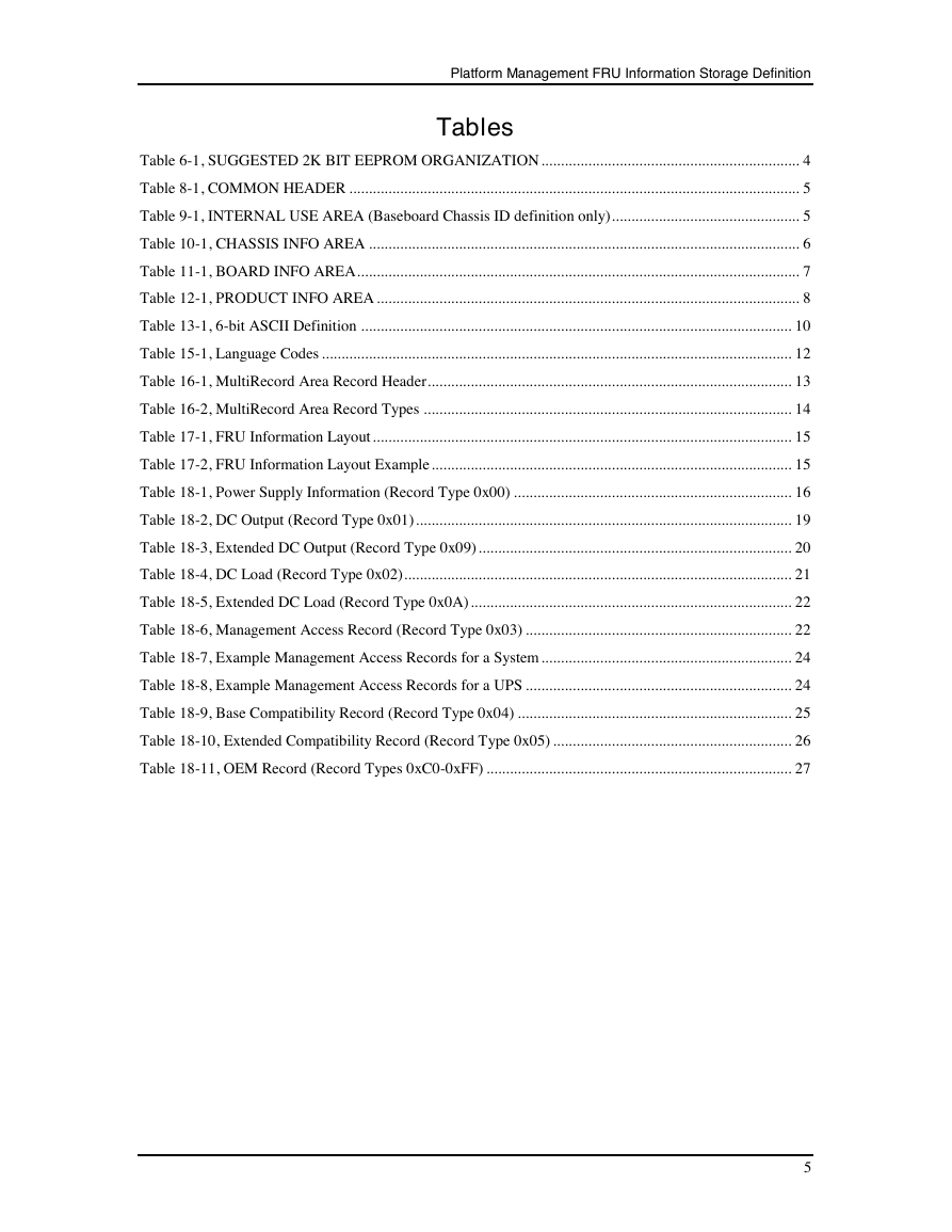
Table 6-1, SUGGESTED 2K BIT EEPROM ORGANIZATION .................................................................. 4
Table 8-1, COMMON HEADER ................................................................................................................... 5
Table 9-1, INTERNAL USE AREA (Baseboard Chassis ID definition only) ................................................ 5
Table 10-1, CHASSIS INFO AREA .............................................................................................................. 6
Table 11-1, BOARD INFO AREA ................................................................................................................. 7
Table 12-1, PRODUCT INFO AREA ............................................................................................................ 8
Table 13-1, 6-bit ASCII Definition .............................................................................................................. 10
Table 15-1, Language Codes ........................................................................................................................ 12
Table 16-1, MultiRecord Area Record Header ............................................................................................. 13
Table 16-2, MultiRecord Area Record Types .............................................................................................. 14
Table 17-1, FRU Information Layout ........................................................................................................... 15
Table 17-2, FRU Information Layout Example ............................................................................................ 15
Table 18-1, Power Supply Information (Record Type 0x00) ....................................................................... 16
Table 18-2, DC Output (Record Type 0x01) ................................................................................................ 19
Table 18-3, Extended DC Output (Record Type 0x09) ................................................................................ 20
Table 18-4, DC Load (Record Type 0x02) ................................................................................................... 21
Table 18-5, Extended DC Load (Record Type 0x0A) .................................................................................. 22
Table 18-6, Management Access Record (Record Type 0x03) .................................................................... 22
Table 18-7, Example Management Access Records for a System ................................................................ 24
Table 18-8, Example Management Access Records for a UPS .................................................................... 24
Table 18-9, Base Compatibility Record (Record Type 0x04) ...................................................................... 25
Table 18-10, Extended Compatibility Record (Record Type 0x05) ............................................................. 26
Table 18-11, OEM Record (Record Types 0xC0-0xFF) .............................................................................. 27
5
�
Platform Management FRU Information Storage Definition
6
�
1. Introduction
Platform Management FRU Information Storage Definition
This document defines and describes the common format and use of the FRU (Field Replaceable Unit)
Information storage in platforms using the Intelligent Platform Management Interface.
The FRU Information is used to primarily to provide ‘inventory’ information about the boards that the FRU
Information Device is located on. It is a goal that all major field replaceable units (FRUs) have an
EEPROM or FRU Information Device from which, at a minimum, the part number or version number can
be read through software. It is also a goal that the FRUs serial number be software readable.
The format divides the FRU Information Device (or EEPROM) into six different areas:
Common Header
Internal Use Area
Chassis Info Area
Board Info Area
The Common Header is mandatory for all FRU Information Device
implementations. It holds version information for the overall information format
specification and offsets to the other information areas. The other areas may or
may not be present based on the application of the device. An area is specified as
‘Null’ or ‘not present’ when the Common Header has a value of 00h for the
starting offset for that area.
This area provides private, implementation-specific information storage for other
devices that exist on the same FRU as the FRU Information Device. The Internal
Use Area is usually used to provide private non-volatile storage for a
management controller.
This area is used to hold Serial Number, Part Number, and other information
about the system chassis. A system can have multiple FRU Information Devices
within a chassis, but only one device should provide the Chassis Info Area. Thus,
this area will typically be absent from most FRU Information Devices. Ideally
this information is in a FRU device that is part of a board that is associated with
the chassis, such as a front panel or power distribution board. But many systems,
particularly low-end systems, do not incorporate such locations. Therefore, it is
common to find the Chassis Info Area included in the FRU information for the
baseboard.
This area provides Serial Number, Part Number, and other information about the
board that the FRU Information Device is located on. The name ‘Board Info
Area’ is somewhat a misnomer, because the usage is not restricted to just circuit
boards. This area is also typically used to provide FRU information for any
replaceable entities, boards, or sub-assemblies that are not sold as standalone
products separate from other components. For example, individual boards from a
board set, or a sub-chassis or backplane that’s part of a larger chassis.1
Product Info Area
This area is present if the FRU itself is a separate product. This is typically seen
when the FRU is an add-in card, sub-assembly, or a power supply from a
separate vendor, etc. When this area is provided in the FRU Information Device
1 The FRU device that provides info for the chassis is often implemented in the same physical device that provides FRU
info for the overall product. In such a case, it is common to have both a product info area and a chassis info area in the
device. This device may reside on the motherboard or on a chassis-related board, such as a circuit board for front panel
controls. If the overall product and the chassis share the same basic identification information, then it is also common to
have duplicate fields between the records. If the chassis is orderable as a separate replacement parts of the overall
product, however, then the serial # and part # in the chassis info would typically be different than that for the overall
product. Note that because the board info area provides a bit more info than the Chassis Info alone, it is also typical to
include a board info area along with the chassis info, though that's not mandatory.
1
�
Platform Management FRU Information Storage Definition
that contains the Chassis Info Area, the product info is for the overall system, as
initially manufactured.
MultiRecord Info Area The MultiRecord Info Area provides a region that holds one or more records
where the type and format of the information is specified in the individual
headers for the records. This differs from the other information areas, where the
type and format of the information are implied by which offset is used in the
Common Header. The MultiRecord Info Area provides a mechanism for
extending the FRU Information Specification to cover new information types
without impacting the existing area definitions.
2. Reference Documents
The following documents are companion and supporting specifications for this document:
[IPMI_1.0]
[IPMI_1.5]
[IPMI_2.0]
[ASF_2.0]
[SMBIOS]
Intelligent Platform Management Interface Specification, Version 1.0, © 1998,
1999 Intel Corporation, Hewlett-Packard Company, NEC Corporation, Dell
Computer Corporation.
Intelligent Platform Management Interface Specification, Version 1.5, © 1999,
2000, 2002, Intel Corporation, Hewlett-Packard Company, NEC Corporation,
Dell Computer Corporation
Intelligent Platform Management Interface Specification - Second Generation,
v2.0, © 2009, Intel Corporation, Hewlett-Packard Company, NEC Corporation,
Dell Computer Corporation
Alert Standard Format (ASF) Specification, Version 2.0, 23 April 2003, © 2000-
2002, Distributed Management Task Force, Inc. (DMTF)
System Management BIOS (SMBIOS) Reference Specification, Version 2.7.1,
January 26, 2011.
[UNICODE]
The Unicode Standard, Version 6.2 – Core Specification, The Unicode
Consortium, © 1991–2012 Unicode, Inc.
3. Accessing FRU Inventory Devices
Storage for FRU Inventory Devices can be provided by storage devices that are located directly on the
Intelligent Management Bus, or on a ‘Private Management Bus’. In this case, the device is typically
accessed directly using whatever low-level access interface the device provides.
Because system software needs to know the particular details of how to access the storage device, only a
limited number of types of storage devices are supported for direct access. Presently, the supported devices
are SEEPROMs that use a ‘24C02’-compatible interface, and SEEPROMs that are compatible with the
Dallas Semiconductor DS1624 Temperature Sensor/SEEPROM interface.
Alternately, a management controller can be used to provide the interface to the FRU Inventory Device. The
management controller provides Read/Write FRU Inventory Data commands for accessing the non-volatile
storage contents via the controller’s messaging interface. This is the preferred implementation. The
approach provides additional data integrity checking and error handling that are not available when a non-
volatile storage device is accessed directly. It also isolates software from the implementation of the non-
volatile storage hardware. That is, software uses the same Read/Write FRU Inventory Data commands to
the management controller regardless of the type of device used to provide the storage.
2
�



 2023年江西萍乡中考道德与法治真题及答案.doc
 2012年重庆南川中考生物真题及答案.doc
 2013年江西师范大学地理学综合及文艺理论基础考研真题.doc
 2020年四川甘孜小升初语文真题及答案I卷.doc
 2020年注册岩土工程师专业基础考试真题及答案.doc
 2023-2024学年福建省厦门市九年级上学期数学月考试题及答案.doc
 2021-2022学年辽宁省沈阳市大东区九年级上学期语文期末试题及答案.doc
 2022-2023学年北京东城区初三第一学期物理期末试卷及答案.doc
 2018上半年江西教师资格初中地理学科知识与教学能力真题及答案.doc
 2012年河北国家公务员申论考试真题及答案-省级.doc
 2020-2021学年江苏省扬州市江都区邵樊片九年级上学期数学第一次质量检测试题及答案.doc
 2022下半年黑龙江教师资格证中学综合素质真题及答案.doc