logo资料库

53346-DS06-RDS.pdf

第1页 / 共166页
第2页 / 共166页
第3页 / 共166页
第4页 / 共166页
第5页 / 共166页
第6页 / 共166页
第7页 / 共166页
第8页 / 共166页
资料共166页,剩余部分请下载后查看
Revision History
Table of Contents
List of Figures
List of Tables
About This Document
Purpose and Audience
Acronyms and Abbreviations
Document Conventions
References
Technical Support
Section 1: Introduction
Overview
Ethernet Switch Controller
ARM Cortex-A9 Processor
Section 2: Common Interfaces
System Reset
Power Sequencing
JTAG
Section 3: Ethernet Switch Controller Features Description
Architecture
Feature Overview
Memory
Address Management
Class of Service
Strict Priority-Based Scheduling
Weighted Round Robin Scheduling
Deficit Round Robin Scheduling
Simple Random Early Detection
Backpressure Handling
Per Port Packet Rate (Storm) Control
Mirroring
Spanning Tree Support
IEEE 802.1D Support
Port Filtering Mode A
Port Filtering Mode B
Port Filtering Mode C
IEEE 802.1Q Support
Link Aggregation
Double-Tagging
Forwarding Control Block Mask
ContentAware Processing
Ingress Filter Processor (IFP)
Network Management Support
CPU/Management Interface
External CPU with PCIe Bus
Energy Efficient Ethernet
Section 4: Ethernet Switch Controller System Interfaces
Overview
SerDes Warpcore
TSC Ports
10GbE (XAUI)
HIGIG+/HIGIG2 Interface
HiGig_Lite Frame Structure
HiGig-Duo[13] Interface
1G/2.5G/5G Interface
1GbE (QSGMII/SGMII)
MII Management
Broadcom Serial Interface (BSC)
LED Interfaces
Serial LED Mode
PHY-driven Parallel LED Mode
Serial to Parallel LED Mode
Ethernet Time Synchronization (Synchronous Ethernet)
IEEE 1588
Section 5: Gigabit Ethernet Transceiver
Copper Interface
Encoder
Decoder
Link Monitor
Digital Adaptive Equalizer
Echo Canceler
Crosstalk Canceler
Analog-to-Digital Converter
Clock Recovery/Generator
Baseline Wander Correction
Multimode TX Digital-to-Analog Converter
Stream Cipher
Wire Map and Pair Skew Correction
Automatic MDI Crossover
1000BASE-T Operation
10/100BASE-TX Operation (Auto-Negotiation Enabled)
10/100BASE-TX Operation (Forced Mode)
Full-Duplex Mode
Master/Slave Configuration
Next Page Exchange
Auto-Negotiation
Ethernet@Wirespeed
Ethernet@Wirespeed Example
Enabling/Disabling Ethernet@Wirespeed
Removing Ethernet@Wirespeed Downgrade
Changing the Number of Failed Link Attempts
Monitoring Ethernet@Wirespeed
Super Isolate Mode
Software Enable/Disable
Standby Power-Down Mode
Auto Power-Down (APD) Mode
ADP Mode Enable (Auto-Negotiation Enabled)
Sleep Cycle Settings
Wake Cycle Settings
Section 6: ARM Cortex-A9 Processor Subsystem Functional Description
Cortex-A9
DDR SDRAM Interface
PCI Express Gen-2 Interface
Transaction Layer Interface
Data Link Layer
Physical Layer
Electrical Subblock
Configuration Space
NOR Serial Flash Interface
NOR Parallel Flash Interface
NAND Flash Interface
MIIM/UART/GPIO Interfaces
SPI interface
MII Interface
Section 7: Pin List Description
Signal Name Descriptions
Pin List by Pin Name
Pin List by Signal Name
Section 8: Electrical Specifications
Absolute Maximum Ratings
DC Characteristics
Operating Conditions
Power-Up and Power-Down Specifications
Power Supply Current
Standard 3.3V Signals
PCIe DC Characteristics
BSC Signals
SGMII/SerDes Signals
2.5GbE SerDes Signals
QSGMII SerDes Signals
Warpcore Technology Quad SerDes Signals
MIIM (MDIO) Signals
AC Characteristics
MII Interface Timing
MII Input Timing
MII Output Timing
AC Timing for Reset
BSC AC Characteristics
SPI AC Characteristics
MDIO AC Characteristics
JTAG AC Specifications
NAND Flash Interface Timing
NOR Flash Interface Timing
Synchronous Ethernet Interface Timing
L1_RCVRD_CLK and L1_RCVRD_CLK_BKUP Output Timing
L1_RCVRD_CLK_VALID and L1_RCVRD_CLK Output Timing
QSPI Flash Interface Timing
DDR3 Interface AC Specifications
DDR3 Address and Control Timing
DDR3 Write Timing
DDR3 Read Timing
PCIe Interface Timing
PCIE_REFCLK Timing
PCIe_RX Timing
PCIe_TX Timing
LED Controller Interface
XTAL Clock Requirements
XG_PLL2_REFCLK Clock Requirements
LC_PLL1_REFCLK Clock Requirements
LC_PLL0_REFCLK Clock Requirements
EXT_QS2_CLKP/N Clock Specifications
QSGMII AC Specifications
Transmitter
Receiver
SGMII AC Specifications
SGMII/SerDes Interface Output Timing
SGMII/SerDes Interface Input Timing
2.5GbE SerDes AC Specifications
2.5GbE/SerDes Interface Output Timing
2.5GbE/SerDes Interface Input Timing
Warpcore Technology Serial Interface AC Specification
WCx_TDy Transmit Preemphasis Setting
10GBASE-KR Electrical Characteristics
Transmitter
Receiver
AC-JTAG
Section 9: Thermal Characteristics
Section 10: Mechanical Information
Section 11: Ordering Information
Appendix A: Acronyms and Abbreviations
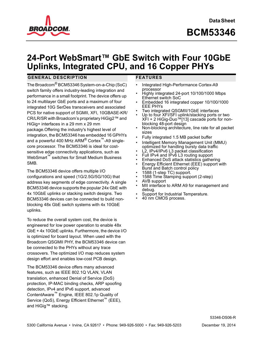
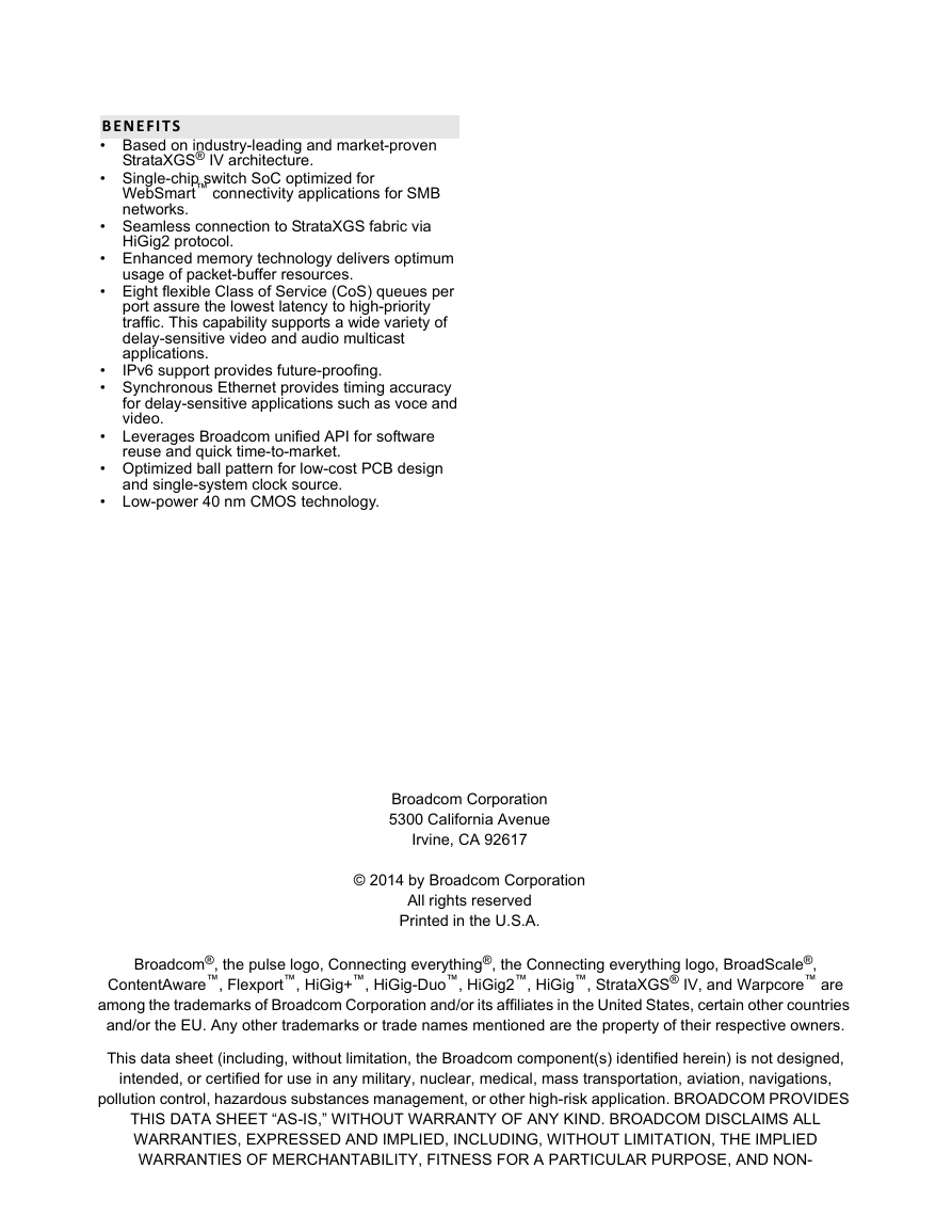
Data Sheet BCM53346 24-Port WebSmart™ GbE Switch with Four 10GbE Uplinks, Integrated CPU, and 16 Copper PHYs Integrated High-Performance Cortex-A9 processor Ethernet switch SoC EEE PHYs FEATURES • • Highly integrated 24-port 10/100/1000 Mbps • Embedded 16 integrated copper 10/100/1000 • Two integrated QSGMII/1GbE interfaces • Up to four XFI/SFI uplink/stacking ports or two XFI + 2 HiGig-Duo™[13] cascade ports for non- blocking 48-port design • Non-blocking architecture, line rate for all packet sizes Intelligent Memory Management Unit (MMU) optimized for handling bursty data traffic • Fully integrated 1.5 MB packet buffer • • L2, IPv4/IPv6 L3 packet classification • Full IPv4 and IPv6 L3 routing support • Enhanced DoS attack statistics gathering • Energy Efficient Ethernet (EEE) support with • 1588 (1-step TC) support. • 1588 Time Stamping support (2-step) • AVB support • MII interface to ARM A9 for management and • Support for Industrial Temperature. • 40 nm CMOS process. Burst and Batch control policy debug. GENERAL DESCRIPTION The Broadcom® BCM53346 System-on-a-Chip (SoC) switch family offers industry-leading integration and performance in a small footprint. The device offers up to 24 multilayer GbE ports and a maximum of four integrated 10G SerDes transceivers and associated PCS for native support of SGMII, XFI, 10GBASE-KR/ CR/LR/SR with Broadcom’s proprietary HiGig2™ and HiGig+ interfaces in a 29 mm x 29 mm package.Offering the industry's highest level of integration, the BCM53346 has embedded 16 GPHYs and a powerful 400 MHz ARM® Cortex™-A9 single- core processor. The BCM53346 is ideal for cost- sensitive edge connectivity applications, such as WebSmart™ switches for Small Medium Business SMB. The BCM53346 device offers multiple I/O configurations and speed (1G/2.5G/5G/10G) that address key segments of edge connectivity. A single BCM53346 device supports the popular 24x GbE with 4x 10GbE uplinks or stacking switch designs. Two BCM53346 devices can be connected to build non- blocking 48x GbE switch systems with 4x 10GbE uplinks. To reduce the overall system cost, the device is engineered for low power operation to enable 48x GbE + 4x 10GbE uplinks. Furthermore, the device I/O is optimized for board layout. When used with the Broadcom QSGMII PHY, the BCM53346 device can be connected to the PHYs without any trace crossovers. The optimized I/O map reduces system design effort and enables low-cost PCB design. The BCM53346 device offers many advanced features, such as IEEE 802.1Q VLAN, VLAN translation, enhanced Denial of Service (DoS) protection, IP-MAC binding checks, ARP spoofing detection, IPv4 and IPv6 support, advanced ContentAware™ Engine, IEEE 802.1p Quality of Service (QoS), Energy Efficient Ethernet™ (EEE), and HiGig™ stacking. 5300 California Avenue • Irvine, CA 92617 • Phone: 949-926-5000 • Fax: 949-926-5203 53346-DS06-R December 19, 2014
BENEFITS • Based on industry-leading and market-proven • Single-chip switch SoC optimized for StrataXGS® IV architecture. WebSmart™ connectivity applications for SMB networks. • Seamless connection to StrataXGS fabric via HiGig2 protocol. • Optimized ball pattern for low-cost PCB design and single-system clock source. • Low-power 40 nm CMOS technology. • Enhanced memory technology delivers optimum usage of packet-buffer resources. • Eight flexible Class of Service (CoS) queues per port assure the lowest latency to high-priority traffic. This capability supports a wide variety of delay-sensitive video and audio multicast applications. IPv6 support provides future-proofing. • • Synchronous Ethernet provides timing accuracy for delay-sensitive applications such as voce and video. • Leverages Broadcom unified API for software reuse and quick time-to-market. Broadcom Corporation 5300 California Avenue Irvine, CA 92617 © 2014 by Broadcom Corporation All rights reserved Printed in the U.S.A. Broadcom®, the pulse logo, Connecting everything®, the Connecting everything logo, BroadScale®, ContentAware™, Flexport™, HiGig+™, HiGig-Duo™, HiGig2™, HiGig™, StrataXGS® IV, and Warpcore™ are among the trademarks of Broadcom Corporation and/or its affiliates in the United States, certain other countries and/or the EU. Any other trademarks or trade names mentioned are the property of their respective owners. This data sheet (including, without limitation, the Broadcom component(s) identified herein) is not designed, intended, or certified for use in any military, nuclear, medical, mass transportation, aviation, navigations, pollution control, hazardous substances management, or other high-risk application. BROADCOM PROVIDES THIS DATA SHEET “AS-IS,” WITHOUT WARRANTY OF ANY KIND. BROADCOM DISCLAIMS ALL WARRANTIES, EXPRESSED AND IMPLIED, INCLUDING, WITHOUT LIMITATION, THE IMPLIED WARRANTIES OF MERCHANTABILITY, FITNESS FOR A PARTICULAR PURPOSE, AND NON-
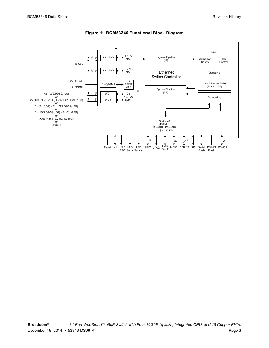
BCM53346 Data Sheet Revision History Figure 1: BCM53346 Functional Block Diagram 16 GbE . . . 2x QSGMII or 2x SGMII 4x (1G/2.5G/5G/10G) or or or or 2x (1G/2.5G/5G/10G) + 2x (1G/2.5G/5G/10G) 2x (2 x 6.5G) + 2x (1G/2.5G/5G/10G) 2x (1G/2.5G/5G/10G) + 2x (2 x 6.5G) XAUI + 3x (1G/2.5G/5G/10G) or 2x XAUI 8 x GPHY 8 x GPHY 2 x QSGMII WC 1 WC 0 8 x 1G MAC 8 x 1G MAC 8 x FE/1G MAC 2 x 4 x 10G XMAC Ingress Pipeline (IP) Ethernet Switch Controller Egress Pipeline (EP) MMU Admission Control Flow Control Queueing 1.5 MB Packet Buffer (12K x 128B) Scheduling Cortex-A9 400 MHz I$ = 32K / D$ = 32K L2$ = 128 KB Reset MII I2C/ BSC LED Serial LED Parallel GPIO JTAG PCIe Gen 2 MDIO DDR2/3 SPI Serial Flash Parallel Flash RS-232 16 x3 16 x2 Broadcom® December 19, 2014 • 53346-DS06-R 24-Port WebSmart™ GbE Switch with Four 10GbE Uplinks, Integrated CPU, and 16 Copper PHYs Page 3
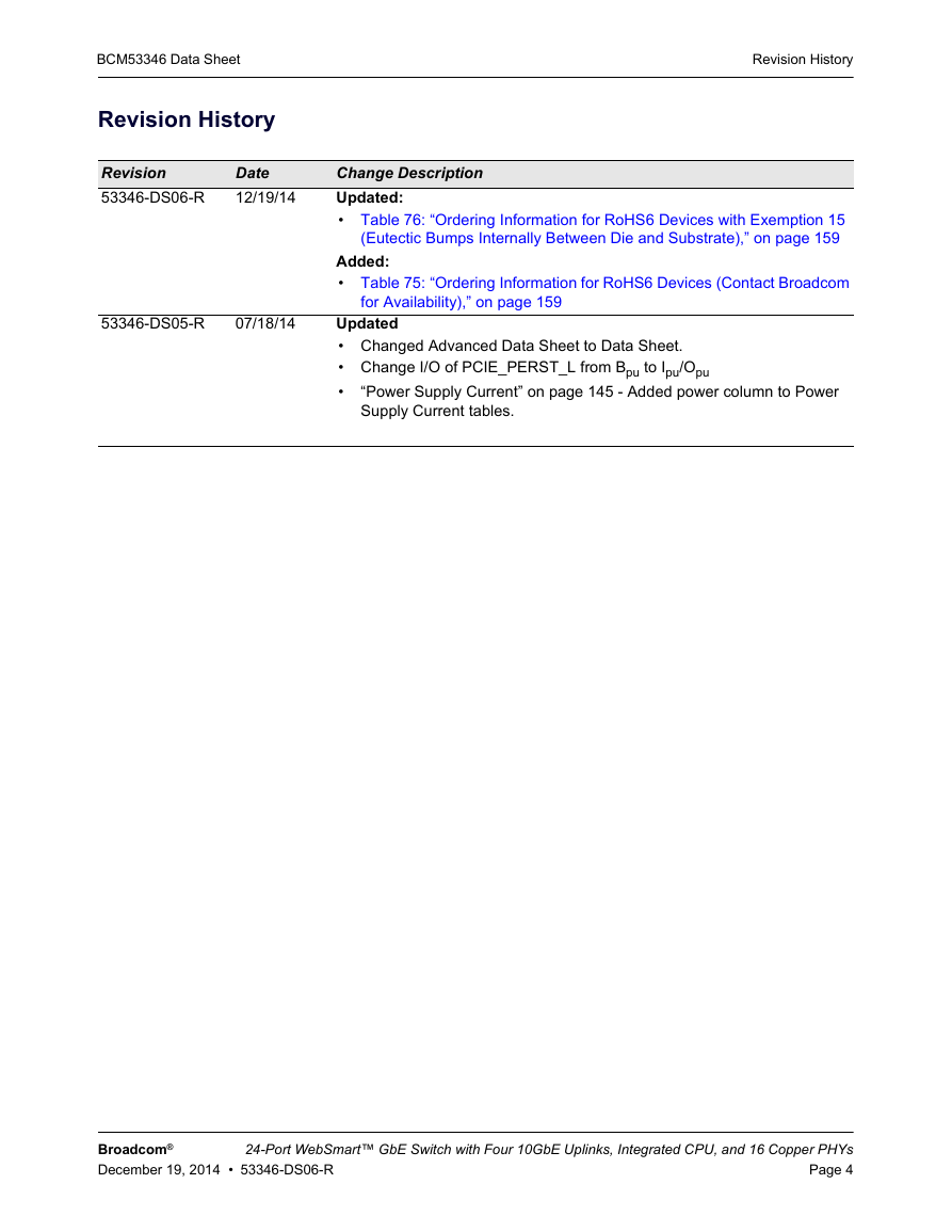
BCM53346 Data Sheet Revision History Revision 53346-DS06-R Date 12/19/14 53346-DS05-R 07/18/14 Revision History Change Description Updated: • Table 76: “Ordering Information for RoHS6 Devices with Exemption 15 (Eutectic Bumps Internally Between Die and Substrate),” on page 159 Added: • Table 75: “Ordering Information for RoHS6 Devices (Contact Broadcom for Availability),” on page 159 Updated • Changed Advanced Data Sheet to Data Sheet. • Change I/O of PCIE_PERST_L from Bpu to Ipu/Opu • “Power Supply Current” on page 145 - Added power column to Power Supply Current tables. Broadcom® December 19, 2014 • 53346-DS06-R 24-Port WebSmart™ GbE Switch with Four 10GbE Uplinks, Integrated CPU, and 16 Copper PHYs Page 4
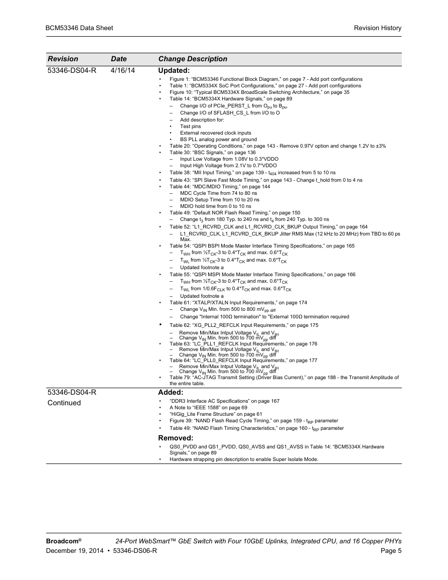
BCM53346 Data Sheet Revision 53346-DS04-R Date 4/16/14 53346-DS04-R Continued Revision History Change Description Updated: • • • • Figure 1: “BCM53346 Functional Block Diagram,” on page 7 - Add port configurations Table 1: “BCM5334X SoC Port Configurations,” on page 27 - Add port configurations Figure 10: “Typical BCM5334X BroadScale Switching Architecture,” on page 35 Table 14: “BCM5334X Hardware Signals,” on page 89 Change I/O of PCIe_PERST_L from Opu to Bpu. – Change I/O of SFLASH_CS_L from I/O to O – Add description for: – Test pins • • External recovered clock inputs • BS PLL analog power and ground Table 20: “Operating Conditions,” on page 143 - Remove 0.97V option and change 1.2V to ±3% Table 30: “BSC Signals,” on page 136 – – Table 38: “MII Input Timing,” on page 139 - t404 increased from 5 to 10 ns Table 43: “SPI Slave Fast Mode Timing,” on page 143 - Change t_hold from 0 to 4 ns Table 44: “MDC/MDIO Timing,” on page 144 – MDC Cycle Time from 74 to 80 ns – MDIO Setup Time from 10 to 20 ns – MDIO hold time from 0 to 10 ns Table 49: “Default NOR Flash Read Timing,” on page 150 – Table 52: “L1_RCVRD_CLK and L1_RCVRD_CLK_BKUP Output Timing,” on page 164 – Input Low Voltage from 1.08V to 0.3*VDDO Input High Voltage from 2.1V to 0.7*VDDO Change t3 from 180 Typ. to 240 ns and t4 from 240 Typ. to 300 ns L1_RCVRD_CLK, L1_RCVRD_CLK_BKUP Jitter RMS Max (12 kHz to 20 MHz) from TBD to 60 ps Max. TWH from ½TCK-3 to 0.4*TCK and max. 0.6*TCK TWL from ½TCK-3 to 0.4*TCK and max. 0.6*TCK Updated footnote a TWH from ½TCK-3 to 0.4*TCK and max. 0.6*TCK TWL from 1/0.6FCLK to 0.4*TCK and max. 0.6*TCK Updated footnote a Change VIN Min. from 500 to 800 mVpp diff Change "Internal 100Ω termination" to "External 100Ω termination required Table 54: “QSPI BSPI Mode Master Interface Timing Specifications,” on page 165 – – – Table 55: “QSPI MSPI Mode Master Interface Timing Specifications,” on page 166 – – – Table 61: “XTALP/XTALN Input Requirements,” on page 174 – – Table 62: “XG_PLL2_REFCLK Input Requirements,” on page 175 – Remove Min/Max Intput Voltage VIL and VIH – Change VIN Min. from 500 to 700 mVpp diff Table 63: “LC_PLL1_REFCLK Input Requirements,” on page 176 – Remove Min/Max Intput Voltage VIL and VIH – Change VIN Min. from 500 to 700 mVpp diff Table 64: “LC_PLL0_REFCLK Input Requirements,” on page 177 – Remove Min/Max Intput Voltage VIL and VIH – Change VIN Min. from 500 to 700 mVpp diff Table 79: “AC-JTAG Transmit Setting (Driver Bias Current),” on page 188 - the Transmit Amplitude of the entire table. • • • • • • • • • • • • • • “DDR3 Interface AC Specifications” on page 167 A Note to “IEEE 1588” on page 69 “HiGig_Lite Frame Structure” on page 61 Figure 39: “NAND Flash Read Cycle Timing,” on page 159 - tRP parameter Table 49: “NAND Flash Timing Characteristics,” on page 160 - tRP parameter Added: • • • • • Removed: • QS0_PVDD and QS1_PVDD, QS0_AVSS and QS1_AVSS in Table 14: “BCM5334X Hardware Signals,” on page 89 Hardware strapping pin description to enable Super Isolate Mode. • Broadcom® December 19, 2014 • 53346-DS06-R 24-Port WebSmart™ GbE Switch with Four 10GbE Uplinks, Integrated CPU, and 16 Copper PHYs Page 5
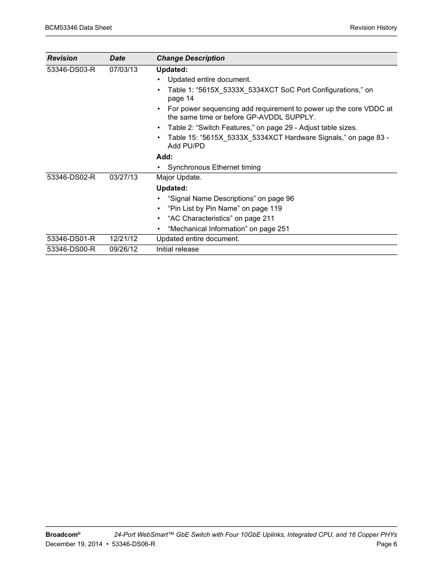
BCM53346 Data Sheet Revision History Revision 53346-DS03-R Date 07/03/13 Change Description Updated: • Updated entire document. • Table 1: “5615X_5333X_5334XCT SoC Port Configurations,” on page 14 • For power sequencing add requirement to power up the core VDDC at the same time or before GP-AVDDL SUPPLY. • Table 2: “Switch Features,” on page 29 - Adjust table sizes. • Table 15: “5615X_5333X_5334XCT Hardware Signals,” on page 83 - Add PU/PD 53346-DS02-R 03/27/13 53346-DS01-R 53346-DS00-R 12/21/12 09/26/12 Add: • Synchronous Ethernet timing Major Update. Updated: • • • • Updated entire document. Initial release “Signal Name Descriptions” on page 96 “Pin List by Pin Name” on page 119 “AC Characteristics” on page 211 “Mechanical Information” on page 251 Broadcom® December 19, 2014 • 53346-DS06-R 24-Port WebSmart™ GbE Switch with Four 10GbE Uplinks, Integrated CPU, and 16 Copper PHYs Page 6
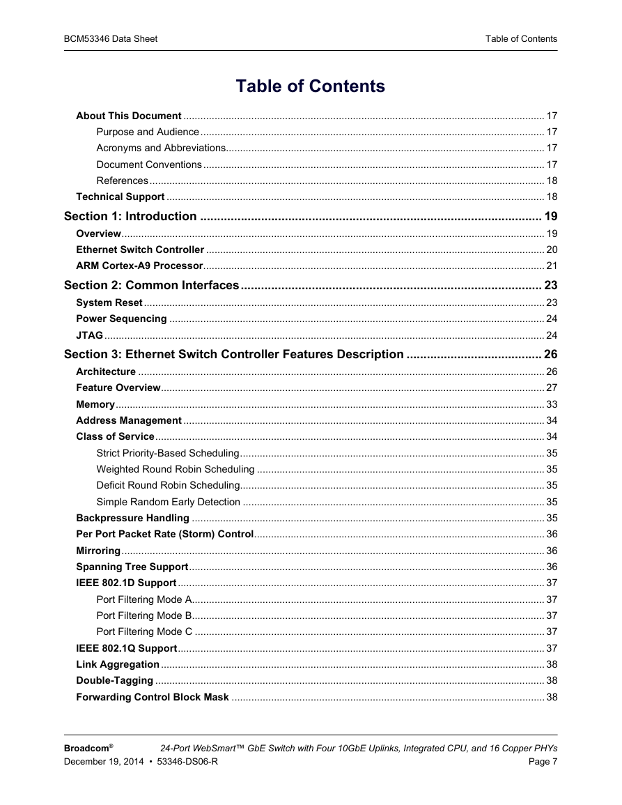
BCM53346 Data Sheet Table of Contents Table of Contents About This Document ................................................................................................................................ 17 Purpose and Audience.......................................................................................................................... 17 Acronyms and Abbreviations................................................................................................................. 17 Document Conventions......................................................................................................................... 17 References............................................................................................................................................ 18 Technical Support ...................................................................................................................................... 18 Section 1: Introduction ..................................................................................................... 19 Overview...................................................................................................................................................... 19 Ethernet Switch Controller ........................................................................................................................ 20 ARM Cortex-A9 Processor......................................................................................................................... 21 Section 2: Common Interfaces......................................................................................... 23 System Reset.............................................................................................................................................. 23 Power Sequencing ..................................................................................................................................... 24 JTAG............................................................................................................................................................ 24 Section 3: Ethernet Switch Controller Features Description ........................................ 26 Architecture ................................................................................................................................................ 26 Feature Overview........................................................................................................................................ 27 Memory........................................................................................................................................................ 33 Address Management ................................................................................................................................ 34 Class of Service.......................................................................................................................................... 34 Strict Priority-Based Scheduling............................................................................................................ 35 Weighted Round Robin Scheduling ...................................................................................................... 35 Deficit Round Robin Scheduling............................................................................................................ 35 Simple Random Early Detection ........................................................................................................... 35 Backpressure Handling ............................................................................................................................. 35 Per Port Packet Rate (Storm) Control....................................................................................................... 36 Mirroring...................................................................................................................................................... 36 Spanning Tree Support.............................................................................................................................. 36 IEEE 802.1D Support.................................................................................................................................. 37 Port Filtering Mode A............................................................................................................................. 37 Port Filtering Mode B............................................................................................................................. 37 Port Filtering Mode C ............................................................................................................................ 37 IEEE 802.1Q Support.................................................................................................................................. 37 Link Aggregation........................................................................................................................................ 38 Double-Tagging .......................................................................................................................................... 38 Forwarding Control Block Mask ............................................................................................................... 38 Broadcom® December 19, 2014 • 53346-DS06-R 24-Port WebSmart™ GbE Switch with Four 10GbE Uplinks, Integrated CPU, and 16 Copper PHYs Page 7
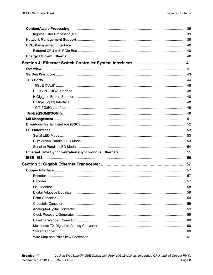
BCM53346 Data Sheet Table of Contents ContentAware Processing......................................................................................................................... 39 Ingress Filter Processor (IFP) ............................................................................................................... 39 Network Management Support.................................................................................................................. 39 CPU/Management Interface....................................................................................................................... 40 External CPU with PCIe Bus................................................................................................................. 40 Energy Efficient Ethernet........................................................................................................................... 40 Section 4: Ethernet Switch Controller System Interfaces ............................................. 41 Overview...................................................................................................................................................... 41 SerDes Warpcore........................................................................................................................................ 43 TSC Ports .................................................................................................................................................... 44 10GbE (XAUI) ....................................................................................................................................... 46 HIGIG+/HIGIG2 Interface...................................................................................................................... 48 HiGig_Lite Frame Structure................................................................................................................... 48 HiGig-Duo[13] Interface......................................................................................................................... 48 1G/2.5G/5G Interface............................................................................................................................ 49 1GbE (QSGMII/SGMII)................................................................................................................................. 49 MII Management.......................................................................................................................................... 51 Broadcom Serial Interface (BSC).............................................................................................................. 52 LED Interfaces ............................................................................................................................................ 53 Serial LED Mode ................................................................................................................................... 53 PHY-driven Parallel LED Mode............................................................................................................. 53 Serial to Parallel LED Mode .................................................................................................................. 54 Ethernet Time Synchronization (Synchronous Ethernet)....................................................................... 55 IEEE 1588 .................................................................................................................................................... 56 Section 5: Gigabit Ethernet Transceiver ......................................................................... 57 Copper Interface......................................................................................................................................... 57 Encoder................................................................................................................................................. 57 Decoder................................................................................................................................................. 57 Link Monitor........................................................................................................................................... 58 Digital Adaptive Equalizer ..................................................................................................................... 59 Echo Canceler....................................................................................................................................... 59 Crosstalk Canceler................................................................................................................................ 59 Analog-to-Digital Converter................................................................................................................... 59 Clock Recovery/Generator.................................................................................................................... 59 Baseline Wander Correction ................................................................................................................. 60 Multimode TX Digital-to-Analog Converter............................................................................................ 60 Stream Cipher ....................................................................................................................................... 60 Wire Map and Pair Skew Correction ..................................................................................................... 61 Broadcom® December 19, 2014 • 53346-DS06-R 24-Port WebSmart™ GbE Switch with Four 10GbE Uplinks, Integrated CPU, and 16 Copper PHYs Page 8
分享到:
收藏