X10DRL-i
USER’S MANUAL
Revision 1.1b
�
The information in this User’s Manual has been carefully reviewed and is believed to be accurate.
The vendor assumes no responsibility for any inaccuracies that may be contained in this document,
and makes no commitment to update or to keep current the information in this manual, or to notify
any person or organization of the updates. Please Note: For the most up-to-date version of this
manual, please see our website at www.supermicro.com.
Super Micro Computer, Inc. ("Supermicro") reserves the right to make changes to the product
described in this manual at any time and without notice. This product, including software and docu-
mentation, is the property of Supermicro and/or its licensors, and is supplied only under a license.
Any use or reproduction of this product is not allowed, except as expressly permitted by the terms
of said license.
IN NO EVENT WILL SUPER MICRO COMPUTER, INC. BE LIABLE FOR DIRECT, INDIRECT,
SPECIAL, INCIDENTAL, SPECULATIVE OR CONSEQUENTIAL DAMAGES ARISING FROM THE
USE OR INABILITY TO USE THIS PRODUCT OR DOCUMENTATION, EVEN IF ADVISED OF
THE POSSIBILITY OF SUCH DAMAGES. IN PARTICULAR, SUPER MICRO COMPUTER, INC.
SHALL NOT HAVE LIABILITY FOR ANY HARDWARE, SOFTWARE, OR DATA STORED OR USED
WITH THE PRODUCT, INCLUDING THE COSTS OF REPAIRING, REPLACING, INTEGRATING,
INSTALLING OR RECOVERING SUCH HARDWARE, SOFTWARE, OR DATA.
Any disputes arising between the manufacturer and the customer shall be governed by the laws of
Santa Clara County in the State of California, USA. The State of California, County of Santa Clara
shall be the exclusive venue for the resolution of any such disputes. Supermicro's total liability for
all claims will not exceed the price paid for the hardware product.
FCC Statement: This equipment has been tested and found to comply with the limits for a Class A
digital device pursuant to Part 15 of the FCC Rules. These limits are designed to provide reasonable
protection against harmful interference when the equipment is operated in industrial environment.
This equipment generates, uses, and can radiate radio frequency energy and, if not installed and
used in accordance with the manufacturer’s instruction manual, may cause harmful interference with
radio communications. Operation of this equipment in a residential area is likely to cause harmful
interference, in which case you will be required to correct the interference at your own expense.
California Best Management Practices Regulations for Perchlorate Materials: This Perchlorate
warning applies only to products containing CR (Manganese Dioxide) Lithium coin cells. “Perchlorate
Material-special handling may apply. See www.dtsc.ca.gov/hazardouswaste/perchlorate”.
!
WARNING: This product can expose you to chemicals including
lead, known to the State of California to cause cancer and birth
defects or other reproductive harm. For more information, go
to www.P65Warnings.ca.gov.
Manual Revision 1.1b
Release Date: February 24, 2020
Unless you request and receive written permission from Super Micro Computer, Inc., you may not
copy any part of this document.
Information in this document is subject to change without notice. Other products and companies
referred to herein are trademarks or registered trademarks of their respective companies or mark
holders.
Copyright © 2020 by Super Micro Computer, Inc.
All rights reserved.
Printed in the United States of America
�
Preface
Preface
This manual is written for system integrators, IT Professionals, and
knowledgeable PC users. It provides information for the installation and use of the
X10DRL-i motherboard.
About This Motherboard
The Super X10DRL-i motherboard supports dual Intel E5-2600v3/v4 Series Proces-
sors (Socket R3) that offer new Intel Microarchitecture 22nm (E5-2600v3)/14nm
(E5-2600v4) Process Technology, delivering the best balanced solution of perfor-
mance, power efficiency, and features to address the diverse needs of next-gener-
ation data centers. With the PCH C612 built in, the X10DRL-i motherboard supports
Intel® Management Engine, MCTP Protocol, and Node Manager 3.0. This mother-
board is ideal for cost-optimized and general-purpose server platforms. Please refer
to our website (http://www.supermicro.com) for CPU and memory support updates.
Manual Organization
Chapter 1 describes the features, specifications and performance of the moth-
erboard. It also provides detailed information about the Intel PCH C612 chipset.
Chapter 2 provides hardware installation instructions. Read this chapter when in-
stalling the processor, memory modules and other hardware components into the
system. If you encounter any problems, see Chapter 3, which describes trouble-
shooting procedures for video, memory, and system setup stored in CMOS.
Chapter 4 includes an introduction to BIOS, and provides detailed information on
running the BIOS Setup utility.
Appendix A provides BIOS Error Beep Codes.
Appendix B lists Software Installation Instructions.
Appendix C contains UEFI BIOS Recovery instructions.
Appendix D provides Dual Boot Block Information.
iii
�
X10DRL-i Motherboard User’s Manual
Conventions Used in the Manual
Pay special attention to the following symbols for proper system installation:
Warning: Important information given to ensure proper system installation or to prevent
damage to the components or injury to yourself;
Note: Additional information given to ensure proper system configuration
and setup.
iv
�
Contacting Supermicro
Preface
Headquarters
Address:
Tel:
Fax:
Email:
Website:
Europe
Address:
Tel:
Fax:
Email:
Website:
Asia-Pacific
Address:
Tel:
Fax:
Email:
Website:
Super Micro Computer, Inc.
980 Rock Ave.
San Jose, CA 95131 U.S.A.
+1 (408) 503-8000
+1 (408) 503-8008
marketing@supermicro.com (General Information)
support@supermicro.com (Technical Support)
www.supermicro.com
Super Micro Computer B.V.
Het Sterrenbeeld 28, 5215 ML
's-Hertogenbosch, The Netherlands
+31 (0) 73-6400390
+31 (0) 73-6416525
sales@supermicro.nl (General Information)
support@supermicro.nl (Technical Support)
rma@supermicro.nl (Customer Support)
www.supermicro.nl
Super Micro Computer, Inc.
3F, No. 150, Jian 1st Rd.
Zhonghe Dist., New Taipei City 235
Taiwan (R.O.C)
+886-(2) 8226-3990
+886-(2) 8226-3992
support@supermicro.com.tw
www.supermicro.com.tw
v
�
X10DRL-i Motherboard User’s Manual
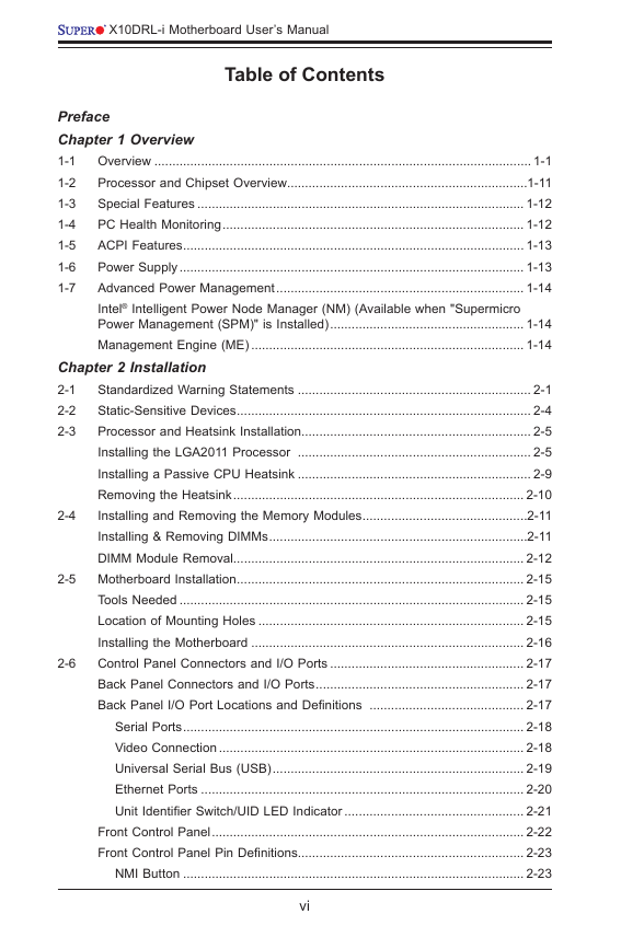
Table of Contents
Preface
Chapter 1 Overview
1-1 Overview ......................................................................................................... 1-1
1-2 Processor and Chipset Overview...................................................................1-11
1-3 Special Features ........................................................................................... 1-12
1-4 PC Health Monitoring .................................................................................... 1-12
1-5 ACPI Features ............................................................................................... 1-13
1-6 Power Supply ................................................................................................ 1-13
1-7 Advanced Power Management ..................................................................... 1-14
Intel® Intelligent Power Node Manager (NM) (Available when "Supermicro
Power Management (SPM)" is Installed) ...................................................... 1-14
Management Engine (ME) ............................................................................ 1-14
2-4
Chapter 2 Installation
2-1
Standardized Warning Statements ................................................................. 2-1
2-2 Static-Sensitive Devices .................................................................................. 2-4
2-3 Processor and Heatsink Installation................................................................ 2-5
Installing the LGA2011 Processor ................................................................. 2-5
Installing a Passive CPU Heatsink ................................................................. 2-9
Removing the Heatsink ................................................................................. 2-10
Installing and Removing the Memory Modules ..............................................2-11
Installing & Removing DIMMs ........................................................................2-11
DIMM Module Removal................................................................................. 2-12
2-5 Motherboard Installation ................................................................................ 2-15
Tools Needed ................................................................................................ 2-15
Location of Mounting Holes .......................................................................... 2-15
Installing the Motherboard ............................................................................ 2-16
2-6 Control Panel Connectors and I/O Ports ...................................................... 2-17
Back Panel Connectors and I/O Ports .......................................................... 2-17
Back Panel I/O Port Locations and Definitions ........................................... 2-17
Serial Ports ............................................................................................... 2-18
Video Connection ..................................................................................... 2-18
Universal Serial Bus (USB) ...................................................................... 2-19
Ethernet Ports .......................................................................................... 2-20
Unit Identifier Switch/UID LED Indicator .................................................. 2-21
Front Control Panel ....................................................................................... 2-22
Front Control Panel Pin Definitions............................................................... 2-23
NMI Button ............................................................................................... 2-23
vi
�
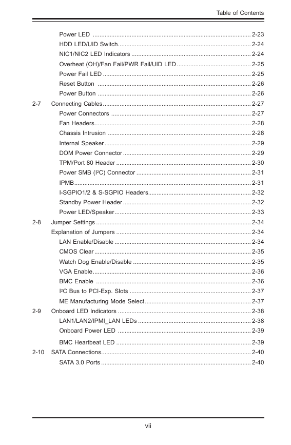
Table of Contents
Power LED .............................................................................................. 2-23
HDD LED/UID Switch ............................................................................... 2-24
NIC1/NIC2 LED Indicators ....................................................................... 2-24
Overheat (OH)/Fan Fail/PWR Fail/UID LED ............................................ 2-25
Power Fail LED ........................................................................................ 2-25
Reset Button ........................................................................................... 2-26
Power Button ........................................................................................... 2-26
2-7 Connecting Cables ........................................................................................ 2-27
Power Connectors ................................................................................... 2-27
Fan Headers ............................................................................................. 2-28
Chassis Intrusion ..................................................................................... 2-28
Internal Speaker ....................................................................................... 2-29
DOM Power Connector ............................................................................ 2-29
TPM/Port 80 Header ................................................................................ 2-30
Power SMB (I2C) Connector .................................................................... 2-31
IPMB ......................................................................................................... 2-31
I-SGPIO1/2 & S-SGPIO Headers ............................................................. 2-32
Standby Power Header ............................................................................ 2-32
Power LED/Speaker ................................................................................. 2-33
Jumper Settings ............................................................................................ 2-34
Explanation of Jumpers ................................................................................ 2-34
LAN Enable/Disable ................................................................................. 2-34
CMOS Clear ............................................................................................. 2-35
Watch Dog Enable/Disable ...................................................................... 2-35
VGA Enable .............................................................................................. 2-36
BMC Enable ............................................................................................ 2-36
I2C Bus to PCI-Exp. Slots ........................................................................ 2-37
ME Manufacturing Mode Select ............................................................... 2-37
2-9 Onboard LED Indicators ............................................................................... 2-38
LAN1/LAN2/IPMI_LAN LEDs ................................................................... 2-38
Onboard Power LED ............................................................................... 2-39
BMC Heartbeat LED ................................................................................ 2-39
2-10 SATA Connections ......................................................................................... 2-40
SATA 3.0 Ports ......................................................................................... 2-40
2-8
vii
�
X10DRL-i Motherboard User’s Manual
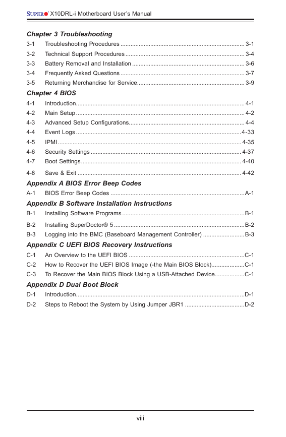
Chapter 3 Troubleshooting
3-1 Troubleshooting Procedures ........................................................................... 3-1
3-2 Technical Support Procedures ........................................................................ 3-4
3-3
Battery Removal and Installation .................................................................... 3-6
3-4 Frequently Asked Questions ........................................................................... 3-7
3-5 Returning Merchandise for Service................................................................. 3-9
Chapter 4 BIOS
4-1
Introduction ...................................................................................................... 4-1
4-2 Main Setup ...................................................................................................... 4-2
4-3 Advanced Setup Configurations...................................................................... 4-4
4-4 Event Logs ....................................................................................................4-33
IPMI ............................................................................................................... 4-35
4-5
Security Settings ........................................................................................... 4-37
4-6
4-7
Boot Settings ................................................................................................. 4-40
4-8 Save & Exit ................................................................................................... 4-42
Appendix A BIOS Error Beep Codes
A-1 BIOS Error Beep Codes .................................................................................A-1
Appendix B Software Installation Instructions
Installing Software Programs ..........................................................................B-1
B-1
B-2
Installing SuperDoctor® 5 ...............................................................................B-2
B-3 Logging into the BMC (Baseboard Management Controller) .........................B-3
Appendix C UEFI BIOS Recovery Instructions
C-1 An Overview to the UEFI BIOS ......................................................................C-1
C-2 How to Recover the UEFI BIOS Image (-the Main BIOS Block)....................C-1
C-3 To Recover the Main BIOS Block Using a USB-Attached Device..................C-1
Appendix D Dual Boot Block
D-1
Introduction ......................................................................................................D-1
D-2 Steps to Reboot the System by Using Jumper JBR1 ....................................D-2
viii
�


 2023年江西萍乡中考道德与法治真题及答案.doc
 2012年重庆南川中考生物真题及答案.doc
 2013年江西师范大学地理学综合及文艺理论基础考研真题.doc
 2020年四川甘孜小升初语文真题及答案I卷.doc
 2020年注册岩土工程师专业基础考试真题及答案.doc
 2023-2024学年福建省厦门市九年级上学期数学月考试题及答案.doc
 2021-2022学年辽宁省沈阳市大东区九年级上学期语文期末试题及答案.doc
 2022-2023学年北京东城区初三第一学期物理期末试卷及答案.doc
 2018上半年江西教师资格初中地理学科知识与教学能力真题及答案.doc
 2012年河北国家公务员申论考试真题及答案-省级.doc
 2020-2021学年江苏省扬州市江都区邵樊片九年级上学期数学第一次质量检测试题及答案.doc
 2022下半年黑龙江教师资格证中学综合素质真题及答案.doc