Lite End Multiport Repeater Interface Controller
TC3097-8
Preliminary Data Sheet
General Description
The TC3097 Lite End Multiport Repeater Interface
Controller (LEMRIC) may be used to implement
an IEEE 802.3 multiport repeater unit. It fully
satisfies the IEEE 802.3 repeater specification
including the functions defined by the repeater,
segment partition and jabber lockup protection
state machines.
The LEMRIC has an on-chip phase-locked-loop
(PLL)
for Manchester data decoding, a
Manchester encoder, and an Elasticity Buffer for
preamble regeneration. In addition, it provides
direct LED display driver pins
for per port
LINK/RCV status, per port partition jabber status,
global jam and jabber lockup status indications.
Each LEMRIC can connect up
to 9 cable
segments via its network interface ports. One port
is fully Attachment Unit Interface (AUI) compatible
and is able to connect to an external Medium
Attachment Unit (MAU) using the maximum length
of AUI cable. The other 8 ports have integrated
10BASE-T transceivers. In addition, large repeater
units may be constructed by cascading LEMRICs
together over the Inter-LEMRIC bus.
Functionally conforms to Section 9 in the IEEE
802.3 specification.
9 network connection (ports) per chip including:
1 AUI PORT with fully compatible and drive
–
capability (50m AUI cable).
8 TP PORT with fully compatible and drive
capability (100m TP cable).
Cascadable for large multiple LEMRIC hub
applications.
On-chip Elasticity buffer, Manchester encoder
and decoder.
Separate partition state machine for each port.
Embeded LED output driver for each port
partition status, each port link/receive status
(TP port), global jam status, and global jabber
status. No external glue logic is required.
Embedded predistortion resistors for every TP
port.
Build in power reset circuit, no extra glue logic
required.
Crystal/Oscillater optional applicable.
Manchester code violation detection and reporting.
Support MAU Jabber Lockup Protection function.
Support Auto Partition/Reconnection function
to isolate a faulty segment's collision activity.
Fully
enable/disable option, conforming
10BASE-T standard.
Fully integrated polarity detect/correct logic
with enable/disable option for per TP port.
Low power consumption; fully load < 900 mW.
CMOS device feature high integration with a
single + 5V supply.
100-pin QFP package.
integrated Link Test
logic with
the
to
Features
–
Confidential.
Copyright © 2003, IC Plus Corp.
1/35
July 21. 2003
TC3097-8-DS-R24
�
TC3097-8
Preliminary Data Sheet
1.1
2.1
2.2
2.3
Table Of Contents
Features ..............................................................................................................................................................1
General Description............................................................................................................................................1
Table Of Contents ...............................................................................................................................................2
1 Pin Description..........................................................................................................................................4
Config (pin 2 is connected to GND) ..................................................................................... 4
2 Principles Of Operation ............................................................................................................................7
Reset.................................................................................................................................... 7
Clock and data Recovery..................................................................................................... 7
Functional State diagrams ................................................................................................... 8
TP Port Auto-Partition State Diagram ..................................................................... 8
AUI Port Auto-Partition State Diagram.................................................................. 10
Global State Diagram............................................................................................ 12
Counters and Timers............................................................................................. 15
Automatic Preamble Regeneration....................................................................... 17
Inter-LEMRIC Bus Operation................................................................................ 19
Port Block functions .............................................................................................. 26
3 Absolute Maximum Ratings.................................................................................................................29
4 D.C. Characteristics................................................................................................................................29
5 Switching Characteristics .......................................................................................................................30
6 Package Detail ..........................................................................................................................................35
2.3.1
2.3.2
2.3.3
2.3.4
2.3.5
2.3.6
2.3.7
Confidential.
Copyright © 2003, IC Plus Corp.
2/35
July 21. 2003
TC3097-8-DS-R24
�
TC3097-8
Preliminary Data Sheet
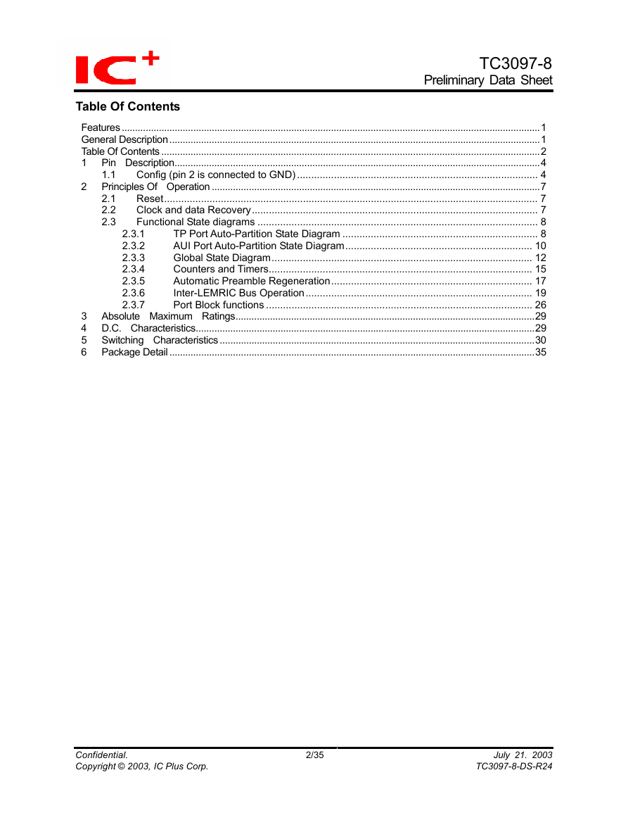
TC3097-8 Connection Diagram Config (pin 2 is connected to GND)
T
X
O
7
R
B
T
X
O
7
R
A
R
X
I
7
B
R
X
I
7
A
G
N
D
V
D
D
T
R
O
6
R
B
T
R
O
6
R
A
R
X
I
6
B
R
X
I
6
A
R
X
I
5
B
R
X
I
5
A
T
X
O
5
R
B
T
X
O
5
R
A
T
X
O
4
R
B
T
X
O
4
R
A
R
X
I
4
B
R
X
I
4
A
G
N
D
V
D
D
V
D
D
N
C
N
C
N
C
G
N
D
V
D
D
G
N
D
N
C
N
C
V
D
D
80
79
78
77
76
75
74
73
72
71
70
69
68
67
66
65
64
63
62
61
60
59
58
57
56
55
54
53
52
51
50
49
48
47
46
45
44
43
42
41
40
39
38
37
36
35
34
33
32
31
TXO3RA
TXO3RB
VDD
RXI3B
RXI3A
TXO2RA
TXO2RB
RXI2B
RXI2A
TX1B
TX1A
RX1B
RX1A
VDD
CD18
AGND
CD1A
CP1_0
VCO_I
AVDD
TC3097-8
100pin QFP
1 2
3 4 5 6 7 8 9 10 11 12 13 14 15 16 17 18 19 20 21 22 23 24 25 26 27 28 29 30
V
D
D
G
N
D
C
O
L
E
D
J
A
B
L
E
D
L
R
L
E
D
1
L
R
L
E
D
2
L
R
L
E
D
3
L
R
L
E
D
4
L
R
L
E
D
5
L
R
L
E
D
6
L
R
L
E
D
7
L
R
L
E
D
8
L
R
L
E
D
9
I
R
D
I
R
C
G
N
D
I
R
E
Z
A
C
K
O
A
C
K
I
A
C
T
N
Z
A
Y
X
N
Z
C
O
L
N
Z
R
E
S
E
T
Z
G
N
D
V
D
D
C
L
K
1
C
L
K
2
T
E
S
T
1
T
E
S
T
3
T
E
S
T
4
TXO8RA
TXO8RB
RXI8A
RXI8B
VDD
TXO9RA
TXO9RB
RXI9A
RXI9B
GND
PALED1
PALED2
PALED3
PALED4
PALED5
PALED6
PALED7
PALED8
PALED9
GND
81
82
83
84
85
86
87
88
89
90
91
92
93
94
95
96
97
98
99
100
Confidential.
Copyright © 2003, IC Plus Corp.
3/35
July 21. 2003
TC3097-8-DS-R24
�
TC3097-8
Preliminary Data Sheet
1
1.1
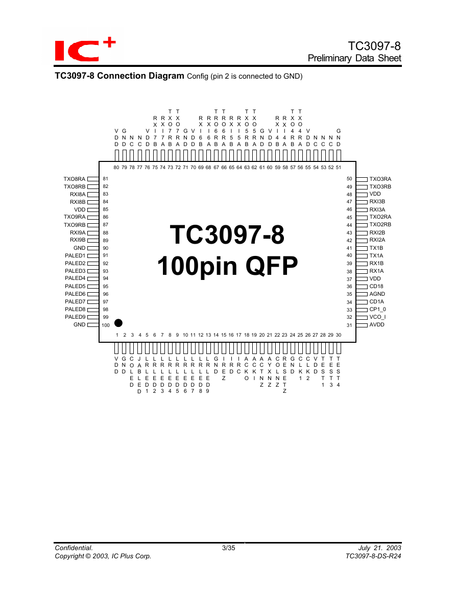
Pin Description
Config (pin 2 is connected to GND)
RXI2A to RXI9A
RXI2B to RXI9B
TXO2RA to
TXO9RA
TXO2RB to
TXO9RB
Pin No.
Symbol
Network Interface Pins
42, 46, 58,
64, 68, 74,
83, 88
43, 47, 59,
65, 69, 75,
84, 89
45, 50, 56,
62, 66, 72,
81, 86
44, 49, 57,
63, 67, 73,
82, 87
38
39
40
41
34
36
RX1A
RX1B
TX1A
TX1B
CD1A
CD1B
I/O
I
I
Description
Twisted-Pair Receive Input Positive
Twisted-Pair Receive Input Negative
O
Twisted-Pair Transmit Output Positive
O
Twisted-Pair Transmit Output Negative
AUI Receive Input Positive
I
I
AUI Receive Input Negative
O AUI Receive Output Positive
O AUI Receive Output Negative
I
I
AUI Collision Detect Input Positive
AUI Collision Detect Input Negative
Pin No.
Symbol
Power & Ground Pins
61, 71, 79 GND
VDD
48, 60, 70,
85
51, 90, 100 GND
37, 55, 76,
VDD
80
2, 14, 24 GND
VDD
1, 27
35
AGND
31
AVDD
Pin No.
Symbol
Inter-LEMRIC Bus Pins
19
ACKI
18
ACKO
I/O
Description
P Ground pins for TP port 1 to port 8 output pins.
P
Power pins for TP port 1 to TP port 8 output pins.
P Ground pin for internal digital circuit of this device.
P
Power pin for internal digital circuit of this device.
P Ground pins for digital output pins.
P
Power pins for digital output pins.
P Ground pin for PLL decoder internal circuit.
Power pin for PLL decoder internal circuit.
P
I/O
I
Description
ACKnowledge Input:
Input to the network port’s arbitration chain.
O ACKnowledge Output:
Output from the network port’s arbitration chain.
Confidential.
Copyright © 2003, IC Plus Corp.
4/35
July 21. 2003
TC3097-8-DS-R24
�
Pin No.
Symbol
Inter-LEMRIC Bus Pins
16
IRD
I/O
B,Z
15
IREZ
B,Z
17
IRC
B,Z
TC3097-8
Preliminary Data Sheet
Description
Inter-LEMRIC Data:
When asserted as an output this signal provides a serial data
stream in NRZ format.
This signal is asserted by a LEMRIC when it is receiving data
from one of its network segments. The default condition of this
signal is to be an input. In this state, it may be driven by other
devices on the Inter-LEMRIC bus.
Inter-LEMRIC Enable:
When asserted as an output this signal provides an activity-framing
enable for the serial data stream. The signal is asserted by a
LEMRIC when it is receiving data from one of its network segments.
The default condition of this signal is to be an input. In this state it
may be driven by other devices on the inter-LEMRIC bus.
Inter-LEMRIC Clock:
When asserted as an output this signal provides a clock signal for
the serial data stream. Data (XIRD) is changed on the falling edge of
the clock. The default condition of this signal is to be an input. When
an input, XIRD is sampled on the rising edge of the clock. In this
state it may be driven by other devices on the Inter-LEMRIC bus.
22
COLNZ
20
ACTNZ
21
AYXNZ
Symbol
Pin No.
LED Driver Pins
3
COLED
4
JABLED
B,Z Collision on Port N:
This denotes that a collision is occurring on the port receiving the
data packet (Port N). The default condition of this signal is to be
an input. In this state it may be driven by the other devices on the
Inter-LEMRIC bus.
B,Z Activity on Port N:
This is a bi-directional signal. The LEMRIC asserts this signal
when data or collision information is received from one of its
network segments. The LEMRIC senses this signal when this or
another LEMRIC in a multi-LEMRIC system is receiving data or
collision information.
B,Z Activity on ANY Port Excluding Port N:
This is a bi-directional signal. The LEMRIC asserts this signal
when a transmit collision is experienced or multiple ports have
active collisions on their network segments.
The LEMRIC senses this signal when this LEMRIC or other LEMRICs
in a multi-LEMRIC system are experiencing transmission collision or
multiple ports have active collisions on their network segments.
I/O
Description
O Global Collision LED (Active-Low):
This CMOS output indicates the status of the LEMRIC's any
collision activity.
O Global Jabber LED (Active-Low):
This CMOS output indicates when the LEMRIC's watchdog timer
begins to jab and stays active until end of the unjab wait period.
Confidential.
Copyright © 2003, IC Plus Corp.
5/35
July 21. 2003
TC3097-8-DS-R24
�
Symbol
Pin No.
LED Driver Pins
6-13
LRLED2 to
LRLED9
5
LRLED1
91-99
PALED1 to
PALED9
Symbol
Pin No.
TEST Support Pins
28
29
30
TEST1
TEST3
TEST4
Pin No.
Symbol
RESET & CLOCK Pins
23
RESETZ
CLK1
CLK2
25
26
Symbol
Pin No.
Decoder Filer Pins
33
CP1_O
VCO_I
32
Confidential.
Copyright © 2003, IC Plus Corp.
TC3097-8
Preliminary Data Sheet
Description
Link/Receive LED (active-Low):
This CMOS output goes active when the link integrity test is pass
on LEMRIC's TP port network segment and blinks when this
device is receiving from its link passing TP port segment.
I/O
O
O AUI Receive LED (Active-Low):
This CMOS output is powered on active and blinking when this
device is receiving from its AUI port network segment.
O Port Partition Jabber LED (Active-Low):
This CMOS output goes active when the LEMRIC's network
connection port is partitioned from its network segment and then
goes inactive when its network connection port is reconnection
from its network segment.
I/O
B
I/O
I
I
O
I/O
I
I
Description
These pins are used to facilitate device testing. When not in test
mode, these pins should be left open. [Note:] Pins TEST3 and
TEST4 can be used to modify the build in 10BASE-T operation.
TEST1 can be used to configure LED display mode (ICPLUS or
AMD compatible mode). Refer to port Block Function section for
more details.
Description
Optional device Reset. A low on this pin causes the device to
reset. RESET must be high for normal operation, when not used,
please leave open.
System Clock. 20 MHz, 50% nominal, 40/60% worst case, duty
cycle. The worst-case frequency tolerance and duty cycle limit the
range over which the LEMRIC will operate correctly. However,
since this clock is used for Manchester data transmission, jitter
performance will degrade if clock sources with relatively large
tolerances are used.
Description
Phase Lock Loop delay line external filter. This pin should be
connected correctly with a capacitor to AVDD or causing the
analog PLL of the device to be failed.
Phase Lock Loop VCO external filter. This pin should be
connected correctly with a RC filter circuit to AVDD or causing the
analog PLL of the device to be failed.
6/35
July 21. 2003
TC3097-8-DS-R24
�
TC3097-8
Preliminary Data Sheet
Reset
2 Principles Of Operation
2.1
The LEMRIC resets when XRESETZ (pin 25) is pulsed low. While reset, the LEMRIC ignores all energy
and collision inputs, unjabs all ports, and initializes all timers, counters, and state machines. At the end of
reset (XRESETZ goes high), all the LEDs are turned off and the XLRLED1 is turned on.
The minimum XRESETZ low pulse is one second to let the power on LED test visually distinguishable.
The LEMRIC is fully operational when it exits reset.
Clock and data Recovery
2.2
The clock and data recovery circuit (Manchester decoder) is a linear circuit, which it recovers the NRZ
data and clock from the Manchester encoded serial data stream. Data from the active port is routed to
the decoder and the recovered data is written into the FIFO.
Manchester
Data
NRZ
Data
NRZ
Clock
1 0 1 0 0
1 1 0 1 0 1 1
Figure 1. Manchester Data - NRZ Data Relationship
Confidential.
Copyright © 2003, IC Plus Corp.
7/35
July 21. 2003
TC3097-8-DS-R24
�
TC3097-8
Preliminary Data Sheet
Functional State diagrams
TP Port Auto-Partition State Diagram
2.3
The following state diagrams describe the auto-partition and global state machines implemented in the
LEMRIC. The notation and variables used in each diagram are described below.
2.3.1
A partitioning state machine is implemented for each TP port. Individual Tw5 and Tw6 timers and collision
counters are implemented for each state machine.
2.3.1.1 State Diagram Notation and Variables.
=
&
+
Assign the right side constant or expression result to the left side variable.
Logical ”AND” operator.
Logical ”OR” operator when used in a state-exiting expression. Arithmetic addition
when used otherwise.
Group term for logical evaluation.
Number identifier for the particular TP port.
Values: Integers from 1 to 8
Consecutive collision count for TP port X.
Values: Integers from 0 to 31
{[term]}
X
CC(X)
TEN(X)
Datain(X)
DIPresent(X) Carrier from the MAU on TP port X.
Values: Idle-Port carrier is not active.
Active-Port carrier is active.
TP port X carrier to the global state machine.
Values: Idle-Port carrier has been gated off by the partition state machine.
DIPresent(X)-Port carrier is passed on to the global state machine.
Status of transmission to the MAU on TP port X.
Values: Idle-Not transmitting to the port MAU.
Active-Transmitting to the port MAU.
Inter-LEMRIC that is Port N or Port M collision.
Values: Idle-/COLN is not active.
Active-/COLN is active.
Inter-LEMRIC that is not Port N or Port M collision.
Values: Idle-/ANYXN is not active.
Active-/ANYXN is active.
Enable Tw5 initializes and starts the PORT Tw5 timer. Tw5Done indicates that the timer
has expired.
Enable Tw6 initializes and starts the port Tw6 timer. /Tw6Done indicates that the timer is
running. Tw6Done indicates that the timer has expired.
/ANYXN
/COLN
Tw5
Tw6
Confidential.
Copyright © 2003, IC Plus Corp.
8/35
July 21. 2003
TC3097-8-DS-R24
�


 2023年江西萍乡中考道德与法治真题及答案.doc
 2012年重庆南川中考生物真题及答案.doc
 2013年江西师范大学地理学综合及文艺理论基础考研真题.doc
 2020年四川甘孜小升初语文真题及答案I卷.doc
 2020年注册岩土工程师专业基础考试真题及答案.doc
 2023-2024学年福建省厦门市九年级上学期数学月考试题及答案.doc
 2021-2022学年辽宁省沈阳市大东区九年级上学期语文期末试题及答案.doc
 2022-2023学年北京东城区初三第一学期物理期末试卷及答案.doc
 2018上半年江西教师资格初中地理学科知识与教学能力真题及答案.doc
 2012年河北国家公务员申论考试真题及答案-省级.doc
 2020-2021学年江苏省扬州市江都区邵樊片九年级上学期数学第一次质量检测试题及答案.doc
 2022下半年黑龙江教师资格证中学综合素质真题及答案.doc