AN-135
802.1Q Tag Based and Port Based VLAN
Function and Setting in KSZ8995M/MA
Introduction
This document will discuss IEEE802.1Q tag-based VLAN and port-based VLAN setup for the KSZ8995M/MA
devices. The reader should use this design note in conjunction with the datasheet which can be found at:
http://www.micrel.com/page.do?page=product-info/fastether_sw_man.jsp.
VLAN Overview
Virtual LANs (VLANs) consist of a logical independent workgroup operating within a physical network. These
workgroups behave as independent unique networks. The VLANs are defined by logical boundaries between
workgroups.
VLANs can be grouped by applications or functions. For example, the IT manager can define one VLAN for a
multimedia application and another for an e-mail application. Alternately, it can have one VLAN for its Engineering
Department, another for its Marketing Department, another for its Accounting Department, and so on.
As these examples show, VLANs offers unparalleled flexibility to ensure the best possible performance of the
network. The intent of this design note is to serve as a basic guide for using the Micrel KSZ8995M/MA in a VLAN
application.
IEEE 802.1Q VLAN
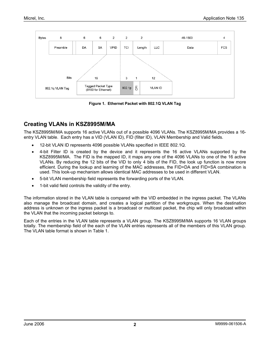
The KSZ8995M/MA supports the IEEE 802.1Q specification for “tagged” frames. The IEEE specification defines a
format of the frame in the network environment. An additional 4-octet header (or “tag”) is inserted in a frame after
the source MAC address and before the frame type. 12 bits of the tag are used to define the VLAN ID.
When packets pass through the KSZ8995M/MA, the device will look in each of the VLAN, static MAC and
dynamic MAC tables for an appropriate forwarding part. If the packet satisfies the necessary condition of the
forwarding conditions, then the packet will then be forwarded to the destination port. See the Figure 1 for tagged
frame format.
Micrel Inc. • 2180 Fortune Drive • San Jose, CA 95131 • USA • tel +1 (408) 944-0800 • fax + 1 (408) 474-1000 • http://www.micrel.com
June 2006
M9999-061506-A
�
Micrel, Inc.
Application Note 135
Figure 1. Ethernet Packet with 802.1Q VLAN Tag
Creating VLANs in KSZ8995M/MA
The KSZ8995M/MA supports 16 active VLANs out of a possible 4096 VLANs. The KSZ8995M/MA provides a 16-
entry VLAN table. Each entry has a VID (VLAN ID), FID (filter ID), VLAN Membership and Valid fields.
• 12-bit VLAN ID represents 4096 possible VLANs specified in IEEE 802.1Q.
• 4-bit Filter ID is created by the device and it represents the 16 active VLANs supported by the
KSZ8995M/MA. The FID is the mapped ID, it maps any one of the 4096 VLANs to one of the 16 active
VLANs. By reducing the 12 bits of the VID to only 4 bits of the FID, the look up function is now more
efficient. During the lookup and learning of the MAC addresses, the FID+DA and FID+SA combination is
used. This look-up mechanism allows identical MAC addresses to be used in different VLAN.
• 5-bit VLAN membership field represents the forwarding ports of the VLAN.
• 1-bit valid field controls the validity of the entry.
The information stored in the VLAN table is compared with the VID embedded in the ingress packet. The VLANs
also manage the broadcast domain, and creates a logical partition of the workgroups. When the destination
address is unknown or the ingress packet is a broadcast or multicast packet, the chip will only broadcast within
the VLAN that the incoming packet belongs to.
Each of the entries in the VLAN table represents a VLAN group. The KSZ8995M/MA supports 16 VLAN groups
totally. The membership field of the each of the VLAN entries represents all of the members of this VLAN group.
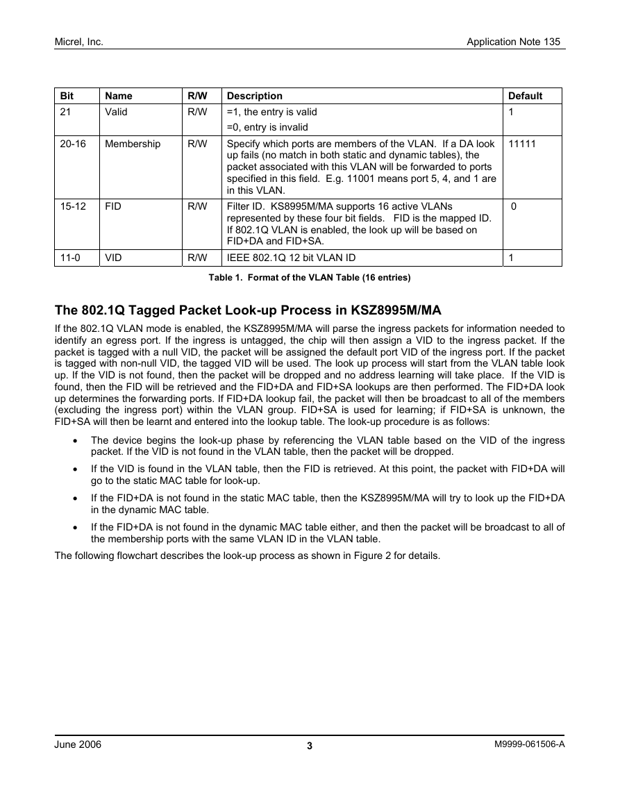
The VLAN table format is shown in Table 1.
June 2006
2
M9999-061506-A
�
Micrel, Inc.
Bit
21
Name
Valid
R/W
R/W
20-16 Membership
R/W
15-12
FID
11-0
VID
R/W
R/W
Application Note 135
Description
=1, the entry is valid
=0, entry is invalid
Specify which ports are members of the VLAN. If a DA look
up fails (no match in both static and dynamic tables), the
packet associated with this VLAN will be forwarded to ports
specified in this field. E.g. 11001 means port 5, 4, and 1 are
in this VLAN.
Filter ID. KS8995M/MA supports 16 active VLANs
represented by these four bit fields. FID is the mapped ID.
If 802.1Q VLAN is enabled, the look up will be based on
FID+DA and FID+SA.
IEEE 802.1Q 12 bit VLAN ID
Default
1
11111
0
1
Table 1. Format of the VLAN Table (16 entries)
The 802.1Q Tagged Packet Look-up Process in KSZ8995M/MA
If the 802.1Q VLAN mode is enabled, the KSZ8995M/MA will parse the ingress packets for information needed to
identify an egress port. If the ingress is untagged, the chip will then assign a VID to the ingress packet. If the
packet is tagged with a null VID, the packet will be assigned the default port VID of the ingress port. If the packet
is tagged with non-null VID, the tagged VID will be used. The look up process will start from the VLAN table look
up. If the VID is not found, then the packet will be dropped and no address learning will take place. If the VID is
found, then the FID will be retrieved and the FID+DA and FID+SA lookups are then performed. The FID+DA look
up determines the forwarding ports. If FID+DA lookup fail, the packet will then be broadcast to all of the members
(excluding the ingress port) within the VLAN group. FID+SA is used for learning; if FID+SA is unknown, the
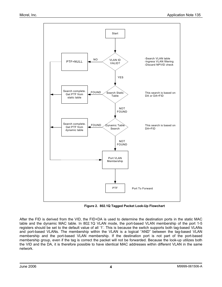
FID+SA will then be learnt and entered into the lookup table. The look-up procedure is as follows:
• The device begins the look-up phase by referencing the VLAN table based on the VID of the ingress
packet. If the VID is not found in the VLAN table, then the packet will be dropped.
If the VID is found in the VLAN table, then the FID is retrieved. At this point, the packet with FID+DA will
go to the static MAC table for look-up.
If the FID+DA is not found in the static MAC table, then the KSZ8995M/MA will try to look up the FID+DA
in the dynamic MAC table.
If the FID+DA is not found in the dynamic MAC table either, and then the packet will be broadcast to all of
the membership ports with the same VLAN ID in the VLAN table.
•
•
•
The following flowchart describes the look-up process as shown in Figure 2 for details.
June 2006
3
M9999-061506-A
�
Micrel, Inc.
Application Note 135
Start
PTF=NULL
NO
VLAN ID
VALID?
-Search VLAN table
-Ingress VLAN filtering
-Discard NPVID check
YES
Search complete.
Get PTF from
static table
FOUND
Search Static
Table
This search is based on
DA or DA+FID
NOT
FOUND
Search complete.
Get PTF from
dynamic table
FOUND
Dynamic Table
Search
This search is based on
DA+FID
NOT
FOUND
Port VLAN
Membership
PTF
Port To Forward
Figure 2. 802.1Q Tagged Packet Look-Up Flowchart
After the FID is derived from the VID, the FID+DA is used to determine the destination ports in the static MAC
table and the dynamic MAC table. In 802.1Q VLAN mode, the port-based VLAN membership of the port 1-5
registers should be set to the default value of all ‘1’. This is because the switch supports both tag-based VLANs
and port-based VLANs. The membership within the VLAN is a logical “AND” between the tag-based VLAN
membership and the port-based VLAN membership. If the destination port is not part of the port-based
membership group, even if the tag is correct the packet will not be forwarded. Because the look-up utilizes both
the VID and the DA, it is therefore possible to have identical MAC addresses within different VLAN in the same
network.
June 2006
4
M9999-061506-A
�
Micrel, Inc.
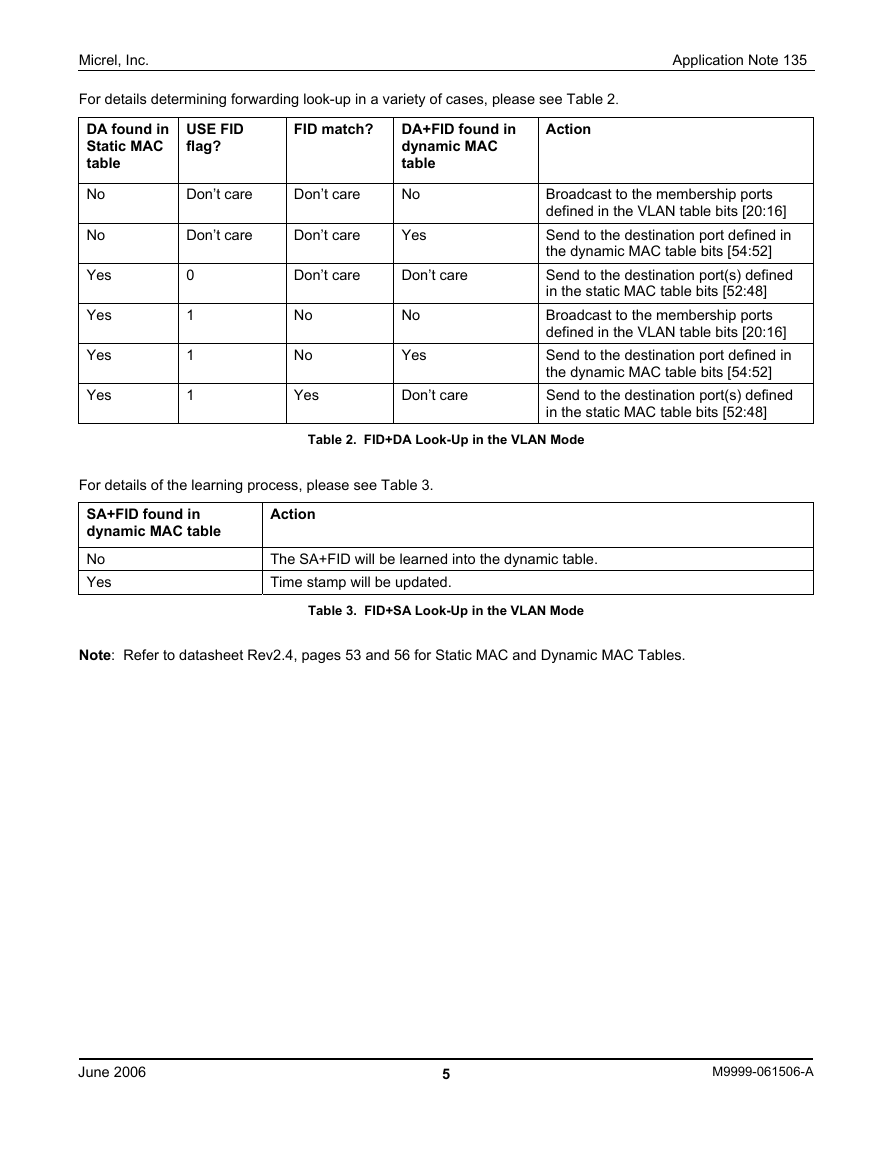
For details determining forwarding look-up in a variety of cases, please see Table 2.
DA found in
Static MAC
table
DA+FID found in
dynamic MAC
table
USE FID
flag?
FID match?
Action
Application Note 135
No
No
Yes
Yes
Yes
Yes
Don’t care
Don’t care
No
Don’t care
Don’t care
Yes
0
1
1
1
Don’t care
Don’t care
No
No
Yes
No
Yes
Don’t care
Broadcast to the membership ports
defined in the VLAN table bits [20:16]
Send to the destination port defined in
the dynamic MAC table bits [54:52]
Send to the destination port(s) defined
in the static MAC table bits [52:48]
Broadcast to the membership ports
defined in the VLAN table bits [20:16]
Send to the destination port defined in
the dynamic MAC table bits [54:52]
Send to the destination port(s) defined
in the static MAC table bits [52:48]
Table 2. FID+DA Look-Up in the VLAN Mode
For details of the learning process, please see Table 3.
SA+FID found in
dynamic MAC table
No
Yes
Action
The SA+FID will be learned into the dynamic table.
Time stamp will be updated.
Note: Refer to datasheet Rev2.4, pages 53 and 56 for Static MAC and Dynamic MAC Tables.
Table 3. FID+SA Look-Up in the VLAN Mode
June 2006
5
M9999-061506-A
�
Micrel, Inc.
Registers Associated with VLAN Configuration
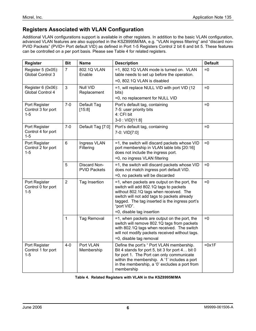
Additional VLAN configurations support is available in other registers. In addition to the basic VLAN configuration,
advanced VLAN features are also supported in the KSZ8995M/MA, e.g. “VLAN ingress filtering” and “discard non-
PVID Packets” (PVID= Port default VID) as defined in Port 1-5 Registers Control 2 bit 6 and bit 5. These features
can be controlled on a per port basis. Please see Table 4 for related registers.
Application Note 135
7-0
Default Tag [7:0] Port’s default tag, containing
7-0: VID[7:0]
Register
Register 5 (0x05):
Global Control 3
Bit
7
Name
802.1Q VLAN
Enable
Register 6 (0x06):
Global Control 4
3
Null VID
Replacement
7-0
Default Tag
[15:8]
Port Register
Control 3 for port
1-5
Port Register
Control 4 for port
1-5
Port Register
Control 2 for port
1-5
Port Register
Control 0 for port
1-5
6
5
2
Ingress VLAN
Filtering
Discard Non-
PVID Packets
Tag Insertion
1
Tag Removal
Description
=1, 802.1Q VLAN mode is turned on. VLAN
table needs to set up before the operation.
=0, 802.1Q VLAN is disabled
=1, will replace NULL VID with port VID (12
bits)
=0, no replacement for NULL VID
Port’s default tag, containing
7-5: user priority bits
4: CFI bit
3-0 : VID[11:8]
=1, the switch will discard packets whose VID
port membership in VLAN table bits [20:16]
does not include the ingress port.
=0, no ingress VLAN filtering
=1, the switch will discard packets whose VID
does not match ingress port default VID.
=0, no packets will be discarded
=1, when packets are output on the port, the
switch will add 802.1Q tags to packets
without 802.1Q tags when received. The
switch will not add tags to packets already
tagged. The tag inserted is the ingress port’s
“port VID”.
=0, disable tag insertion
=1, when packets are output on the port, the
switch will remove 802.1Q tags from packets
with 802.1Q tags when received. The switch
will not modify packets received without tags.
=0, disable tag removal
Define the port’s “ Port VLAN membership.
Bit 4 stands for port 5, bit 3 for port 4… bit 0
for port 1. The Port can only communicate
within the membership. A ‘1’ includes a port
in the membership, a ‘0’ excludes a port from
membership
Default
=0
=0
=0
=0
=0
=0
=0
=0
=0x1F
Port Register
Control 1 for port
1-5
4-0
Port VLAN
Membership
June 2006
Table 4. Related Registers with VLAN in the KSZ8995M/MA
6
M9999-061506-A
�
Micrel, Inc.
Steps for Creating Port-Based VLAN:
Application Note 135
1. Set Port 1-5 Registers Control 1, Port VLAN Membership bits [4-0] for port VLAN mask.
2. Confirm Register 5 Global Control 3, bit 7=0 (default) and 802.1Q VLAN is turned off.
3. For example, set up ports 1, 2, 3 and 5 for port-based VLAN 1, and set up ports 4 and 5 for port- based
VLAN 2. As VLAN 1 has overlap with VLAN 2 at port 5, the broadcast and multicast packets may cross
VLAN boundaries when port 5 is the ingress port. The setting of the membership field on the port 1-5
registers are set as follows:
• Set port 1, port 2 and port 3 Registers Control 1 bits [4-0] = (1, 0, 1, 1, 1) to the same value.
• Set Port 4 Register Control 1 bits [4-0] = (1, 1, 0, 0, 0).
• Set Port 5 Register Control 1 bits [4-0] = (1, 1, 1, 1, 1) for both port based VLAN 1 and VLAN 2. From
this setting of port 5, if broadcast and multicast packets come in from port 5, the packets will cross the
VLAN boundary to all ports excluding the ingress port 5.
When using port based VLANs, it is advised not to overlap the ports in the VLANs, as shown in the above
example. This will prevent VLAN traffic from crossing boundaries.
Steps for Creating 802.1Q Tag VLAN:
1. Set Register 5 Global Control 3 bit 7 to turn on the 802.1Q VLAN Enable.
2. Set Register 6 Global Control 4 bit 3 for null VID replacement using default VID if the tagged packet is null
VID.
3. Set Port 1-5 Register Control 3 and Control 4 for default tag of the ingress port when 802.1Q VLAN is
enabled and ingress packet is non-tag or null tag. Then the default tag and its value will be used in VLAN
table for look-up.
4. Set Port 1-5 Registers Control 2 bit 6 for ingress VLAN Filtering if it is required.
5. Set Port 1-5 Registers Control 2 bit 5 for Discard Non-PVID packets if it is required.
6.
If you want to add the default tag for the ingress packet with non-tag on the egress port, set Port 1-5
Register Control 0 bit 2 for tag insertion at the egress port.
7. When using 802.1Q VLAN mode look-up result, port 1-5 registers control 1 bits [4-0] of the port VLAN
membership should be in the default value.
8. Write the VID and FID of the VLAN group into the VLAN table.
For example:
• Port 1, 2, 3 and 5 are tag VLAN 1 (Write an entry with VID=1 FID=1 VLAN membership = (1, 0, 1, 1,
1) for port 1, 2, 3, and 5 in the VLAN table).
• Port 4, 5 are tag VLAN 2 (Write an entry with VID=2 FID=2 VLAN membership= (1, 1, 0, 0, 0) for port
4 and 5 in the VLAN table).
• Set default tag for VID
Set Port 1, 2, and 3 Registers Control 4 VID=1
Set Port 4 Register Control 4 VID=2
• Set tag insertion for port 5
Set Port 5 Register Control 0 bit 2=1 for tag insertion on egress port 5.
When packets are passed from ingress port 1, 2, or 3 then the egress port 5 will insert a tag with VID=1. When
packets are passed from ingress port 4 then the egress port 5 will insert a tag with VID=2. Usually, port 5 is
connected to a microprocessor which will recognize the VID of each packet. When port 5 sends back packets to
the ingress ports where the packet originated from, port 5 will segregate the traffic for VLAN 1 and VLAN 2. Since
the 8021.Q tag VLAN is based on the VID, and not based on the physical ports, the broadcast and multicast traffic
can not pass the VLAN boundaries.
June 2006
7
M9999-061506-A
�
Micrel, Inc.
Summary
The KSZ8995M/MA 5-port switch has very flexible VLAN function capabilities. It allows the customer to create a
large variety combination of VLAN groups by utilizing both port-based and 802.1Q based VLANs. In addition, the
unique lookup algorithm allows identical MAC addresses to coexist within the same network, making the
KSZ8995M/MA are very useful in isolating and segregating specific flows within the network.
Application Note 135
MICREL, INC. 2180 FORTUNE DRIVE SAN JOSE, CA 95131 USA
TEL +1 (408) 944-0800 FAX +1 (408) 474-1000 WEB http:/www.micrel.com
The information furnished by Micrel in this data sheet is believed to be accurate and reliable. However, no responsibility is assumed by Micrel
for its use. Micrel reserves the right to change circuitry and specifications at any time without notification to the customer.
Micrel Products are not designed or authorized for use as components in life support appliances, devices or systems where malfunction of a
product can reasonably be expected to result in personal injury. Life support devices or systems are devices or systems that (a) are intended
for surgical implant into the body or (b) support or sustain life, and whose failure to perform can be reasonably expected to result in a
significant injury to the user. A Purchaser’s use or sale of Micrel Products for use in life support appliances, devices or systems is a
Purchaser’s own risk and Purchaser agrees to fully indemnify Micrel for any damages resulting from such use or sale.
June 2006
© 2006 Micrel, Incorporated.
8
M9999-061506-A
�



 2023年江西萍乡中考道德与法治真题及答案.doc
 2012年重庆南川中考生物真题及答案.doc
 2013年江西师范大学地理学综合及文艺理论基础考研真题.doc
 2020年四川甘孜小升初语文真题及答案I卷.doc
 2020年注册岩土工程师专业基础考试真题及答案.doc
 2023-2024学年福建省厦门市九年级上学期数学月考试题及答案.doc
 2021-2022学年辽宁省沈阳市大东区九年级上学期语文期末试题及答案.doc
 2022-2023学年北京东城区初三第一学期物理期末试卷及答案.doc
 2018上半年江西教师资格初中地理学科知识与教学能力真题及答案.doc
 2012年河北国家公务员申论考试真题及答案-省级.doc
 2020-2021学年江苏省扬州市江都区邵樊片九年级上学期数学第一次质量检测试题及答案.doc
 2022下半年黑龙江教师资格证中学综合素质真题及答案.doc