RF TEST REPORT
Applicant ESPRESSIF SYSTEMS (SHANGHAI) PTE LTD
FCC ID
2AC7Z-ESPWROOM32D
Product Wi-Fi & Bluetooth Internet of Things Module
Brand
Model
WROOM
ESP-WROOM-32D
Report No. RXA1710-0352RF02
Issue Date December 8, 2017
TA Technology (Shanghai) Co., Ltd. tested the above equipment in accordance with the requirements in FCC
CFR47 Part 15C (2017). The test results show that the equipment tested is capable of demonstrating
compliance with the requirements as documented in this report.
Performed by: Xianqing Li
Approved by: Kai Xu
TA Technology (Shanghai) Co., Ltd.
No.145, Jintang Rd, Tangzhen Industry Park, Pudong Shanghai, China
TEL: +86-021-50791141/2/3
FAX: +86-021-50791141/2/3-8000
�
FCC RF Test Report Report No: RXA1710-0352RF02
Table of Contents
4.1
4.2
4.3
4.4
1 Test Laboratory ............................................................................................................................... 4
1.1 Notes of the Test Report ......................................................................................................... 4
Test facility .............................................................................................................................. 4
1.2
1.3
Testing Location ...................................................................................................................... 5
2 General Description of Equipment under Test ................................................................................ 6
3 Applied Standards .......................................................................................................................... 7
4
Information about the FHSS characteristics ................................................................................... 8
Pseudorandom Frequency Hopping Sequence ....................................................................... 8
Equal Hopping Frequency Use ............................................................................................... 9
System Receiver Input Bandwidth .......................................................................................... 9
Test Configuration ................................................................................................................... 9
5 Test Case Results ........................................................................................................................ 10
Peak Power Output –Conducted ........................................................................................... 10
5.1
5.2 Occupied Bandwidth (20dB) .................................................................................................. 12
Frequency Separation ........................................................................................................... 16
5.3
Time of Occupancy (Dwell Time) ........................................................................................... 18
5.4
5.5
Band Edge Compliance ........................................................................................................ 20
5.6
Spurious Radiated Emissions in the Restricted Band ........................................................... 23
5.7 Number of hopping Frequency .............................................................................................. 26
5.8
Spurious RF Conducted Emissions ....................................................................................... 28
5.9 Radiates Emission ................................................................................................................ 31
5.10 Conducted Emission ............................................................................................................. 41
6 Main Test Instruments .................................................................................................................. 43
ANNEX A: EUT Appearance and Test Setup ....................................................................................... 44
A.1 EUT Appearance ................................................................................................................... 44
A.2 Test Setup ............................................................................................................................. 45
TA Technology (Shanghai) Co., Ltd. TA-MB-04-004R Page 2 of 46
This report shall not be reproduced except in full, without the written approval of TA Technology (Shanghai) Co., Ltd.
�
FCC RF Test Report Report No: RXA1710-0352RF02
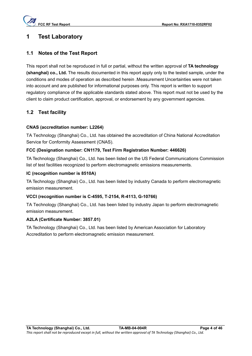
Summary of Measurement Results
Number Summary of measurements of results
1
2
3
4
5
6
7
8
9
10
Peak Power Output -Conducted
Occupied Bandwidth (20dB)
Frequency Separation
Time of Occupancy (Dwell Time)
Band Edge Compliance
Spurious Radiated Emissions in the
restricted band
Number of Hopping Frequency
Spurious RF Conducted Emissions
Radiates Emission
AC Power Line Conducted Emission
Clause in FCC rules
15.247(b)(1)
15.247(a)(1)
15.247(a)(1)
15.247(a)(1)(iii)
15.247(d)
Verdict
PASS
PASS
PASS
PASS
PASS
15.247(d),15.205,15.209 PASS
PASS
15.247(a)(1)(iii)
PASS
15.247(d)
15.247(d),15.205,15.209 PASS
15.207
PASS
Date of Testing: November 1, 2017~ December 7, 2017
TA Technology (Shanghai) Co., Ltd. TA-MB-04-004R Page 3 of 46
This report shall not be reproduced except in full, without the written approval of TA Technology (Shanghai) Co., Ltd.
�
FCC RF Test Report Report No: RXA1710-0352RF02
1 Test Laboratory
1.1 Notes of the Test Report
This report shall not be reproduced in full or partial, without the written approval of TA technology
(shanghai) co., Ltd. The results documented in this report apply only to the tested sample, under the
conditions and modes of operation as described herein .Measurement Uncertainties were not taken
into account and are published for informational purposes only. This report is written to support
regulatory compliance of the applicable standards stated above. This report must not be used by the
client to claim product certification, approval, or endorsement by any government agencies.
1.2 Test facility
CNAS (accreditation number: L2264)
TA Technology (Shanghai) Co., Ltd. has obtained the accreditation of China National Accreditation
Service for Conformity Assessment (CNAS).
FCC (Designation number: CN1179, Test Firm Registration Number: 446626)
TA Technology (Shanghai) Co., Ltd. has been listed on the US Federal Communications Commission
list of test facilities recognized to perform electromagnetic emissions measurements.
IC (recognition number is 8510A)
TA Technology (Shanghai) Co., Ltd. has been listed by industry Canada to perform electromagnetic
emission measurement.
VCCI (recognition number is C-4595, T-2154, R-4113, G-10766)
TA Technology (Shanghai) Co., Ltd. has been listed by industry Japan to perform electromagnetic
emission measurement.
A2LA (Certificate Number: 3857.01)
TA Technology (Shanghai) Co., Ltd. has been listed by American Association for Laboratory
Accreditation to perform electromagnetic emission measurement.
TA Technology (Shanghai) Co., Ltd. TA-MB-04-004R Page 4 of 46
This report shall not be reproduced except in full, without the written approval of TA Technology (Shanghai) Co., Ltd.
�
FCC RF Test Report Report No: RXA1710-0352RF02
1.3 Testing Location
Company:
TA Technology (Shanghai) Co., Ltd.
Address:
No.145, Jintang Rd, Tangzhen Industry Park, Pudong Shanghai, China
City:
Post code:
Country:
Shanghai
201201
P. R. China
Contact:
Xu Kai
Telephone:
+86-021-50791141/2/3
Fax:
Website:
E-mail:
+86-021-50791141/2/3-8000
http://www.ta-shanghai.com
xukai@ta-shanghai.com
TA Technology (Shanghai) Co., Ltd. TA-MB-04-004R Page 5 of 46
This report shall not be reproduced except in full, without the written approval of TA Technology (Shanghai) Co., Ltd.
�
FCC RF Test Report Report No: RXA1710-0352RF02
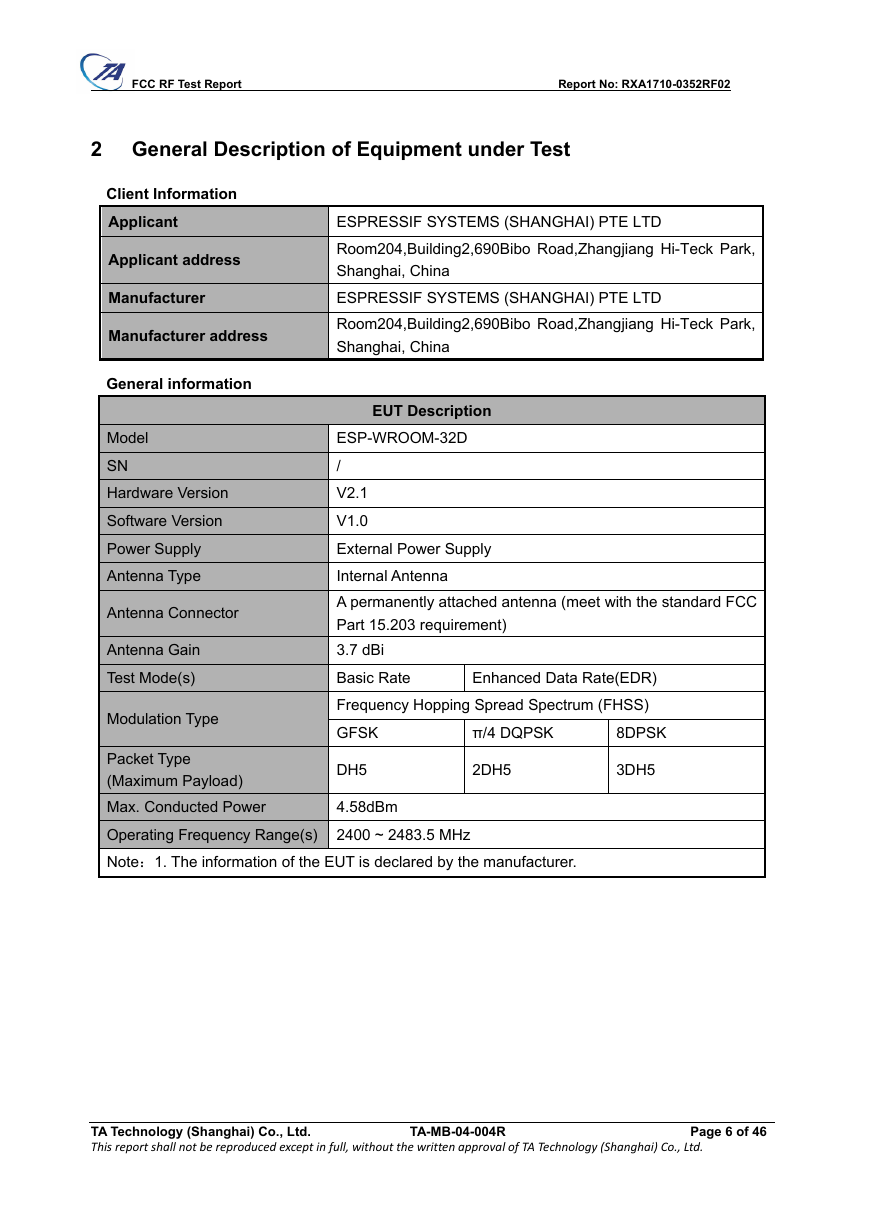
2 General Description of Equipment under Test
Client Information
Applicant
Applicant address
Manufacturer
Manufacturer address
General information
Model
SN
Hardware Version
Software Version
Power Supply
Antenna Type
Antenna Connector
Antenna Gain
Test Mode(s)
Modulation Type
ESPRESSIF SYSTEMS (SHANGHAI) PTE LTD
Room204,Building2,690Bibo Road,Zhangjiang Hi-Teck Park,
Shanghai, China
ESPRESSIF SYSTEMS (SHANGHAI) PTE LTD
Room204,Building2,690Bibo Road,Zhangjiang Hi-Teck Park,
Shanghai, China
EUT Description
ESP-WROOM-32D
/
V2.1
V1.0
External Power Supply
Internal Antenna
A permanently attached antenna (meet with the standard FCC
Part 15.203 requirement)
3.7 dBi
Basic Rate
Enhanced Data Rate(EDR)
Frequency Hopping Spread Spectrum (FHSS)
GFSK
π/4 DQPSK
8DPSK
DH5
Packet Type
(Maximum Payload)
Max. Conducted Power
Operating Frequency Range(s) 2400 ~ 2483.5 MHz
Note:1. The information of the EUT is declared by the manufacturer.
4.58dBm
2DH5
3DH5
TA Technology (Shanghai) Co., Ltd. TA-MB-04-004R Page 6 of 46
This report shall not be reproduced except in full, without the written approval of TA Technology (Shanghai) Co., Ltd.
�
FCC RF Test Report Report No: RXA1710-0352RF02
3 Applied Standards
According to the specifications of the manufacturer, it must comply with the requirements of the
following standards:
Test standards
‧ FCC CFR47 Part 15C (2017) Radio Frequency Devices
‧ ANSI C63.10 (2013)
‧ DA00-705 Filing and Frequency Measurement Guidelines For Frequency Hopping Spread
Spectrum System (2000).
TA Technology (Shanghai) Co., Ltd. TA-MB-04-004R Page 7 of 46
This report shall not be reproduced except in full, without the written approval of TA Technology (Shanghai) Co., Ltd.
�
FCC RF Test Report Report No: RXA1710-0352RF02
4
Information about the FHSS characteristics
4.1 Pseudorandom Frequency Hopping Sequence
Frequency Hopping Systems. A spread spectrum system in which the carrier is modulated with the
coded information in a conventional manner causing a conventional spreading of the RF energy
about the frequency carrier. The frequency of the carrier is not fixed but changes at fixed intervals
under the direction of a coded sequence. The wide RF bandwidth needed by such a system is not
required by spreading of the RF energy about the carrier but rather to accommodate the range of
frequencies to which the carrier frequency can hop. The test of a frequency hopping system is that
the near term distribution of hops appears random, the long term distribution appears evenly
distributed over the hop set, and sequential hops are randomly distributed in both direction and
magnitude of change in the hop set.
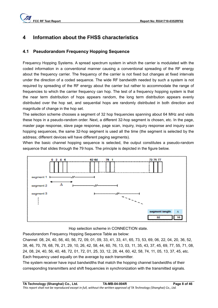
The selection scheme chooses a segment of 32 hop frequencies spanning about 64 MHz and visits
these hops in a pseudo-random order. Next, a different 32-hop segment is chosen, etc. In the page,
master page response, slave page response, page scan, inquiry, inquiry response and inquiry scan
hopping sequences, the same 32-hop segment is used all the time (the segment is selected by the
address; different devices will have different paging segments).
When the basic channel hopping sequence is selected, the output constitutes a pseudo-random
sequence that slides through the 79 hops. The principle is depicted in the figure below.
Hop selection scheme in CONNECTION state.
Pseudorandom Frequency Hopping Sequence Table as below:
Channel: 08, 24, 40, 56, 40, 56, 72, 09, 01, 09, 33, 41, 33, 41, 65, 73, 53, 69, 06, 22, 04, 20, 36, 52,
38, 46, 70, 78, 68, 76, 21, 29, 10, 26, 42, 58, 44, 60, 76, 13, 03, 11, 35, 43, 37, 45, 69, 77, 55, 71, 08,
24, 08, 24, 40, 56, 40, 48, 72, 01, 72, 01, 25, 33, 12, 28, 44, 60, 42, 58, 74, 11, 05, 13, 37, 45, etc.
Each frequency used equally on the average by each transmitter.
The system receiver have input bandwidths that match the hopping channel bandwidths of their
corresponding transmitters and shift frequencies in synchronization with the transmitted signals.
TA Technology (Shanghai) Co., Ltd. TA-MB-04-004R Page 8 of 46
This report shall not be reproduced except in full, without the written approval of TA Technology (Shanghai) Co., Ltd.
�



 2023年江西萍乡中考道德与法治真题及答案.doc
 2012年重庆南川中考生物真题及答案.doc
 2013年江西师范大学地理学综合及文艺理论基础考研真题.doc
 2020年四川甘孜小升初语文真题及答案I卷.doc
 2020年注册岩土工程师专业基础考试真题及答案.doc
 2023-2024学年福建省厦门市九年级上学期数学月考试题及答案.doc
 2021-2022学年辽宁省沈阳市大东区九年级上学期语文期末试题及答案.doc
 2022-2023学年北京东城区初三第一学期物理期末试卷及答案.doc
 2018上半年江西教师资格初中地理学科知识与教学能力真题及答案.doc
 2012年河北国家公务员申论考试真题及答案-省级.doc
 2020-2021学年江苏省扬州市江都区邵樊片九年级上学期数学第一次质量检测试题及答案.doc
 2022下半年黑龙江教师资格证中学综合素质真题及答案.doc