4994
IEEE TRANSACTIONS ON INDUSTRIAL ELECTRONICS, VOL. 64, NO. 6, JUNE 2017
A Novel Disturbance Estimation Scheme for
Formation Control of Ocean Surface Vessels
Bing Xiao, Xuebo Yang, and Xing Huo
Abstract—To achieve high-accuracy formation control of
multiple ocean surface vessels, the external disturbance
acting on each vessel should be accommodated. In this pa-
per, a novel disturbance estimation scheme is presented
to solve this problem, and to provide the future formation
controller design with precise estimation information. This
approach is developed in the theoretical framework of a ter-
minal sliding mode observer. The proposed observer is able
to precisely estimate external disturbance after finite time.
It is shown by Lyapunov stability analysis that the estima-
tion error for external disturbance will converge to zero after
finite time. A fast and precise estimation for external distur-
bance is achieved. Numerical example is further presented
to validate the effectiveness of the developed disturbance
estimation approach.
Index Terms—Disturbance estimation, finite-time stable
(FTS), nonlinear observer, ocean surface vessels.
I. INTRODUCTION
O VER the past three decades, underwater vehicles or sur-
face vessels are widely applied to industrial production
such as ocean exploration, oil harvesting, transportations, etc.
Moreover, the demand of autonomous operation of those vehi-
cles has been increased due to efficiency requirement. To meet
this demand, the problem of autonomous controller design is
a key challenge that needs to be solved. Therefore, this issue
has attracted more and more attention in theoretical area and in
practical engineering [1].
In practice, some industrial tasks would not be accomplished
by using a single underwater vehicle or surface vessel. Some-
times, multiple vehicles/vessels are needed. As a result, for-
mation, cooperative, or synchronization control [2] should be
carried out [3], [4]. For instance, the problem of path following
of underactuated surface vessels was studied in [5]. In [6], a
controller with simple structure was designed for controlling of
Manuscript received May 23, 2016; revised August 10, 2016; accepted
October 3, 2016. Date of publication October 27, 2016; date of cur-
rent version May 10, 2017. This work was supported in part by the
National Natural Science Foundation of China under Grant 61403102,
Grant 61503035, and Grant 61573071, and in part by a China Post-
doctoral Science Foundation funded project under Grant 2016M590456.
(Corresponding author: Xuebo Yang.)
B. Xiao and X. Huo are with the College of Engineering, Bohai Univer-
sity, Jinzhou 121013, China (e-mail: bxiaobing@gmail.com; hmyi888@
163.com).
X. Yang is with the Research Institute of Intelligent Control and Sys-
tems, Harbin Institute of Technology, Harbin 150080, China (e-mail:
xueboyang@hit.edu.cn).
Color versions of one or more of the figures in this paper are available
online at http://ieeexplore.ieee.org.
Digital Object Identifier 10.1109/TIE.2016.2622219
multiple underwater vehicles in formation. In another work [7],
the problem of coordinated path-following control was inves-
tigated. With angle constraints and system fault, a finite-time
formation controller was presented in [8]. In the presence of
communication delays, autonomous formation control of un-
derwater vehicles was studied in [9]. The problem of formation
control in face of time delays was further addressed in [10]. In
[11], a nonlinear formation keeping approach was developed for
multiple underwater vehicles. In addition to these results and in-
spired by modern control theory, many formation control design
schemes were also proposed by using nonlinear control tech-
niques such as adaptive control [12], [13], sliding mode control
[14], passivity-based control [15], and Lyapunov stability-based
control [16], [17].
It should be stressed that trajectory tracking should be per-
formed no matter for a single surface vessel or even formation
of surface vessels. As a consequence, trajectory tracking au-
tonomous control should be carried out in the application of un-
derwater vehicles or underactuated surface vessels. To achieve
this, an output feedback tracking control scheme was reported
in [18] and [19]. In another work [20], the trajectory tracking
control problem was solved by using the theoretical framework
of event triggered technology. In [21], a novel controller de-
signed by using sliding mode control was adopted to achieve
high-accuracy tracking control for surface vessels. In [22], a
tracking controller was designed by using a linear algebra ap-
proach. A global tracking control law was presented for un-
deractuated ships in [23]. The problem of input and velocity
constraint was addressed. Another global tracking scheme was
presented in [24] with input constraint considered. When the ma-
rine vehicles were under the effect of external disturbance and
input saturation, another tracking controller design was reported
in [25].
In the tracking controller design for ocean surface ves-
sels, external disturbance or uncertain dynamics acting on the
systems is one of the key challenges that need to be solved.
Otherwise, it will inevitably deteriorate the formation control
performance and even make the tracking system instability. As
a result, the problem of trajectory tracking control design in the
presence of external disturbance has attracted more and more
attention [26]. In [27], a sliding mode-based controller was de-
signed to achieve trajectory control. The resulted tracking per-
formance was with great robustness to external disturbance.
In [28], a model predictive-based controller was developed to
achieve tracking control with disturbance compensated. An al-
ternative solution to this problem is to estimate external distur-
0278-0046 © 2016 IEEE. Personal use is permitted, but republication/redistribution requires IEEE permission.
See http://www.ieee.org/publications standards/publications/rights/index.html for more information.
�
XIAO et al.: NOVEL DISTURBANCE ESTIMATION SCHEME FOR FORMATION CONTROL OF OCEAN SURFACE VESSELS
4995
bance first, and then to design trajectory tracking control law
by the estimated information with the external disturbance ac-
commodated. For this, one of the widely applied techniques to
estimate external disturbance or uncertain dynamics is neu-
ral network. Neural network is utilized to approximate dis-
turbance or system uncertainties, and then an approximated
value-based controller was synthesized to achieve high-accuracy
tracking control. The investigations using this methodology can
be observed in [29], [30], and references therein. Although this
methodology is an effective way to handle disturbance, asymp-
totic stability of the closed-loop tracking system would not be
achieved. This is because there has approximation error for
neural networks. Therefore, the disturbance cannot be precisely
estimated and compensated.
To precisely estimate disturbance/uncertain dynamics acting
on surface vessels, an alternative solution is to design nonlinear
observers [31]. Although the last two decades have witnessed
significant development in a disturbance observer for linear and
even nonlinear systems [32]–[34], few investigations are avail-
able for surface vessels. In [35], the disturbance, i.e., unknown
ocean currents, was estimated by an observer, and the track-
ing system was guaranteed to be exponentially stable by using
the synthesized estimation-based controller. In [36], a nonlinear
disturbance observer was presented for tracking control design
of surface vessel. Asymptotic estimation of disturbance was
guaranteed. In [37], another disturbance observer-based trajec-
tory tracking control approach was developed for fully actuated
surface vehicles. More specifically, the incorporated observer is
with finite-time convergence. In [38], another nonlinear distur-
bance observer was designed to estimate unknown ocean distur-
bances. Although a fast estimation of disturbance was achieved,
the estimation error can be governed only to a small ball contain-
ing zero. In [39], a reduced-order extended state observer (ESO)
was reported to identify the unknown ocean disturbance. In a
more recent study [40], another ESO was available for robust
steering control of marine surface vessels.
Although the preceding disturbance observers are able to pro-
vide the tracking controller design of surface vessels with high-
accuracy estimation information of disturbance, almost all of
them are designed using a stability analysis that can only guar-
antee the disturbance estimation error converging to zero with
an infinite settling time. Obviously, the infinite settling time
criterion is not an option during critical phases of the tasks.
Suppose that the disturbance acting on the surface vessels can-
not be estimated within finite time. Then, the corresponding
observer-based control would not compensate for the external
disturbance in finite time, and the external disturbance will result
in deterioration of control performance. To the best knowledge
of the authors, currently, only the work in [37] can provide a
finite-time disturbance estimation for surface vessels. With a
view to handling this drawback, this work will present a novel
external disturbance estimation approach for the formation con-
troller design of multiple ocean surface vessels. To achieve such
objective, a terminal sliding mode observer-based estimation
law will be presented for each agent of the formation. The main
contributions of this study are as follows.
1) The external disturbance acting on the surface vessels can
be estimated by the proposed observer. In comparison
with the existing disturbance observer design for surface
vessels such as [36], the estimation error obtained from
the proposed observer can be governed to be finite-time
stable (FTS). A fast and precise estimation of disturbance
can thus be achieved.
2) In comparison with the finite-time disturbance observer
(FTDO) in [37], the proposed disturbance estimation ap-
proach can be viewed as a parallel solution to the problem
of disturbance observer design with finite-time conver-
gence. Moreover, the proposed methodology can elim-
inate the assumption used in [37] that the derivative of
external disturbance should exist.
The reminder of this paper is organized as follows. The prob-
lme statement is presented in Section II with mathematical
mode of formation control of ocean surface vessels given. In
Section III, the main result of distrubance estimation appraoch
is presented. The effectiveness of the estimation approach is val-
idated by using simulation results in Section IV, and this paper
ends with conclusions summarized in Section V.
II. PROBLEM STATEMENT
A. Preliminaries
The notation used in this study is fairly standard. Let
and + denote the set of real and positive real numbers,
respectively. m×n represents the set of m by n real matrices.
λmax(·) is the maximum eignvalue of a matrix. For a given
vector, ||·|| denotes the vector Euclidean norm; for a given
matrix, ||·|| represents its induced Euclidean norm. For a vector
a = [ a1 a2 . . . am ]T ∈ m and a positive scalar ∈ ,
sgn(a) = [ sgn(a1) sgn(a2) . . . sgn(am ) ]T ∈ m and a
= [|a1|sgn(a1) |a2|sgn(a2) . . .
|am|sgn(am ) ]T ∈ m
are defined, where sgn(·) is the signum function.
For the following system:
˙x(t) = f(x(t), t), x(0) = x0, f(x0, 0) = 0, x ∈ n
(1)
with f : D × + → n being continuous on an open neighbor-
hood D ⊂ n of the origin x = 0, the definition of finite-time
stability is recalled as follows.
if
Definition 1: [41]. The zero solution of the system (1)
is finite-time convergent
there is an open neighbor-
hood U ⊂ D of the origin and a function T : U\{0} → + ,
such that ∀x0 ∈ U,
the solution ψ(t, x0) of the system
(1) is defined and ψ(t, x0) ∈ U\{0} for t ∈ [0, T (x0)), and
limt→T (x0 ) ψ(t, x0) = 0. Then, T (x0) is called the settling
time.
Definition 2: [41]. The zero solution of the system (1) is FTS
if it is Lyapunov stable and finite-time convergent.
In this paper, since the main concern is disturbance observer
design with finite-time convergence, the following result gives
a sufficient condition for system (1) to be FTS:
punov function V (t) : + → + such that
Lemma 1: [41]. Suppose there exist a positive-definite Lya-
˙V (t) + c(V (t))α + ηV (t) ≤ 0, ∀t ≥ 0.
Then, V (t) will converge to zero in a finite time tf
tf ≤
1
c(1 + α)
ln cV 1−α(0) + η
η
(2)
(3)
�
4996
IEEE TRANSACTIONS ON INDUSTRIAL ELECTRONICS, VOL. 64, NO. 6, JUNE 2017
where c ∈ + , η ∈ + , α ∈ + , and 0 < α < 1.
B. Model of Ocean Surface Vessel’s Formation Controls
Consider a group of N autonomous ocean surface vessels in
a operation mode of formation, then the mathematical model of
each ocean surface vessel motion can be described by kinematics
and dynamics, which is given by [36], [42]
(4)
˙ηi = J i(ηi)vi
M i ˙vi + C i(vi)vi + Di(vi)vi + gi(ηi) = τ i + τ id
(5)
where ηi = [ xi yi ψi ]T , [ xi yi ]T ∈ 2 is the position of the
ith (i = 1, 2, . . . , N) vessel in a inertial frame FI , and ψi ∈
is the handing angle of the ith vessel with respect to FI . The
state vi = [ ui υi ωi ]T ∈ 3 is the corresponding velocity of
the ith vessel; here, ui ∈ is the transverse velocity in the surge,
υi ∈ denotes the transverse velocity in the sway, and ωi ∈
represents the angular rate, i.e., yaw, in the body-fixed frame
Fb i. J i(ηi) ∈ 3×3 is the rotation matrix of the ith vessel
with (J i(ηi))−1 = (J i(ηi))T . The positive-definite constant
matrix M i ∈ 3×3 is the inertia of the ith vessel. The term
C i(vi) ∈ 3×3 is the ith vessel’s total Coriolis and centripetal
matrix. Di(vi) ∈ 3×3 represents the damping matrix of the
ith vessel. gi(ηi) ∈ 3 denotes the gravitational forces of the
ith vessel while τ i ∈ 3 is the total control input, and τ id =
[ τid 1 τid 2 τid 3 ]T ∈ 3 denotes the unknown and even time-
varying external disturbance acting on the ith ocean surface
vessel. More specifically, the matrices J i(ηi), C i(vi), Di(vi),
and the vector gi(ηi) have the form of
⎡
⎣ cos ψi − sin ψi
⎡
⎢⎣
⎡
⎢⎣
0
0
−ci
13(vi) −ci
0
11(vi)
di
13(vi)
ci
23(vi)
ci
⎤
⎥⎦
0
0
23(vi)
J i(ηi) =
Ci(vi) =
cos ψi
sin ψi
0
⎤
⎥⎦
⎤
⎦
0
0
1
0
(6)
(7)
(8)
0
0
Di(vi) =
0
0
22(vi) di
di
32(vi) di
di
23(vi)
33(vi)
gi(ηi) = [ gi
1(η)
2(η)
gi
3(η) ]T .
gi
(9)
Remark 1: For each ocean surface vessel, translation and
rotation motion will be incorporated. Strictly, six independent
variables, i.e., surge, sway, heave, roll, pitch, and yaw, are used to
describe its motion. However, the motion in the heave, roll, and
pitch axis are open-loop stable for ocean surface vessels. Hence,
a six-degree-of-freedom (6DOF) control problem of ocean sur-
face vessels can be reduced into a 3DOF control in surge, sway,
and yaw only. From this standpoint of view, the mathematical
model given in (4) and (5) with 3DOF considered is reasonable
and engineering practical.
In this paper, information exchange among each ocean surface
vessel can be represented as a graph G consisting of a node
set V = {1, 2, . . . , N}, an edge set E ⊆V × V, and a weighted
adjacency matrix Λ = [bj n ] ∈ N ×N . For the considered ocean
surface vessels formation, N agent vessels are viewed as nodes
of a graph, called communication graph. The communication
links in the topology are considered as the communication graph
edge set.
Assumption 1: For the ith (i = 1, 2, . . . , N) surface vessel,
To facilitate the disturbance estimation development, the fol-
lowing assumption with respect to dynamic model of each vessel
given by (5) is made.
it has a scalar πi ∈ + such that ||τ id|| ≤ πi.
It is worth mentioning that the external disturbance τ id acting
on the ith surface vessel is owing to wind, wave loads, and cur-
rents. These are bounded in practical engineering. Assumption 1
is thus reasonable.
C. Problem Statements
The main objective of this study can be stated as: consider
the formation control of N surface vessels with the model de-
scribed by (4) and (5), design an external disturbance estimation
approach for each surface vessel with the actual disturbance τ id
precisely estimated with finite-time convergence.
III. DISTURBANCE ESTIMATION APPROACH DESIGN
In this section, an asymptotic estimation approach will be first
designed for estimating the external disturbance of each ocean
surface vessel in the formation. Then, a terminal sliding mode
observer-based estimation scheme will be further developed to
guarantee that the actual external disturbance can be estimated
with high-accuracy after a finite time. Moreover, the estimation
error is FTS.
A. Nonlinear Estimation Law Design
For the purpose of designing an estimation law to estimate
the external disturbance τ id, the following new variable is first
introduced:
Πi = vi − χi
where χi
∈ 3 is updated by
(10)
(11)
˙χi = (M i)
−1
with ki
e1 ∈ + and ki
e1Πi + ki
ki
e2sgn(Πi) + τ i
−Ci(vi)vi − Di(vi)vi − gi(ηi)
e2 ∈ + being two constants.
Theorem 1: For the dynamic model (5), the following non-
τ id e = ki
linear estimation law is designed and applied:
e2sgn(Πi).
e1Πi + ki
e2 is chosen such that ki
(12)
e2 ≥ πi, then
Suppose that the gain ki
the actual disturbance τ id can be precisely estimated by τ id e.
Moreover, the estimation error ei = τ id e − τ id for the ith sur-
face vessel is guaranteed to converge to zero asymptotically.
Proof: To prove the convergence of the estimation law, the
standard Lyapunov stability analysis is applied. Choose a Lya-
punov candidate function for each surface vessel as
Vi = 0.5ΠT
i M iΠi.
(13)
�
XIAO et al.: NOVEL DISTURBANCE ESTIMATION SCHEME FOR FORMATION CONTROL OF OCEAN SURFACE VESSELS
4997
(14)
(15)
(17)
(18)
Using (5), (10), and (11), it follows that
˙Πi = M i ˙vi − M i ˙χi
M i
= τ i + τ id − Ci(vi)vi − Di(vi)vi − gi(ηi)
−
e1Πi + ki
ki
e2sgn(Πi) + τ i
−Ci(vi)vi − Di(vi)vi − gi(ηi)
e1Πi − ki
= − ki
e2sgn(Πi) + τ id .
Differentiating (13) and inserting (14) yield
˙Vi = ΠT
≤ − ki
≤ − ki
i (−ki
e1Πi − ki
e1||Πi||2 − ki
e1||Πi||2.
e2sgn(Πi) + τ id)
e2||Πi|| + πi||Πi||
Then, it can be obtained from (15) by using Barbalat’s lemma
that Πi is asymptotically stable, i.e.,
t→∞ Πi(t) = 0, lim
lim
t→∞
˙Πi(t) = 0.
(16)
In addition, using (5) and (10)–(12), the following will always
hold for the estimation error ei:
ei = τ id e − τ id
= ki
e1Πi + ki
e2sgn(Πi) −
− ˙vi + M
−1
i
M i ˙vi + C i(vi)vi
+Di(vi)vi + gi(ηi) − τ i
−C i(vi)vi − Di(vi)vi − gi(ηi)
e2sgn(Πi) + τ i
e1Πi + ki
ki
= M i
= − M i
As a result, it can be shown by (16) and (17) that
˙Πi.
t→∞ ei = 0.
lim
It can thus prove that the estimation error for the external
disturbance is asymptotically stable. Thereby, the proof is com-
pleted here.
B. Observer-Based Estimation Law Design
It can be seen in Theorem 1 and its proof that the proposed
nonlinear estimation law (12) can only guarantee the asymptotic
convergence of estimation error ei. This convergence property
would be not feasible in practice. That is because, if the external
disturbance cannot be estimated and compensated in finite time,
then the disturbance will have a long time effect on the con-
trol accuracy. Hence, it is desirable to design a new estimation
approach to achieve finite-time estimation. This is presented in
the following theorem by developing a terminal sliding mode
observer.
Theorem 2: Consider the formation control system of sur-
face vessels with their dynamics described by the kinematics (4)
and dynamics (5), design the following terminal sliding mode
observer for estimating the external disturbance τ id
e3Πip i /q i
e2sgn(Πi) + ki
e1Πi + ki
τ id e = ki
(19)
where pi ∈ + and qi ∈ + are odd positive integers such that
e3 ∈ + is a scalar. Moreover, the term Πi in (19) is
pi < qi, ki
given the same as (10) with ˙χi designed as
e3Πip i /q i
e1Πi + ki
ki
+τ i − Ci(vi)vi − Di(vi)vi − gi(ηi)
e2sgn(Πi) + ki
.
˙χi = (M i)
−1
If the gain is chosen such that ki
(20)
e2 ≥ πi, then the actual exter-
nal disturbance τ id will be precisely estimated by τ id e in (19)
after finite time. Moreover, the estimation error ei is FTS. The
finite-time estimation is thus achieved.
Proof: For the chosen Lyapunov candidate function V1 in
i
i
q i
q i .
e1Πi − ki
e2sgn(Πi) − ki
(13), it can be obtained from (5), (10), and (20) that
e3Πi p i
˙Vi = ΠT
q i )
≤ − ki
Πi p i
e2||Πi|| + πi||Πi|| − ki
e3ΠT
≤ − ki
e3ΠT
(21)
Because the matrix M i
i (τ id − ki
e1||Πi||2 − ki
e1||Πi||2 − ki
Πi p i
is positive-definite, one has
further
λmax(M i) > 0. Then,
bounded by
˙Vi ≤ − 2ki
(22)
Applying Lemma 1, it can be shown that Vi(t) ≡ 0 for all
t ≥ tis, where
λmax(M i) Vi − ki
inequality (21) will be
λmax(M i)
2 q i (Vi)
p i + q i
p i + q i
2 q i
e1
e3
2
.
tis ≤
1
c(1 + α)
where c, α, and η are given by
ln cV 1−α (0) + η
η
η =
2ki
e1
λmax(M i)
2
c = ki
e3
λmax(M i)
(p+q)/(2q)
α = pi + qi
2qi
.
Then, it yields ˙Vi(t) ≡ 0 for all t ≥ tis.
At this time, it can be obtained that the definition of Vi that
˙Πi ≡ 0, t ≥ tis
and the estimation error ei satisfies
e1Πi + ki
ei = ki
−
e2sgn(Πi) + ki
M i ˙vi + C i(vi)vi − τ i
+Di(vi)vi + gi(ηi)
e3Πi p i
q i
= M i(− ˙vi + ˙χi)
= − M i
˙Πi.
It hence yields from (27) that
ei ≡ 0, t ≥ tis.
(23)
(24)
(25)
(26)
(27)
(28)
(29)
�
4998
IEEE TRANSACTIONS ON INDUSTRIAL ELECTRONICS, VOL. 64, NO. 6, JUNE 2017
To this end, it can be concluded from Definition 2 that the
disturbance estimation error ei is FTS. The actual external dis-
turbance can be estimated by (19) after finite time with zero
estimation error.
C. Discussions
As proved in Theorem 2, the proposed terminal sliding mode
observer is capable of estimating the external disturbance with
zero estimation error after finite time. Actually, this approach
is not only able to estimate external disturbance, but can also
estimate system uncertainties when the vessel is free of distur-
bance. Moreover, when the vessel is under the effect of both
the external disturbance and system uncertainties, then both
can be estimated with application of the proposed estimation
law by lumping disturbance and uncertainties into a lumped
disturbance.
It is worth mentioning that, when implementing the proposed
approach in practice, a well-known chattering phenomenon in
sliding mode control design [43] will be inevitably met. That
is due to the use of the signual (discontinuous) function in the
estimations (12) and (19). This chattering is not desirable for
practical implementation. Hence, in order to reduce such chatter-
ing, a continuous function Πi/(||Πi|| + εi) (where εi ∈ + is
a small scalar) is adopted to approximate the function sgn(Πi)
in (12) and (19). As a result, the nonlinear estimation law (12)
and the terminal sliding mode observer-based estimation law
(19) can be modified as follows, respectively,
τ id e = ki
e1Πi + ki
τ id e = ki
e1Πi + ki
e2Πi
||Πi|| + ε
e2Πi
||Πi|| + ε
e3Πip i /q i .
+ ki
(30)
(31)
At the same time, it should be stressed that the gain should
e2 ≥ πi in Theorems 1 and 2. Usually,
be chosen such that ki
the value of πi may be difficult to be determined. However, by
using the physical parameters of each surface vessel, and the
maximum velocity of currents, etc., the upper bound of the ex-
ternal disturbance τ id can be given conservatively. Therefore,
the gain ki
e2 can be determined in the framework of high gain.
Moreover, it should be pointed out that the value of ki
e2 has no
influence on the convergence time tis. This can be verified in
(23) that the convergence time tis is only dependent on vessel’s
inertia matrix M i and the estimation gains ki
e3, pi as
well as qi. In addition, it can be seen in the proof of Theorem 2
and the aforementioned analysis that the desired estimation per-
formance, especially the estimation time tis, can be achieved by
tuning estimation gains. Choosing a larger value for ki
e3,
or pi/qi will lead to a smaller value of tis. As such, the estima-
tion can be achieved within a shorter time. Moreover, a smaller
value of ε will lead to higher estimation accuracy. To this end,
following the proof of Theorem 2 and the preceding analysis,
the gains in the estimation law (19) or its modified version (31)
can be summarized as follows.
e1, ki
e2, ki
e1, ki
Step 1: According to the physical parameters of each sur-
face vessel, choose a very large value for ki
e2
(i = 1, 2, . . . , N) to ensure ki
e2 ≥ πi.
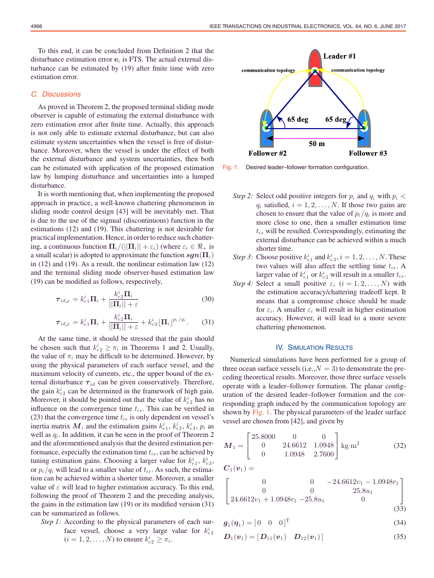
Fig. 1. Desired leader–follower formation configuration.
Step 2: Select odd positive integers for pi and qi with pi <
qi satisfied, i = 1, 2, . . . , N. If those two gains are
chosen to ensure that the value of pi/qi is more and
more close to one, then a smaller estimation time
tis will be resulted. Correspondingly, estimating the
external disturbance can be achieved within a much
shorter time.
e1 or ki
e1 and ki
Step 3: Choose positive ki
e3, i = 1, 2, . . . , N. These
two values will also affect the settling time tis. A
larger value of ki
e3 will result in a smaller tis.
Step 4: Select a small positive εi (i = 1, 2, . . . , N) with
the estimation accuracy/chattering tradeoff kept. It
means that a compromise choice should be made
for εi. A smaller εi will result in higher estimation
accuracy. However, it will lead to a more severe
chattering phenomenon.
IV. SIMULATION RESULTS
Numerical simulations have been performed for a group of
three ocean surface vessels (i.e.,N = 3) to demonstrate the pre-
ceding theoretical results. Moreover, those three surface vessels
operate with a leader–follower formation. The planar config-
uration of the desired leader–follower formation and the cor-
responding graph induced by the communication topology are
shown by Fig. 1. The physical parameters of the leader surface
vessel are chosen from [42], and given by
⎤
⎦ kg·m2
⎡
⎣ 25.8000
(32)
M 1 =
0
0
24.6612
1.0948
1.0948
2.7600
0
0
0
0
C1(v1) =
⎡
⎣
0
0
−24.6612υ1 − 1.0948r1
25.8u1
0
⎤
⎦
24.6612υ1 + 1.0948r1 −25.8u1
g1(η1) = [ 0
D1(v1) = [ D11(v1) D12(v1) ]
0
0 ]T
(33)
(34)
(35)
�
XIAO et al.: NOVEL DISTURBANCE ESTIMATION SCHEME FOR FORMATION CONTROL OF OCEAN SURFACE VESSELS
4999
where
D11(v1) =
and
⎡
⎣ 0.7225 + 1.3274|u1| + 5.8664u1
0
0
⎤
⎦
2
0
D12 (v1 ) =
⎤
⎡
⎥⎦.
⎢⎣
0.8612 + 36.2823|υ1| + 8.05|r1| 0.845|υ1| + 3.45|r1| − 0.1079
−0.1052 − 5.0437|υ1| − 0.13|r1|
The physical parameters of the follower #2 and the follower #3
surface vessels are given by M 2 = M 3, g2(η2) = g3(η3) =
[ 0 0 0 ]T , C2(v2), C3(v3), D2(v2), and D3(v3) which are
determined as follows:
1.9 − 0.08|υ1| + 0.75|r1|
0
M 2 =
C2(v2) =
C3(v3) =
⎤
⎦
0
0
0
22
0
0
0
2.5
⎡
⎣ 15
0
0
⎡
⎣ 0
0
22υ2 −15u2
⎡
0
⎣ 0
0
0
22υ3 −15u3
⎡
⎣ 25
0
0
(36)
(37)
(38)
(39)
⎤
⎦
⎤
⎦
⎤
⎦ .
−22υ2
15u2
−22υ3
15u3
0
0
0
25
0
0
0
15
D2(v2) = D3(v3) =
In the simulation, the initial value of the leader and the fol-
lowers surface vessels are such that
ηi(0) = [ 75 m 50 + 25 sin(65◦)m 60◦ ]T
η2(0) = [ 50 m 50 m 30◦ ]T
η3(0) = [ 100 m 50 m 60◦ ]T
vi(0) = [ 0 m/s
/s ]T , i = 1, 2, 3.
0 m/s
0◦
(40)
(41)
(42)
(43)
The controller for the formation control of these three surface
vessels is the standard PID control. Using there physical param-
eters, controller, and the initial values, the following constant
and time-varying external disturbance scenarios are simulated.
1) The leader surface vessel is under the effect of a time-
varying external disturbance, which is the same as [36]
and given by
⎤
⎥⎦ .
−0.9 + 2 sin(0.02t − π/6) + 1.5 sin(0.3t)
1.3 + 2 sin(0.02t) + 1.5 sin(0.1t)
⎡
⎢⎣
τ 1d =
− sin(0.09t + π/3) − 4 sin(0.01t)
Their units are N, N, and N·m, respectively.
1) The other two surface vessels are under the effect of
(44)
constant external disturbance, i.e.,
τ 2d = τ 3d = [ 1.5 N −1.5 N 0.5 N · m ]T .
(45)
Their units are N, N, and N˙cm, respectively.
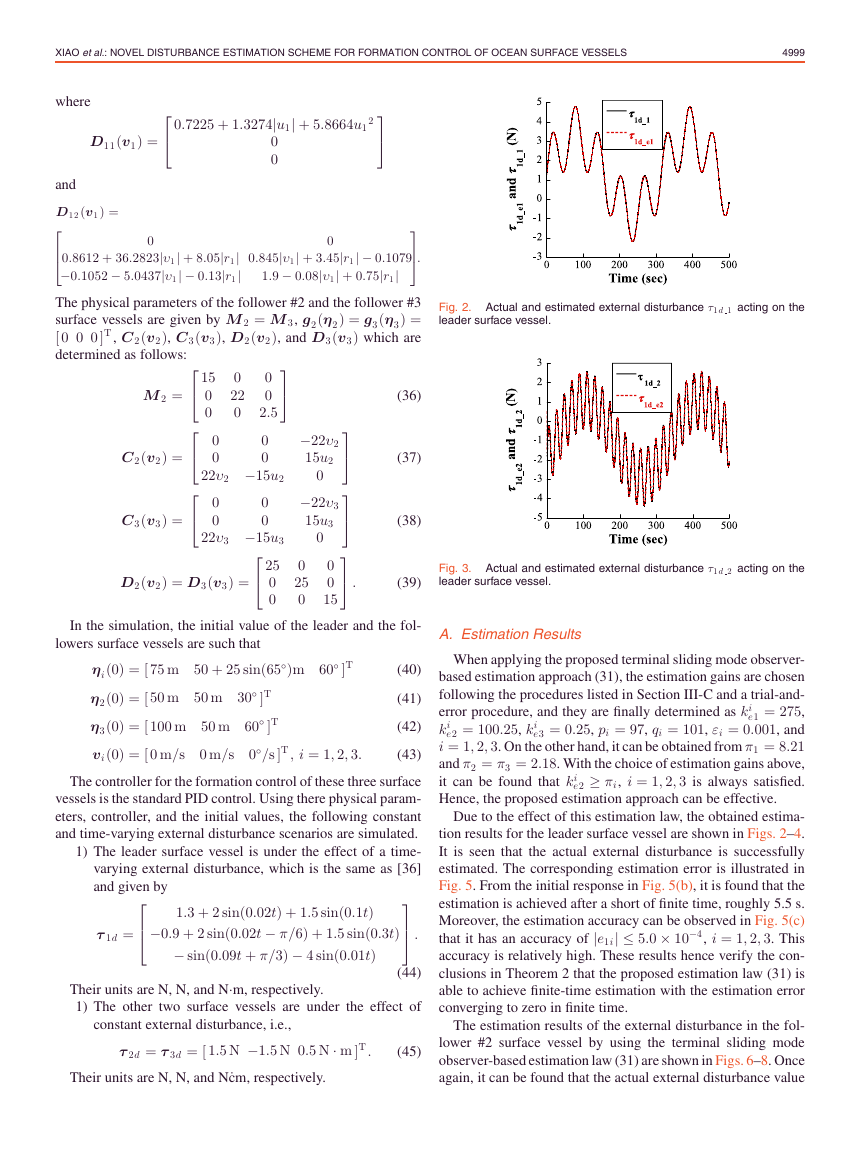
Fig. 2. Actual and estimated external disturbance τ1 d 1 acting on the
leader surface vessel.
Fig. 3. Actual and estimated external disturbance τ1 d 2 acting on the
leader surface vessel.
A. Estimation Results
When applying the proposed terminal sliding mode observer-
based estimation approach (31), the estimation gains are chosen
following the procedures listed in Section III-C and a trial-and-
e1 = 275,
error procedure, and they are finally determined as ki
e3 = 0.25, pi = 97, qi = 101, εi = 0.001, and
e2 = 100.25, ki
ki
i = 1, 2, 3. On the other hand, it can be obtained from π1 = 8.21
and π2 = π3 = 2.18. With the choice of estimation gains above,
e2 ≥ πi, i = 1, 2, 3 is always satisfied.
it can be found that ki
Hence, the proposed estimation approach can be effective.
Due to the effect of this estimation law, the obtained estima-
tion results for the leader surface vessel are shown in Figs. 2–4.
It is seen that the actual external disturbance is successfully
estimated. The corresponding estimation error is illustrated in
Fig. 5. From the initial response in Fig. 5(b), it is found that the
estimation is achieved after a short of finite time, roughly 5.5 s.
Moreover, the estimation accuracy can be observed in Fig. 5(c)
that it has an accuracy of |e1i| ≤ 5.0 × 10⁻⁴, i = 1, 2, 3. This
accuracy is relatively high. These results hence verify the con-
clusions in Theorem 2 that the proposed estimation law (31) is
able to achieve finite-time estimation with the estimation error
converging to zero in finite time.
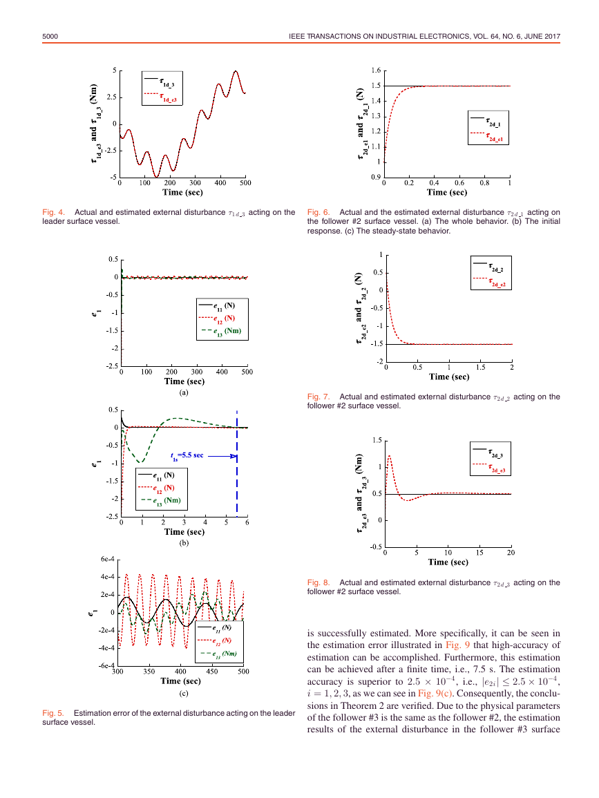
The estimation results of the external disturbance in the fol-
lower #2 surface vessel by using the terminal sliding mode
observer-based estimation law (31) are shown in Figs. 6–8. Once
again, it can be found that the actual external disturbance value
�
5000
IEEE TRANSACTIONS ON INDUSTRIAL ELECTRONICS, VOL. 64, NO. 6, JUNE 2017
Fig. 4. Actual and estimated external disturbance τ1 d 3 acting on the
leader surface vessel.
Fig. 6. Actual and the estimated external disturbance τ2 d 1 acting on
the follower #2 surface vessel. (a) The whole behavior. (b) The initial
response. (c) The steady-state behavior.
Fig. 7. Actual and estimated external disturbance τ2 d 2 acting on the
follower #2 surface vessel.
Fig. 8. Actual and estimated external disturbance τ2 d 3 acting on the
follower #2 surface vessel.
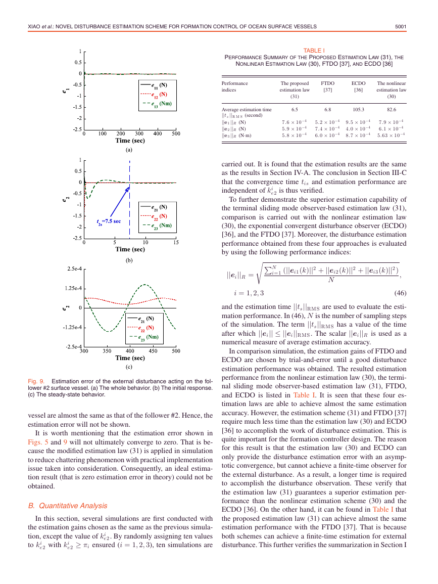
is successfully estimated. More specifically, it can be seen in
the estimation error illustrated in Fig. 9 that high-accuracy of
estimation can be accomplished. Furthermore, this estimation
can be achieved after a finite time, i.e., 7.5 s. The estimation
accuracy is superior to 2.5 × 10⁻⁴, i.e., |e2i| ≤ 2.5 × 10⁻⁴,
i = 1, 2, 3, as we can see in Fig. 9(c). Consequently, the conclu-
sions in Theorem 2 are verified. Due to the physical parameters
of the follower #3 is the same as the follower #2, the estimation
results of the external disturbance in the follower #3 surface
Fig. 5. Estimation error of the external disturbance acting on the leader
surface vessel.
�
XIAO et al.: NOVEL DISTURBANCE ESTIMATION SCHEME FOR FORMATION CONTROL OF OCEAN SURFACE VESSELS
5001
PERFORMANCE SUMMARY OF THE PROPOSED ESTIMATION LAW (31), THE
NONLINEAR ESTIMATION LAW (30), FTDO [37], AND ECDO [36]
TABLE I
Performance
indices
The proposed
estimation law
FTDO
[37]
ECDO
[36]
The nonlinear
estimation law
Average estimation time
||ts ||R M S (second)
||e1 ||R (N)
||e2 ||R (N)
||e3 ||R (N·m)
(31)
6.5
6.8
105.3
(30)
82.6
7.6 × 10⁻⁴
5.9 × 10⁻⁴
5.8 × 10⁻⁴
5.2 × 10⁻⁴
7.4 × 10⁻⁴
6.0 × 10⁻⁴
9.5 × 10⁻⁴
4.0 × 10⁻⁴
8.7 × 10⁻⁴
7.9 × 10⁻⁴
6.1 × 10⁻⁴
5.63 × 10⁻⁴
carried out. It is found that the estimation results are the same
as the results in Section IV-A. The conclusion in Section III-C
that the convergence time tis and estimation performance are
independent of ki
e2 is thus verified.
To further demonstrate the superior estimation capability of
the terminal sliding mode observer-based estimation law (31),
comparison is carried out with the nonlinear estimation law
(30), the exponential convergent disturbance observer (ECDO)
[36], and the FTDO [37]. Moreover, the disturbance estimation
performance obtained from these four approaches is evaluated
by using the following performance indices:
||ei||R =
N
i=1 (||ei1(k)||2 + ||ei2(k)||2 + ||ei3(k)||2)
,
N
i = 1, 2, 3
(46)
and the estimation time ||ts||RMS are used to evaluate the esti-
mation performance. In (46), N is the number of sampling steps
of the simulation. The term ||ts||RMS has a value of the time
after which ||ei|| ≤ ||ei||RMS. The scalar ||ei||R is used as a
numerical measure of average estimation accuracy.
In comparison simulation, the estimation gains of FTDO and
ECDO are chosen by trial-and-error until a good disturbance
estimation performance was obtained. The resulted estimation
performance from the nonlinear estimation law (30), the termi-
nal sliding mode observer-based estimation law (31), FTDO,
and ECDO is listed in Table I. It is seen that these four es-
timation laws are able to achieve almost the same estimation
accuracy. However, the estimation scheme (31) and FTDO [37]
require much less time than the estimation law (30) and ECDO
[36] to accomplish the work of disturbance estimation. This is
quite important for the formation controller design. The reason
for this result is that the estimation law (30) and ECDO can
only provide the disturbance estimation error with an asymp-
totic convergence, but cannot achieve a finite-time observer for
the external disturbance. As a result, a longer time is required
to accomplish the disturbance observation. These verify that
the estimation law (31) guarantees a superior estimation per-
formance than the nonlinear estimation scheme (30) and the
ECDO [36]. On the other hand, it can be found in Table I that
the proposed estimation law (31) can achieve almost the same
estimation performance with the FTDO [37]. That is because
both schemes can achieve a finite-time estimation for external
disturbance. This further verifies the summarization in Section I
Fig. 9. Estimation error of the external disturbance acting on the fol-
lower #2 surface vessel. (a) The whole behavior. (b) The initial response.
(c) The steady-state behavior.
vessel are almost the same as that of the follower #2. Hence, the
estimation error will not be shown.
It is worth mentioning that the estimation error shown in
Figs. 5 and 9 will not ultimately converge to zero. That is be-
cause the modified estimation law (31) is applied in simulation
to reduce chattering phenomenon with practical implementation
issue taken into consideration. Consequently, an ideal estima-
tion result (that is zero estimation error in theory) could not be
obtained.
B. Quantitative Analysis
In this section, several simulations are first conducted with
the estimation gains chosen as the same as the previous simula-
tion, except the value of ki
e2. By randomly assigning ten values
e2 ≥ πi ensured (i = 1, 2, 3), ten simulations are
to ki
e2 with ki
�


 2023年江西萍乡中考道德与法治真题及答案.doc
 2012年重庆南川中考生物真题及答案.doc
 2013年江西师范大学地理学综合及文艺理论基础考研真题.doc
 2020年四川甘孜小升初语文真题及答案I卷.doc
 2020年注册岩土工程师专业基础考试真题及答案.doc
 2023-2024学年福建省厦门市九年级上学期数学月考试题及答案.doc
 2021-2022学年辽宁省沈阳市大东区九年级上学期语文期末试题及答案.doc
 2022-2023学年北京东城区初三第一学期物理期末试卷及答案.doc
 2018上半年江西教师资格初中地理学科知识与教学能力真题及答案.doc
 2012年河北国家公务员申论考试真题及答案-省级.doc
 2020-2021学年江苏省扬州市江都区邵樊片九年级上学期数学第一次质量检测试题及答案.doc
 2022下半年黑龙江教师资格证中学综合素质真题及答案.doc