G LOBALNAV
INSTALLATION AND OPERATION
MANUAL
PDF compression, OCR, web-optimization with CVISION's PdfCompressor
988-0129-01
LITHO IN U.S.A.
I®LOWRANCE ELECTRONICS, INC.
12000 F. SKELLY DR, TULSA, OK 74128
�
NOTES:
Copyright © 1991, Lowrance Electronics, Inc.
All rights reserved.
WARNING!
USE THIS GPS RECEIVER ONLY AS AN AID TO NAVIGA-
TION. A CAREFUL NAVIGATOR NEVER RELYS ON ONLY
ONE METHOD TO OBTAIN POSITION INFORMATION.
CAUTION
This GPS receiver, (like all GE'S navigation equipment) will show
the shortest, most direct path to a waypoint. It provides naviga-
tion data to the waypoint regardless of obstructions. Therefore,
the pnident navigator will not only take advantage of all available
navigation tools when travelling to a waypoint, but will also visu-
ally check to make certain a clear, sate path to the waypoint is
always available.
NOTICE!
As of this writing, the Department of Defense (DOD) has not
declared the GPS navigation system as operational. The system
is still in a testing phase. Satellites can be turned off or accuracy
can be degraded at will by the system operators. Remember
that the GlobalNav, or any GPS receiver is only as accurate as
the system it's using.
Features and specifications subject to change without notice.
All display screens in this manual are simulated.
PDF compression, OCR, web-optimization with CVISION's PdfCompressor
�
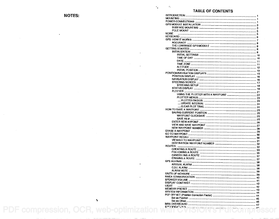
INTRODUCTION . 1
MOUNTING
POWER CONNECTIONS
GPS MODULE INSTALLATION
NOISE
KEYDOARD
GE'S -HOW IT WORKS
ACCURACY
THE LOWRANCE GPS MODULE
TABLE OF CONTENTS
SURFACE MOUNTING
POLE MOUNT
GETTING STARTED
INITIALIZATION
INITIAL SETTINGS
TIME OF DAY
DATE
TIMEZONE
ALTITUDE
INITIAL POSITION
POSITION/NAVIGATION DISPLAYS
POSITION DISPLAY
NAVIGATION DISPLAY
STEERING SCREEN
STEERING SETUP
STATUS DISPLAY
PLOTTER
USING THE PLOTTER WITH A WAYPOINT
PLOTTER MENUS
MOTES.
3
3
5
s
6
7
8
9
9
9
Ic
ii
11
12
13
Is
16
16
17
Is
19
21
22
23
23
24
24
25
25
25
25
26
27
26
29
ao
31
32
32
33
35
37
37
38
38
39
40
41
42
42
44
44
45
46
47
48
PLOTtER RADIUS
UPDATE INTERVAL
....CLEARPLOTTRAIL
HOW TO SAVE A WAYPOINT
SAVING CURRENT POSITION
WAYPOINT QUICKSAVE
SAVEAS#
ENTER NEW AYPOINT
VIEW AND SAVE WAYPOINT
NEW WAYPOINT NUMBER
ERASE A WAYPOINT
GOTOWAYPOINT
WAYPOINT RECALL
VIEW/GO TO WAYPOINT
DESTINATION WAYPOINT NUMBER
ROUTES
CREATING A ROUTE
FOLLOWING A ROUTE
CANCELLING A ROUTE
ERASING A ROUTE
GPSALARMS
ARRIVAL ALARM
CDI. ALARM
ALARM MUTE
UNITS OF MEASURE
NMEA COMMUNICATION
SPEAKERVOLIJME
DISPLAY CONTRAST
LIGHT
MEMORY-PRESET
SYSTEM INFORMATION
PCF OFFSET (PosItIon CorrectIon Factor)
SoI as PosItIon
Set as Onset
MAN OVERBOARD
SPECIFICATIONS
PDF compression, OCR, web-optimization with CVISION's PdfCompressor
�
NOTES:
NOTES:
PDF compression, OCR, web-optimization with CVISION's PdfCompressor
�
NOTES:
INTRODUCTION
The GlobalNav represents one of the best values in GPS receiv-
ers today. It rivals other GPS units costing much more in both
features and performance. The GlobalNav offers easy-to-use
operation at the touch of a button.
Although the GlobalNav has many features and functions, the
"soft key" menu system makes it easy to use. Above all, don't be
afraid to try different features and functions on the unit. You
can't hurt it by pressing buttons!
Read this manual and take ft with you the first few times you use
It makes a great reference should you need it. The
your unit.
more you know when you get to the water, the more your
GlobalNav can do for you!
MOUNTING
Install the GlobalNav in any convenient location, provided there is
clearance behind the unit when it is tilted for the best viewing
angle. Holes in the bracket base allow wood screw or through-
bolt mounting. You may need to place a piece of plywood on the
back of thin fiberglass panels to secure the mounting hardware.
Make certain there is enough room behind the unit to attach the
power and GPS cables.
The smallest hole that will pass the GPS module's connector is
91 16". After drilling the hole, pass the GPS connector up
through the hole first, then pass the power cable down through it.
After the cables have been routed, fill the hole with a good
marine sealing compound. Offset the bracket to cover the hole.
POWER CONNECTIONS
The GlobalNav works from a twelve-volt battery system only.
You can attach the power cable to an accessory or power buss,
however if you have problems with electrical interference, then
attach the power cable directly to the battery. If the cable is not
long enough, splice #18 gauge wire onto it.
PDF compression, OCR, web-optimization with CVISION's PdfCompressor
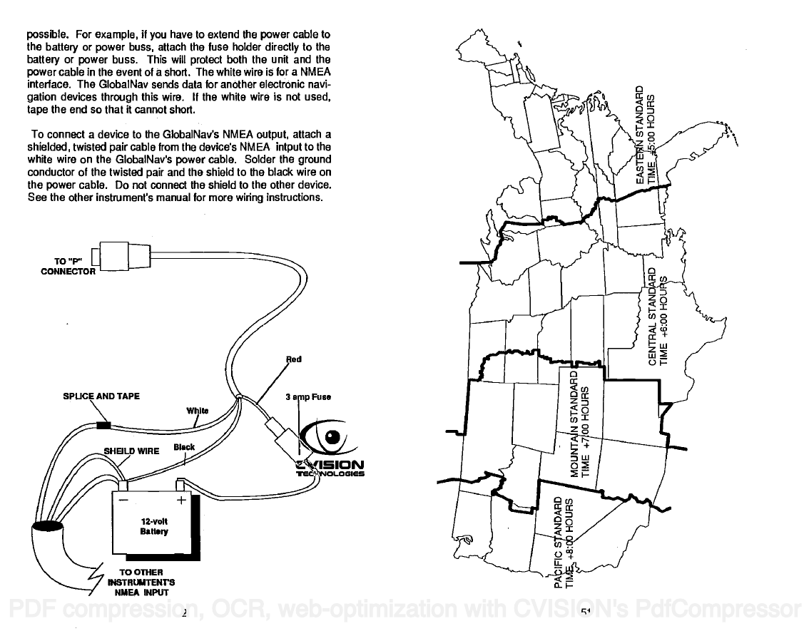
The power cable has three wires; red, white, and black. Red is
the posilive lead, black is negative or ground. Attach the in-line
fuse holder to the red lead as close to the power source as
I
�
possible. For example, if you have to extend the power cable to
the battery or power buss, attach the fuse holder directly to the
battery or power buss. This will protect both the unit and the
power cable in the event of a short. The white wire is for a NMEA
interface. The GlobalNav sends data for another electronic navi-
gation devices through this wire. If the white wire is not used,
tape the end so that it cannot short.
To connect a device to the GlobalNav's NMEA output, attach a
shielded, twisted pair cable from the device's NMEA intput to the
white wire on the GlobalNav's power cable. Solder the ground
conductor of the twisted pair and the shield to the black wire on
the power cable. Do not connect the shield to the other device.
See the other instrument's manual for more wiring instructions.
TO 'P'
CONNECTOR
AND TAPE
rd
Fuse
To OThER
IPISTHUMTENVS
NMEA INPUT
PDF compression, OCR, web-optimization with CVISION's PdfCompressor
ci
2
�
See the NMEA section in this manual for more information. The
GlobalNav automatically sends NMEA data out the while wire
once it acquires and 'locks on" to the satellites.
GPS MODULE INSTALLATION
The GPS module can be installed on a flat surface or (with the
supplied adapter) on a pole. Mount the module in an area that
guarantees a clear view of the sky at all times. In order for the
module to receive the signals from the satellites, it must not be
obstructed. An ideal location is on a cabin roof, or deck. The
gunnels also make a good location. Attaching the pole mounting
adapter lets you install the module on a one inch mast. A high
location is preferred. However, for lightning protection, the an-
tenna shouln'l be the highest part of the boat.
Surface Mounting - With Access
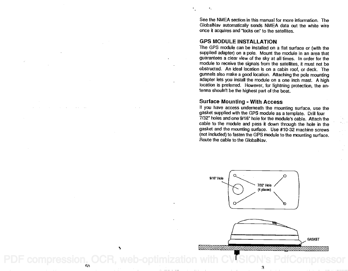
If you have access underneath the mounting surface, use the
gasket supplied with the GPS module as a template. Drill four
7/32" holes and one 9/16" hole for the module's cable. Attach the
cable to the module and pass it down through the hole in the
gasket and the mounting surface. Use #10-32 machine screws
(not included) to fasten the GPS module to the mounting surface.
Route the cable to the GlobalNav.
9/16' 1-lob
PDF compression, OCR, web-optimization with CVISION's PdfCompressor
çç
/////////a ////////////
_______________________-
JGA5KET
�
GLOBALNAV PS RECEIVER SPECIFICATIONS
GPS Module Dimensions ..2.5"H x 4.1"W x 7" D
Channels
Five Parallel
Four continuous for position
All satellites in view tracked
One second
Maximum accuracy achievable
with Standard Positioning Service
Position: 25 meters CEP
Velocity: 0.25 meters/sec RMS
Without SA PDOP.c6.0
Update rate
Accuracy
NMEA 0183 SENTENCES
RMB
RMC
GLL
APA
DBK
MTW
VHW
VLW
Minimum Recommended Sentence,
Part B
Minimum Recommended Sentence,
Part C
Present Position - Latitude/Longitude
Autopilot Steering Data
Water Depth
Water Temperature (°C)
Speed Through Water (KPH)
Distance Travelled/LOG (NM)
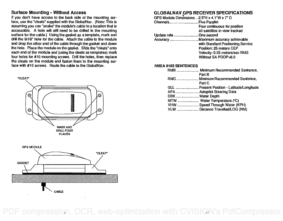
Surface Mounting - Without Access
If you don't have access to the back side of the mounting sur-
face1 use the "cleats" supplied with the GlobalNav. (Note: This is
assuming you can "snake" the module's cable to a location that is
accessable. A hole will still need to be drilled in the mounting
surface for the cable.) Using the gasket as a template, mark and
drill the 9/16" hole for the cable. Attach the cable to the module
and drop the other end of the cable through the gasket and down
the hole. Place the module on the gasket. Slide the "cleats" onto
each end of the module and (using the cleats as templates) mark
four holes for #10 mounting screws. Drill the holes, then replace
the cleats on the module and fasten them to the mounting sur-
face with #10 screws. Route the cable to the GlobalNav.
tLEAV
OPS MODULE
GASKET
MARK AND
DRILL FOUR
PLAcEs
CABLE
CLEAV
PDF compression, OCR, web-optimization with CVISION's PdfCompressor
An
4
�



 2023年江西萍乡中考道德与法治真题及答案.doc
 2012年重庆南川中考生物真题及答案.doc
 2013年江西师范大学地理学综合及文艺理论基础考研真题.doc
 2020年四川甘孜小升初语文真题及答案I卷.doc
 2020年注册岩土工程师专业基础考试真题及答案.doc
 2023-2024学年福建省厦门市九年级上学期数学月考试题及答案.doc
 2021-2022学年辽宁省沈阳市大东区九年级上学期语文期末试题及答案.doc
 2022-2023学年北京东城区初三第一学期物理期末试卷及答案.doc
 2018上半年江西教师资格初中地理学科知识与教学能力真题及答案.doc
 2012年河北国家公务员申论考试真题及答案-省级.doc
 2020-2021学年江苏省扬州市江都区邵樊片九年级上学期数学第一次质量检测试题及答案.doc
 2022下半年黑龙江教师资格证中学综合素质真题及答案.doc