DIRECT DRIVE
ANALOG CONTROL
SERVO VALVES
D633 SIZE 03
D634 SIZE 05
HIGH PRODUCTIVITY FOR DEMANDING APPLICATIONS
THAT REQUIRE A HIGHLY DYNAMIC RESPONSE AND
FLEXIBLE INTEGRATION.
WHAT MOVES YOUR WORLD
Rev. C, April 2020�
INTRODUCTION
Direct Drive Analog Control Servo Valves
Whenever the highest levels of motion control performance
and design flexibility are required, you’ll find Moog expertise
at work. Through collaboration, creativity and world-class
technological solutions, we help you overcome your tough-
est engineering obstacles. Enhance your machine’s perfor-
mance, and help take your thinking further than you ever
thought possible.
INTRODUCTION .............................................................................. 2
Product Overview ..................................................................... 3
Description of Operation ....................................................... 5
Features and Benefits ............................................................ 6
TECHNICAL DATA .......................................................................... 7
Size 03 - D633 Servo Valve .................................................. 7
Size 05 - D634 Servo Valve ................................................12
BACKGROUND ..............................................................................17
Electronics ................................................................................17
Flow Calculation .....................................................................19
ORDERING INFORMATION .......................................................20
Accessories and Spare Parts .............................................20
Moog Global Support ............................................................24
Ordering Code..........................................................................25
This catalog is for users with technical knowledge. To ensure all necessary characteristics for function and safety of the system, the user has
to check the suitability of the products described herein. The products described herein are subject to change without notice. In case of doubt,
please contact Moog.
Moog is a registered trademark of Moog Inc. and its subsidiaries.
All trademarks as indicated herein are the property of Moog Inc. and its subsidiaries.
For the full disclaimer refer to www.moog.com/literature/disclaimers.
For the most current information, visit www.moog.com/industrial or contact your local Moog office.
2
Rev. C, April 2020 �
INTRODUCTION
Direct Drive Analog Control Servo Valves
PRODUCT OVERVIEW
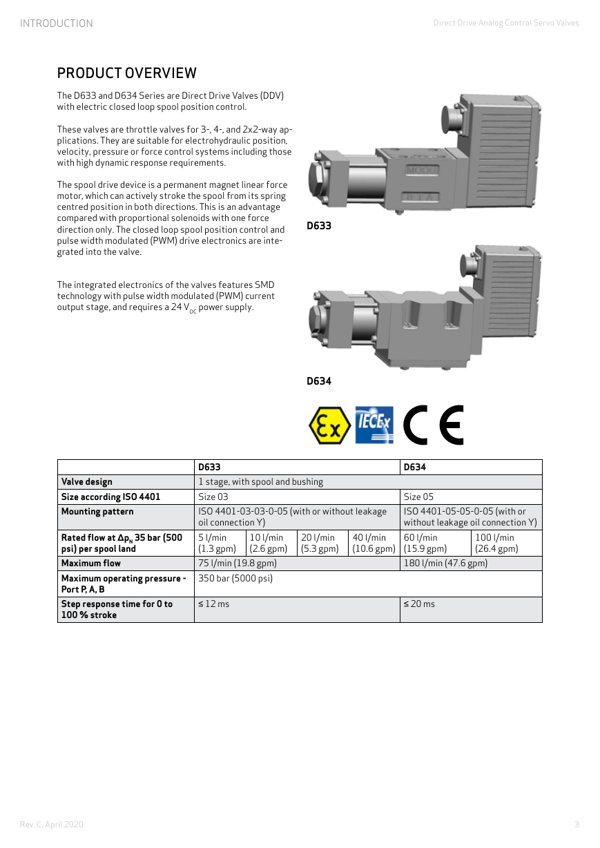
The D633 and D634 Series are Direct Drive Valves (DDV)
with electric closed loop spool position control.
These valves are throttle valves for 3-, 4-, and 2x2-way ap-
plications. They are suitable for electrohydraulic position,
velocity, pressure or force control systems including those
with high dynamic response requirements.
The spool drive device is a permanent magnet linear force
motor, which can actively stroke the spool from its spring
centred position in both directions. This is an advantage
compared with proportional solenoids with one force
direction only. The closed loop spool position control and
pulse width modulated (PWM) drive electronics are inte-
grated into the valve.
The integrated electronics of the valves features SMD
technology with pulse width modulated (PWM) current
output stage, and requires a 24 VDC power supply.
D633
D634
Valve design
Size according ISO 4401
Mounting pattern
Rated flow at ΔpN 35 bar (500
psi) per spool land
Maximum flow
Maximum operating pressure -
Port P, A, B
Step response time for 0 to
100 % stroke
D633
1 stage, with spool and bushing
Size 03
ISO 4401-03-03-0-05 (with or without leakage
oil connection Y)
5 l/min
(1.3 gpm)
75 l/min (19.8 gpm)
350 bar (5000 psi)
10 l/min
(2.6 gpm)
20 l/min
(5.3 gpm)
40 l/min
(10.6 gpm)
D634
Size 05
ISO 4401-05-05-0-05 (with or
without leakage oil connection Y)
60 l/min
(15.9 gpm)
180 l/min (47.6 gpm)
100 l/min
(26.4 gpm)
≤ 12 ms
≤ 20 ms
3
Rev. C, April 2020 �
INTRODUCTION
Direct Drive Analog Control Servo Valves
Explosion Protection
Valves D633K and D634K available with explosion
protection for Gas:
• Ex II 2G Ex db eb IIB+H2 T* Gb
according to EN 60079-0, EN 60079-1 and EN 60079-7.
• Ex db eb IIB+H2 T* Gb
according to IEC 60079-0, IEC 60079-1, IEC 60079-7.
Valves D633D available with explosion protection for
Dust:
• Ex II 2D Ex tb IIIC T155°C Db
• Ex II 3D Ex tc IIIC T155°C Dc
according to EN 60079-31, EN 600079-0.
Note: Installation dimensions and electric connection
altered.
PRODUCT OVERVIEW
Design and Application
A permanent magnet linear force motor is used to drive
the spool. In contrast to proportional solenoid drives, the
linear force motor drives the spool in both working direc-
tions from the spring-centered middle position. The strong
actuating force of the spool, provides Moog Servo Valves
with excellent static and dynamic characteristics.
Spool Position Control
In this operating mode of the servo valve, the spool
position is controlled. The command signal is proportional
to a desired spool position. A position transducer (LVDT)
measures the spool‘s actual position, and forwards this
information to the valve electronics. The system electron-
ics compare the actual spool position with the command
signal. This generates a signal that drives the linear force
motor and brings the spool to the correct position.
Optional Valve Features
Moog offers a range of optional features. These include
options to ruggedize valves for operation in extremely
demanding environments, and valves designed for special
applications and fluids. The following sections provide
short overviews of these functions. Please contact Moog
for more detailed information.
Valves for Operation with Ester Based Fluids
Standard hydraulic seal materials such as HNBR and FKM,
are frequently incompatible with fire resistant phosphate
ester based fluids. In order to use valves with this type of
fluid, Moog offers them as special seal versions that are
mineral oil and phosphate ester resistant. Please note:
These valve types are tested by Moog using mineral oil,
remnants of which will remain in the valve after testing.
4
Rev. C, April 2020 �
INTRODUCTION
Direct Drive Analog Control Servo Valves
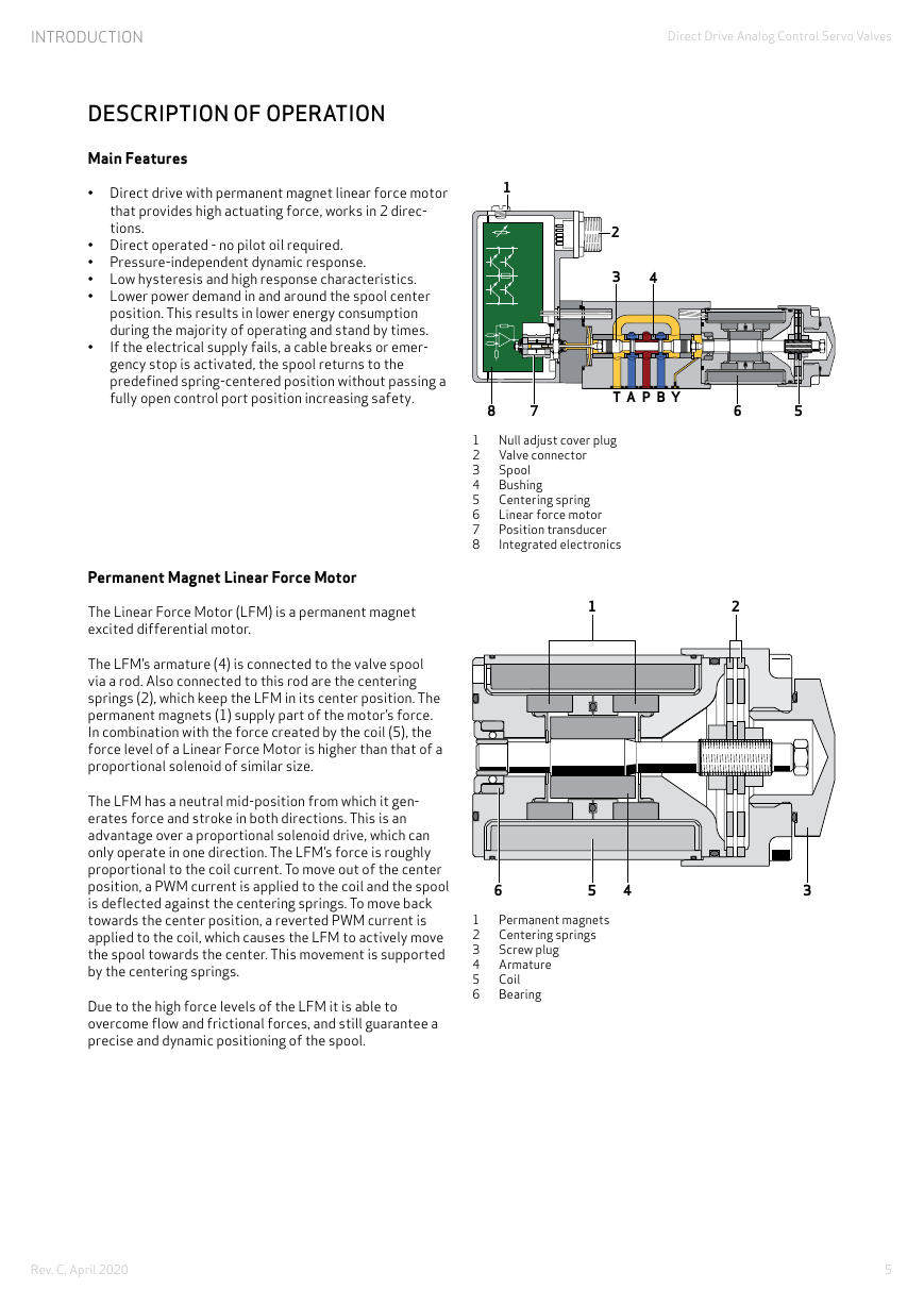
DESCRIPTION OF OPERATION
Main Features
• Direct drive with permanent magnet linear force motor
that provides high actuating force, works in 2 direc-
tions.
• Direct operated - no pilot oil required.
• Pressure-independent dynamic response.
• Low hysteresis and high response characteristics.
• Lower power demand in and around the spool center
•
position. This results in lower energy consumption
during the majority of operating and stand by times.
If the electrical supply fails, a cable breaks or emer-
gency stop is activated, the spool returns to the
predefined spring-centered position without passing a
fully open control port position increasing safety.
Permanent Magnet Linear Force Motor
The Linear Force Motor (LFM) is a permanent magnet
excited differential motor.
The LFM’s armature (4) is connected to the valve spool
via a rod. Also connected to this rod are the centering
springs (2), which keep the LFM in its center position. The
permanent magnets (1) supply part of the motor’s force.
In combination with the force created by the coil (5), the
force level of a Linear Force Motor is higher than that of a
proportional solenoid of similar size.
The LFM has a neutral mid-position from which it gen-
erates force and stroke in both directions. This is an
advantage over a proportional solenoid drive, which can
only operate in one direction. The LFM’s force is roughly
proportional to the coil current. To move out of the center
position, a PWM current is applied to the coil and the spool
is deflected against the centering springs. To move back
towards the center position, a reverted PWM current is
applied to the coil, which causes the LFM to actively move
the spool towards the center. This movement is supported
by the centering springs.
Due to the high force levels of the LFM it is able to
overcome flow and frictional forces, and still guarantee a
precise and dynamic positioning of the spool.
1
2
3
4
8
7
T A
P
YB
6
5
1 Null adjust cover plug
2 Valve connector
3
4
5
6
7
8
Spool
Bushing
Centering spring
Linear force motor
Position transducer
Integrated electronics
1
2
6
5
4
3
Permanent magnets
1
Centering springs
2
3
Screw plug
4 Armature
5
6
Coil
Bearing
5
Rev. C, April 2020 �
INTRODUCTION
Direct Drive Analog Control Servo Valves
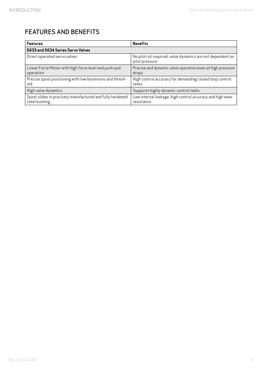
FEATURES AND BENEFITS
Features
D633 and D634 Series Servo Valves
Direct operated servo valves
Linear Force Motor with high force level and push-pull
operation
Precise spool positioning with low hysteresis and thresh-
old
High valve dynamics
Spool slides in precisely manufactured and fully hardened
steel bushing
Benefits
No pilot oil required, valve dynamics are not dependent on
pilot pressure
Precise and dynamic valve operation even at high pressure
drops
High control accuracy for demanding closed loop control
tasks
Supports highly dynamic control tasks
Low internal leakage, high control accuracy and high wear
resistance
6
Rev. C, April 2020 �
TECHNICAL DATA
Direct Drive Analog Control Servo Valves
1 stage, with spool and bushing
ISO 4401-03-03-0-05
(with or without leakage oil connection Y)
Any
2.5 kg (5.51 lb)
-40 - +80 °C (-40 - +176 °F)
-20 - +60 °C (-4 - +140 °F)
30 g, 3 axis, 10 Hz to 2 kHz
50 g, 6 directions, 3 ms
150 years
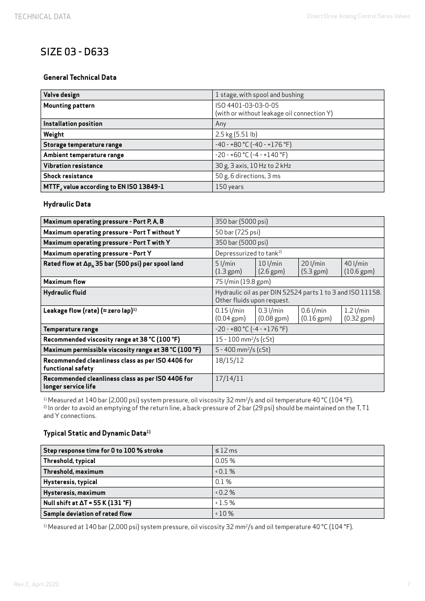
SIZE 03 - D633
General Technical Data
Valve design
Mounting pattern
Installation position
Weight
Storage temperature range
Ambient temperature range
Vibration resistance
Shock resistance
MTTFd value according to EN ISO 13849-1
Hydraulic Data
Maximum operating pressure - Port P, A, B
Maximum operating pressure - Port T without Y
Maximum operating pressure - Port T with Y
Maximum operating pressure - Port Y
Rated flow at ΔpN 35 bar (500 psi) per spool land
Maximum flow
Hydraulic fluid
Leakage flow (rate) (≈ zero lap)1)
20 l/min
(5.3 gpm)
40 l/min
(10.6 gpm)
350 bar (5000 psi)
50 bar (725 psi)
350 bar (5000 psi)
Depressurized to tank2)
10 l/min
5 l/min
(1.3 gpm)
(2.6 gpm)
75 l/min (19.8 gpm)
Hydraulic oil as per DIN 52524 parts 1 to 3 and ISO 11158.
Other fluids upon request.
0.3 l/min
0.15 l/min
(0.04 gpm)
(0.08 gpm)
-20 - +80 °C (-4 - +176 °F)
15 - 100 mm2/s (cSt)
5 - 400 mm2/s (cSt)
18/15/12
0.6 l/min
(0.16 gpm)
1.2 l/min
(0.32 gpm)
Temperature range
Recommended viscosity range at 38 °C (100 °F)
Maximum permissible viscosity range at 38 °C (100 °F)
Recommended cleanliness class as per ISO 4406 for
functional safety
Recommended cleanliness class as per ISO 4406 for
longer service life
1) Measured at 140 bar (2,000 psi) system pressure, oil viscosity 32 mm2/s and oil temperature 40 °C (104 °F).
2) In order to avoid an emptying of the return line, a back-pressure of 2 bar (29 psi) should be maintained on the T, T1
and Y connections.
17/14/11
Typical Static and Dynamic Data1)
Step response time for 0 to 100 % stroke
Threshold, typical
Threshold, maximum
Hysteresis, typical
Hysteresis, maximum
Null shift at ΔT = 55 K (131 °F)
Sample deviation of rated flow
1) Measured at 140 bar (2,000 psi) system pressure, oil viscosity 32 mm2/s and oil temperature 40 °C (104 °F).
≤ 12 ms
0.05 %
< 0.1 %
0.1 %
< 0.2 %
< 1.5 %
< 10 %
7
Rev. C, April 2020 �
TECHNICAL DATA
Direct Drive Analog Control Servo Valves
SIZE 03 - D633
Electrical Data
Duty cycle
Degree of protection according to IEC/EN 60529
Supply voltage1)
Permissible ripple of supply voltage2)
Maximum current consumption3)
Power consumption of the motor in middle position
Power consumption maximum
Fuse protection, external, per valve
EM compatibility
100 %
IP65 with mounted mating plugs
24 VDC, min. 19 VDC, max. 32 VDC
±3 VRMS
1.2 A
9.6 W (0.4 A @ 24 VDC)
28.8 W (1.2 A @ 24 VDC)
1.6 A (slow)
Immunity to interference as per DIN EN 61000-6-2 (evalu-
ation criterion A)
1) All connected circuits must be isolated from the main supply by „electrical separation” in accordance with IEC/EN
61558-1 and IEC/EN 61558-2-6. Voltages must be limited to the safety extra-low voltage range in accordance with EN
60204-1. We recommend the use of SELV/PELV power packs.
2) Frequency from 50 Hz to 10 kHz.
3) Measured at ambient temperature 25 °C (77 °F) and supply voltage 24 V.
8
Rev. C, April 2020 �


 2023年江西萍乡中考道德与法治真题及答案.doc
 2012年重庆南川中考生物真题及答案.doc
 2013年江西师范大学地理学综合及文艺理论基础考研真题.doc
 2020年四川甘孜小升初语文真题及答案I卷.doc
 2020年注册岩土工程师专业基础考试真题及答案.doc
 2023-2024学年福建省厦门市九年级上学期数学月考试题及答案.doc
 2021-2022学年辽宁省沈阳市大东区九年级上学期语文期末试题及答案.doc
 2022-2023学年北京东城区初三第一学期物理期末试卷及答案.doc
 2018上半年江西教师资格初中地理学科知识与教学能力真题及答案.doc
 2012年河北国家公务员申论考试真题及答案-省级.doc
 2020-2021学年江苏省扬州市江都区邵樊片九年级上学期数学第一次质量检测试题及答案.doc
 2022下半年黑龙江教师资格证中学综合素质真题及答案.doc