Image and Vision Computing 23 (2005) 59–67
www.elsevier.com/locate/imavis
Complete calibration of a structured light stripe vision sensor through
planar target of unknown orientations
Fuqiang Zhou*, Guangjun Zhang
School of Instrument Science and Opto-electronics Engineering, Beijing University of Aeronautics and Astronautics, Beijing 100083, China
Received 30 January 2004; accepted 7 July 2004
Abstract
Structured light 3D vision inspection is a commonly used method for various 3D surface profiling techniques. In this paper, the
mathematical model of the structured light stripe vision sensor is established. We propose a flexible new approach to easily determine all
primitive parameters of a structured light stripe vision sensor. It is well suited for use without specialized knowledge of 3D geometry. The
technique only requires the sensor to observe a planar target shown at a few (at least two) different orientations. Either the sensor or the planar
target can be freely moved. The motion need not be known. A novel approach is proposed to generate sufficient non-collinear control points
for structured light stripe vision sensor calibration. Real data has been used to test the proposed technique, and very good result has been
obtained. Compared with classical techniques, which use expensive equipment such as two or three orthogonal planes, the proposed
technique is easy to use and flexible. It advances structured light vision one step from laboratory environments to real engineering 3D
metrology applications.
q 2004 Elsevier B.V. All rights reserved.
Keywords: Structured light; Calibration; Control points; Planar target; Vision inspection
1. Introduction
With the development of electronics, photo-electronics,
image processing and computer vision technique, vision
inspection has made giant strides in development. It is
becoming increasingly relevant in industry for dimensional
analysis, on-line inspection, component quality control and
solid modeling, such as the 3D contouring and gauging of
large-surface car parts and small-size microelectronic
components, and the fast-dimensional analysis of object in
relation to the recognition of targets by robots. And also it
played an important role in reverse engineering.
Recently, systems based on vision cameras allow
automated and non-contact 3D measurements, which are
based on two alternative techniques: stereovision and
triangulation from structured light stripe vision. Structured
light stripe vision inspection avoids the so-called corre-
spondence problem of passive stereo vision and has gained
* Corresponding author. Tel.: C86 10 82316930; fax: C86 10 82314804.
E-mail address: fuqiang_zhou@yahoo.com (F. Zhou).
0262-8856/$ - see front matter q 2004 Elsevier B.V. All rights reserved.
doi:10.1016/j.imavis.2004.07.006
the widest acceptance [1–4] in industry inspections due to
fast measuring speed, very simple optical arrangement, non-
contact, moderate accuracy, low cost, and robust nature in
the presence of ambient light source in situ. Since the early
1970s [5], research has been active on shape reconstruction
and object recognition by projecting structured light stripes
onto objects.
A basic structured light stripe vision sensor consists of
one camera and one laser projector, which together form an
active stereo pair. The projector is displaced relative to the
camera in space. For example, one of arrangements is
shown in Fig. 1, the light stripe is modulated by the depth of
the measured surface. Thus,
the deformed light stripe
contains rich 3D characteristic information of the object
surface. The camera captures the image of the object with
the deformed light stripe. The task of structured light vision
inspection is to acquire the 3D characteristic information of
the measured surface from the 2D deformed light stripe
image,
i.e. 3D reconstruction. A structured light stripe
vision sensor generates dense world points by sampling
image points on each light stripe in the image. The absence
�
60
F. Zhou, G. Zhang / Image and Vision Computing 23 (2005) 59–67
The approaches for estimating the structured light vision
sensor’s model parameters are determined by the estab-
lished mathematical model itself. Currently, there has been
two major ways to establish the mathematical models of
structured light stripe vision sensor. One is based on the
simple triangular methodology, and another is based on the
perspective, translation and rotation transforms in hom-
ogenous coordinate system [4]. The perspective projection
model is broadly used in the 3D vision inspection. Until
now,
the extraction of calibration world points for a
structured light vision sensor has remained a difficult
problem. This is because usually the known world points
on the calibration object do not normally fall on the light
stripe plane illuminated from the projector, which poses
difficulty for the sensor calibration.
Different approaches for calibrating structured light
vision sensor have been proposed in many literatures.
In Refs. [12,13], several
thin threads that are non-
coplanar are strained in the space, and the illuminated light
stripe plane from the projector of the structured light vision
sensor will intersect the threads at several bright light dots,
and these bright light dots are used as the control points.
Then a 3D coordinate measuring system such as movable
theodolite measurement system is used to measure the 3D
coordinates of the bright light dots. However, the strained
thread method has the following disadvantage: (1) another
3D calibration target is needed to calibrate camera; (2) the
procedure to generate control points for projector cali-
bration is too complex, and only a few points are obtained;
(3) as the bright light dot is in fact a kind of distribution of
light intensity, it is difficult to match the world bright light
dots on the thread strictly with the image bright light dots in
the camera image plane, thus the accuracy of the obtained
control points is usually poor.
In the Ref. [14], a more sophisticated calibration target is
used, which has a zigzag-like face. This method uses the
intersection, which are generated by the emitted light stripe
plane intersecting with the ridge of the zigzag, as the control
points. In this method, the light stripe plane is perpendicular
to the datum plane lying on the zigzag is required.
Moreover, it has similar problems as the strained thread
method.
Chen and Kak [15] proposed the method of the known
world line and image point correspondences to directly get
the image-to-world transformation matrix. In this method, at
least six world lines are required. Later Reid [16] extended
the concept to the known world plane and image point
correspondence. In Reid’s method, a number of known
world planes are required.
Xu et al. [17] and Huynh [18] proposed, respectively, a
method that is based on the invariance of the cross-ratio to
generate the world points on the light stripe plane. The
control points can be got by a calibration target whose
geometry in 3D space is known with very good precision.
The 3D calibration target usually consists of two or three
planes orthogonal
to be
to each other and is difficult
Fig. 1. Overview of the structured light vision sensor.
of the difficult matching problem makes active stereo an
attractive method for many vision inspection tasks with
the trade-off that the sensor must be fully calibrated prior to
use [6].
In the camera calibration stage,
The procedures to estimate the sensor model parameters
are referred to sensor calibration. Sensor calibration is
necessary step in vision inspection in order to extract metric
information from 2D images. The traditional approach to
calibrating a structured light stripe sensor incorporates two
separate stages: camera calibration and projector calibration.
the world-to-image
perspective transformation matrix and the distorted coeffi-
cient are estimated using at least six non-coplanar world
points and their corresponding image projection points [7].
The transformation matrix can be decomposed into camera
intrinsic parameters (e.g. effective focal length, principal
point and skew coefficient) and extrinsic parameters
(including the 3D position and orientation of the camera
frame relative to a certain world coordinate system).
Camera calibration is performed by observing a calibration
object whose geometry in 3D space is known with very
good precision. Calibration can be done very efficiently [8,
9]. The calibration target usually consists of two or three
planes orthogonal
to each other. Sometimes, a plane
undergoing a precisely known translation is also used
[10]. These approaches require an expensive calibration
apparatus, and an elaborate set-up. Zhang proposed a
flexible new technique for camera calibration by view a
plane from the different unknown orientations,
this
approach is very easy to use and obtained very good
calibration accuracy [11].
In the projector calibration stage, the coefficients of the
equation of light stripe plane relative to the same 3D
coordination frame must be determined. The projector
calibration is related to two principal procedures. One is
constructing non-collinear control points. The 3D world
coordinates of those control points and their corresponding
2D image coordinates can be estimated in this procedure.
The other is establishing the mathematical model of the
sensor and estimating the parameters of the model.
�
F. Zhou, G. Zhang / Image and Vision Computing 23 (2005) 59–67
61
2. Mathematical model of the structured light stripe
vision sensor
2.1. Camera model
manufactured accurately. It is also very difficult to capture
the good calibration image by simultaneously viewing the
different planes of
the 3D calibration object. These
approaches require an expensive calibration apparatus.
Besides the methods already mentioned, there are other
methods in the literature, such as, standard ruler calibration
target mounted on a step-motor-controlled stage with one
linear translation axis [19–21], a photoelectrical aiming
device combined with a 3D movable platform [22], and so
on. But because all these methods are demanding for the
precision of the moveable stage, inconvenient for operation,
and time-consuming in calibration, none of them is suitable
for or widely accepted on-line calibration.
To sum up, the methods of calibrating a structured light
vision sensor presented in the literature mainly have the
following drawbacks:
(1) it is difficult to generate large number of highly accurate
control points.
(2) some methods require an expensive calibration appar-
atus, and elaborate setup.
(3) the method is well unsuitable for on line sensor
calibration in situ.
These factors obstruct the improvement of the calibration
accuracy of structured light vision sensor and their
engineering 3D metrology applications.
In this paper, inspired by the work of Huynh and the work
of Zhang, we propose a novel approach that employs the
invariance of a cross-ratio to generate an arbitrary number of
control points on the light stripe plane by viewing a plane
from unknown orientations. The captured images of the
planar target can be used for camera calibration and projector
calibration simultaneously. The proposed techniques only
requires the camera to observe a planar target shown at a few
(at least two) different orientations. The target can be printed
on a laser printer and attached to a ‘reasonable’ planar surface
(e.g. a hard book cover). The planar target can be moved by
hand. The motion need not be known. In many respects the
approach taken here is similar to bundle adjustment
procedures used in photogrammetry in that a nonlinear
method is used to adjust the system parameters to best
accommodate all measured data. The difference is that in our
calibration approach, one of the components (the laser
striper) is not camera, although it can be considered in some
respects to be a special type of linear camera.
The paper is organized as follows. Section 2 introduces
the mathematical model of the structured light stripe vision
sensor. The model
includes the perspective projection
model of the camera and the projector model. Section 3
describes the procedure of calibrating the sensor. This
procedure includes camera calibration, constructing the
control points lying onto the light stripe plane and projector
calibration. Section 4 provides the experimental results.
Real data is used to validate the proposed technique.
; yn
Fig. 2 shows the perspective projection model of camera
in the structured light vision sensor. Note that on is usually
the center of the camera image plane pc, oc is the projection
center of the camera and zc axis is the optical axis of the
camera lens. The relative coordinate frames are defined as
follows: onxnyn is 2D normalized image coordinate frame,
ouxuyu is 2D image plane coordinate frame, owxwywzw is 3D
world coordinate frame and ocxcyczc
is 3D camera
coordinate frame. In addition, we define some known
geometry relations in the camera model, such as ocxc//ou
xu//onxn, ocyc//ouyu//onyn and oczc
tpc.
Given one point Pw in 3D space,
its homogeneous
Z
coordinate in 3D world coordinate frame is denoted by ~pw
ðxw
; 1ÞT and its homogeneous coordinate in 3D
; 1ÞT .
camera coordinate frame is denoted by ~pc
Pn is the ideal perspective projection of Pw in the image
plane of camera, its 2D homogeneous coordinate in onxnyn is
; 1ÞT and its 2D homogeneous
denoted by ~pn
; 1ÞT . Pd is
coordinate in ouxuyu is denoted by ~pu
the real projection of Pw in the image plane of camera, its
; 1ÞT .
2D real coordinate in ouXuYu is denoted by ~pd
Based on the pinhole camera imaging theory and
is
; yu
Zðxd
the camera model
Zðxu
Zðxn
Zðxc
; yw
; zw
; yc
; zc
; yd
perspective projection theory,
described as follows:
(1) Rigid body transformation from the 3D world coordi-
nate to the 3D camera coordinate:
!
(1)
~pc
Z Hc
w ~pw
where
Hc
w
Z
Rc
w Tc
w
0T
1
Fig. 2. Perspective projection model of camera in the structured light vision
sensor.
�
62
F. Zhou, G. Zhang / Image and Vision Computing 23 (2005) 59–67
is 4!4 transformation matrix, which relates the world
coordinate frame to the camera coordinate frame. Tc
w is
3!1 translation vector and Rc
w is 3!3 orthogonal
rotation matrix.
(2) Transformation from the 3D camera coordinate to the
2D normalized image coordinate
l1 ~pn
ZðIj0Þ ~pc
; l1
s0
(2)
where I is 3!3 identity matrix, l1 is an arbitrary scale
factor.
(3) Transformation from the 2D normalized image coordi-
nate to the 2D undistorted image coordinate
l2 ~pu
Z A ~pn
; l2
s0
(3)
Fig. 3. Projector model of the structured light stripe vision sensor.
Given an arbitrary point ps lying on the light stripe plane
ps. pn is ideal projection point in the image plane pc. ps is
the intersection point of ocpn and ps. pn is the intersection
point of ocpn and pc. Therefore, if the plane equation of ps
and the line equation of ocpn are known in ocxcyczc, the 3D
coordinate of the measured point ps can be determined
completely in ocxcyczc.
Z(xc, yc, zc)T be the coordinates of a point on the
surface of object being profiled, in ocxcyczc relative to the
object. The equation of the light stripe plane ps is described
by
Let pc
axc
C byc
C czc
C d Z 0
(6)
Eqs. (4)–(6) constitute a complete real mathematical model
of the structured light stripe vision sensor. Based on this
model, the calibration of the structured light stripe vision
sensor includes two separate steps: (1) camera calibration,
i.e. estimating the intrinsic parameters and extrinsic
parameters of the camera model, for which at least six
non-coplanar world points and their corresponding image
projection points are required; and (2) projector calibration,
i.e. the calibration of the light stripe plane emitted from the
projector. At least three non-collinear control points on the
light stripe plane are required for this step. Often more
points are necessary to improve the calibration accuracy.
3. A flexible new calibration method
3.1. Camera calibration
The camera intrinsic parameters including distortion
coefficients can be calibrated with multiple views of the
planar
target by applying the calibration algorithm
described in Ref [11]. All the views of the planar target
are acquired by one camera in different positions, thus each
view has separate extrinsic parameters, but common
intrinsic parameters.
Due to the non-linear nature of Eq. (5), simultaneous
estimation of the parameters involves using an iterative
algorithm to minimize the residual between the model and N
0
B@
where
A Z
1
CA
fx
0
0
0
fy
0
u0
v0
1
is called the intrinsic parameters matrix, fx and fy are the
effective focal length in pixels of the camera in the x and
y direction, respectively, (u0,v0) is the principal point
coordinates of the camera. l2 is an arbitrary scale factor.
According to the Eqs. (1)–(3), the ideal camera model
can be represented as follows:
; l Z l1l2
Z AðRc
wÞ ~pw
wjTc
l ~pu
s0
(4)
(
We choose the following model to handle lens distortion
effects.
xd
yd
Z xu
Z yu
C xur2ðk1
C yur2ðk1
C k2r2Þ C 2p1xuyu
C k2r2Þ C p1ðr2 C 2y2
C p2ðr2 C 2x2
uÞ
uÞ C 2p2xuyu
(5)
C y2
where r2Z x2
u, k1 and k2 are the coefficients of the
u
radial distortion, p1 and p2 are the coefficients of tangential
distortion.
Eqs. (4) and (5) completely describe the real perspective
projection model of camera in the structured light vision
sensor. All the parameters in the camera model can be
estimated by camera calibration.
2.2. Projector model
Fig. 3 shows the Projector model of the structured
light stripe vision sensor, which relatives the light stripe
plane coordinate frame to the camera coordinate frame. It
is useful to identify several coordinate frames as shown
in Fig. 3. owxwywzw is 3D world coordinate frame.
ocxcyczc is 3D camera coordinate frame. onxnyn is 2D
normalized image coordinate frame. These three coordi-
nate frames have the same definition as the frames in
Section 2.1.
�
F. Zhou, G. Zhang / Image and Vision Computing 23 (2005) 59–67
63
observations. Typically, this procedure is performed with
least squares fitting, where the sum of squared residuals is
minimized. The objective function is then expressed as
F Z
K xdiÞ2 Cðymi
K ydiÞ2Þ
(7)
X
ððxmi
N
iZ1
where (xdi, ydi) is the real image coordinate and (xmi, ymi) is
the estimated image coordinate by 3D world point according
to the camera projective model.
Two coefficients for both radial and tangential distortion
are often enough [9]. Then, a total of eight
intrinsic
parameters are estimated. The more detailed algorithm is
described in Ref. [11].
3.2. Transformation from world coordinate frame to 3D
camera coordinate frame
Without loss of generality, we assume the calibration
Z0 of the local world coordinate frame
target plane is on zw
Let’s denote the ith column of the rotation matrix by ri.
From Eq. (4), we have
Z Að r1
l ~pu
r2 TÞ ~pw
(8)
by abuse of notation, we still use ~pw to denote the
homogeneous coordinate of a point on the calibration
; 1T. Therefore, a cali-
~pw
object’s plane,
i.e.
~pw and its image ~pu is related by
bration plane point
homography H:
Z½xw
; yw
l ~pu
Z H ~pw
with
8>>>>><
>>>>>:
(9)
r2 TÞ Zð h1 h2 h3 Þ
H Z Að r1
where hi denotes the ith column of the matrix H.
Given four or more points ~pwi, where iZ1,.,n for nR4,
in general position (i.e. no three points are collinear) on
calibration plane and their perspective projection ~pui under a
perspective center oc. If camera intrinsic parameters are
known, the transformation from world coordinate frame to
3D camera coordinate frame can be obtained as follows
[11]:
r1
Z lA
Z lA
r2
Z r1
r3
T Z lA
K1h1
K1h2
!r2
K1h3
where lZ 1=jjA
matrix relates the world coordinate frame to the camera
coordinate frame is expressed as:
K1h2jj. Then the rotation
K1h1jjZ 1=jjA
(10)
r2
r3 Þ
^R Zð r1
(11)
The matrix ^R does not satisfy the orthonormality constraint
of a standard rotation matrix, but we can normalize
and orthonormalize it using the singular value decompo-
sition (SVD):
^R Z UWVT
The orthonormal version of ^R is given by
R Z UW
(12)
(13)
0
VT
0Z diagð1; 1;jUVTjÞ.
whereW
In practice, the linear algorithm describes above is quite
noisy because nine parameters for a system of equations
with six degrees of freedom. However, the linear estimation
is close to the true solution to sever as a good initialization
for non-linear optimization technique. All the more accurate
parameters of the transformation from the world frame to
the camera frame can be estimated by Levenberg–
Marquardt non-linear optimization of the cost function
described in Eqs. (7) and (8).
3.3. Computing 3D camera coordinates of control points
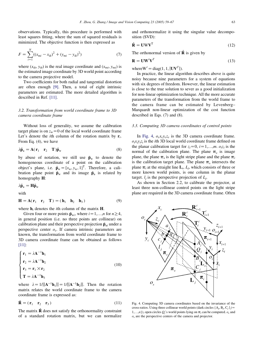
In Fig. 4, ocxcyczc is the 3D camera coordinate frame.
oixiyizi is the ith 3D local world coordinate frame defined on
the planar calibration target for ziZ0, iZ1,.,m. oizi is the
normal of the calibration plane. The plane pc is image
plane, the plane ps is the light stripe plane and the plane pi
is the calibration target plane. The plane ps intersects the
plane pi at the straight line Ls. Lj, which consists of three or
more known world points, is one column in the planar
target. lj is the perspective projection of Lj.
As shown in Section 2.2, to calibrate the projector, at
least three non-collinear control points on the light stripe
plane are required in the 3D camera coordinate frame. Often
Fig. 4. Computing 3D camera coordinates based on the invariance of the
cross-ratios. Using three collinear world points (dark circles {Aj, Bj, Cj j jZ
1,.,n}), open circles Qj’s world points lying on pi can be computed. oc and
os are the perspective centers of the camera and projector.
�
64
F. Zhou, G. Zhang / Image and Vision Computing 23 (2005) 59–67
more control points are necessary to improve the calibration
accuracy. Therefore, we must obtain the 3D camera
coordinates of the control points lying on Ls prior to
projector calibration.
Under perspective projection, the length or two lengths’
ratio will change, but the ratio of two ratios, which is called
the cross-ratios, remains unchanged. That is to say, the four
collinear points (Aj,Qj,Bj,Cj) and their projected points in the
images plane (aj,qj,bj,cj) have the same cross-ratios. The
cross-ratio is defined as:
rðAj
; Qj
; Bj
; CjÞ Z AjBj
QjBj
:
AjCj
QjCj
Z ajbj
qjbj
:
ajcj
qjcj
(14)
where jZ1,.,n.
The image coordinates of the points aj, qj, bj, cj can be
estimate with sub-pixel accuracy by image processing. Then
the normalized image coordinates of the points aj, qj, bj, cj
can be obtained from their corresponding image coordinates
according to camera model. As shown in Fig. 4, the known
collinear world points Aj, Bj, Cj do not fall onto ps, the world
coordinate of the control point Qj that falls on ps can be
computed according to Eq.
(14). Then the camera
coordinates of the control points Qj can be computed from
their corresponding world coordinates based on Eq. (1).
We only obtain the collinear control points if we use one
view of the planar calibration target from an arbitrary
orientation. Therefore, we must construct the calibration
control points by using multiple views of the same planar
calibration target from the different orientations. All views
of the calibration plane are acquired by one camera in the
different positions.
Zð xi
We use m views of the captured planar target image with
1ÞT
n control points for each view. Let ~pi
1ÞT be the homogeneous coordi-
j
and ~pi
cj
nate of the jth control point in the ith local world coordinate
frame and its camera coordinate, respectively, where iZ
1wm, jZ1wn.
Zð xi
yi
cj
zi
cj
yi
j
zi
j
cj
j
onto the light stripe plane, and their corresponding normal-
ized image coordinates.
Hc
i and ~pi
j are determined, ~pi
cj for all the control points
lying on the different views, respectively, can be computed
according to (14).
Theoretically speaking, as the scheme described above,
many non-collinear control points lying on the light stripe
plane can be constructed by viewing the same planar
calibration target
from multiple unknown different
orientations.
The camera coordinates of all the non-collinear control
points lying on the light stripe plane and their corresponding
normalized image coordinates can be denoted as follows.
i ~pi
ZgHc
j Q ZgQi
~pi
cj
where iZ1wm, jZ1wn. Qi
j is the normalized coordinate of
images of the jth control points respective to the ith view.
(16)
j
3.4. Projector calibration
An arbitrary number of control points (xci, yci, zci) (iZ
1,.,k) on the structured light stripe plane can easily be
obtained as scheme described above. Use Eq. (6) to fit the k
control points with the nonlinear
least squares. The
objective function is the square sum of the distance from
the control points to the fitted plane:
X
k
fðxÞ Z
iZ1
d2
i
;
i Z 1.k
(17)
xZ(a,b,c,d),
where
di
Zjaxci
C byci
C czci
C dj=ða2 C b2 C c2Þ1=2
After the camera and projector calibration are completed,
we can reconstruct the metric 3D camera coordinates from
the 2D real image points based on Eqs. (4)–(6).
3.5. Summary
The 3D camera coordinates of the non-collinear control
points can be computed from their local world coordinates
frame as follows.
In summary, for the light stripe plane illuminated from
the projector, the procedure for the proposed calibration
method is as follows:
!
~pi
cj
Z Hc
i ~pi
j
where
Z
Hc
i
Rc
i Tc
i
0T
1
is 4!4 transformation matrix, which relates the ith local
world coordinate frame to the 3D camera coordinate frame.
is 3!3 orthogonal
Tc
i
rotation matrix.
is 3!1 translation vector and Rc
i
Hc
i is estimated as the scheme described in Section 3.2
with additional at least six the known world points for each
view, which fall onto the calibration target and don’t fall
(15)
(1) Extracting all the image coordinates of the light stripe
(2) Correcting the distortion for those image coordinates
according to Eq. (5)
(3) Fitting the feature line with the image coordinates of
undistorted image coordinates obtained in (2).
(4) Fitting the straight lines with the undistorted image
coordinates of the known world collinear points (at
least three) with lying on the planar calibration target
but not falling on the light stripe plane.
(5) Computing the intersection points of the feature line
and the fitted lines in (4), respectively.
(6) Computing the normalized image coordinates of the
control points which are computed in (5) according to
Eq. (3).
�
F. Zhou, G. Zhang / Image and Vision Computing 23 (2005) 59–67
65
Fig. 5. Designed structured light vision sensor.
(7) Computing the cross-ratio as given by Eq. (14) for
each image line lj and computing the local world
coordinates.
(8) Computing the ith transformation Hc
i with another
feature points lying on the ith calibration plane but not
on the light stripe and their corresponding image
coordinates.
(9) Computing the 3D camera coordinates of the control
points.
(10) Estimating the equation of the light stripe plane in 3D
camera coordinate frame as described in Section 3.4.
Because our method uses unknown orientation planar
calibration target, the proposed calibration method can be
easily extended to handle an arbitrary large number of
control points. The calibration is very easy and flexible.
4. Experiments
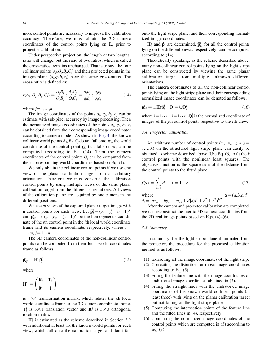
We designed a structured light vision sensor, which is
shown in Fig. 5. The sensor consists of an off-the-shelf
WATEC CCD camera (902H) with 16 mm lens and a stripe
laser projector (wave length, 650 nm, line width %1 mm).
The image resolution is 768!576. The distance between
the camera and the laser projector is about 500 mm. The
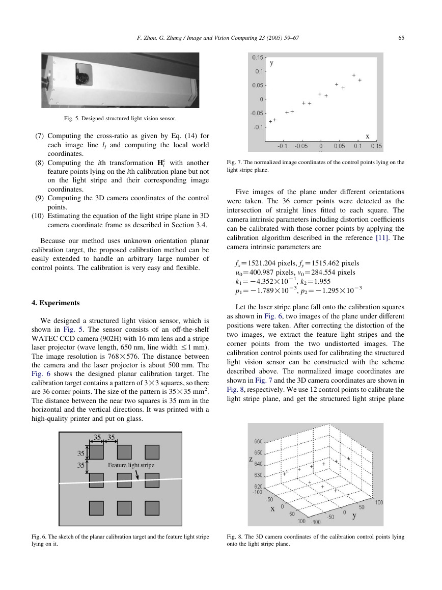
Fig. 6 shows the designed planar calibration target. The
calibration target contains a pattern of 3!3 squares, so there
are 36 corner points. The size of the pattern is 35!35 mm2.
The distance between the near two squares is 35 mm in the
horizontal and the vertical directions. It was printed with a
high-quality printer and put on glass.
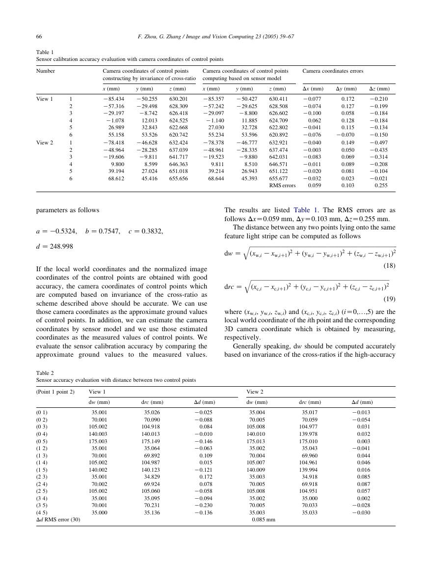
Fig. 7. The normalized image coordinates of the control points lying on the
light stripe plane.
Five images of the plane under different orientations
were taken. The 36 corner points were detected as the
intersection of straight lines fitted to each square. The
camera intrinsic parameters including distortion coefficients
can be calibrated with those corner points by applying the
calibration algorithm described in the reference [11]. The
camera intrinsic parameters are
fxZ1521.204 pixels, fyZ1515.462 pixels
u0Z400.987 pixels, v0Z284.554 pixels
k1ZK4.352!10
p1ZK1.789!10
K1, k2Z1.955
K3, p2ZK1.295!10
K3
Let the laser stripe plane fall onto the calibration squares
as shown in Fig. 6, two images of the plane under different
positions were taken. After correcting the distortion of the
two images, we extract the feature light stripes and the
corner points from the two undistorted images. The
calibration control points used for calibrating the structured
light vision sensor can be constructed with the scheme
described above. The normalized image coordinates are
shown in Fig. 7 and the 3D camera coordinates are shown in
Fig. 8, respectively. We use 12 control points to calibrate the
light stripe plane, and get the structured light stripe plane
Fig. 6. The sketch of the planar calibration target and the feature light stripe
lying on it.
Fig. 8. The 3D camera coordinates of the calibration control points lying
onto the light stripe plane.
�
66
F. Zhou, G. Zhang / Image and Vision Computing 23 (2005) 59–67
Table 1
Sensor calibration accuracy evaluation with camera coordinates of control points
Number
View 1
View 2
1
2
3
4
5
6
1
2
3
4
5
6
Camera coordinates of control points
constructing by invariance of cross-ratio
Camera coordinates of control points
computing based on sensor model
Camera coordinates errors
x (mm)
K85.434
K57.316
K29.197
K1.078
26.989
55.158
K78.418
K48.964
K19.606
9.800
39.194
68.612
y (mm)
K50.255
K29.498
K8.742
12.013
32.843
53.526
K46.628
K28.285
K9.811
8.599
27.024
45.416
z (mm)
630.201
628.309
626.418
624.525
622.668
620.742
632.424
637.039
641.717
646.363
651.018
655.656
x (mm)
K85.357
K57.242
K29.097
K1.140
27.030
55.234
K78.378
K48.961
K19.523
9.811
39.214
68.644
y (mm)
K50.427
K29.625
K8.800
11.885
32.728
53.596
K46.777
K28.335
K9.880
8.510
26.943
45.393
z (mm)
630.411
628.508
626.602
624.709
622.802
620.892
632.921
637.474
642.031
646.571
651.122
655.677
RMS errors
Dx (mm)
K0.077
K0.074
K0.100
0.062
K0.041
K0.076
K0.040
K0.003
K0.083
K0.011
K0.020
K0.032
0.059
Dy (mm)
0.172
0.127
0.058
0.128
0.115
K0.070
0.149
0.050
0.069
0.089
0.081
0.023
0.103
Dz (mm)
K0.210
K0.199
K0.184
K0.184
K0.134
K0.150
K0.497
K0.435
K0.314
K0.208
K0.104
K0.021
0.255
parameters as follows
a Z K0:5324;
b Z 0:7547;
c Z 0:3832;
d Z 248:998
If the local world coordinates and the normalized image
coordinates of the control points are obtained with good
accuracy, the camera coordinates of control points which
are computed based on invariance of the cross-ratio as
scheme described above should be accurate. We can use
those camera coordinates as the approximate ground values
of control points. In addition, we can estimate the camera
coordinates by sensor model and we use those estimated
coordinates as the measured values of control points. We
evaluate the sensor calibration accuracy by comparing the
approximate ground values to the measured values.
Table 2
Sensor accuracy evaluation with distance between two control points
(Point 1 point 2)
View 1
dw (mm)
drc (mm)
(0 1)
(0 2)
(0 3)
(0 4)
(0 5)
(1 2)
(1 3)
(1 4)
(1 5)
(2 3)
(2 4)
(2 5)
(3 4)
(3 5)
(4 5)
Dd RMS error (30)
35.001
70.001
105.002
140.003
175.003
35.001
70.001
105.002
140.002
35.001
70.002
105.002
35.001
70.001
35.000
35.026
70.090
104.918
140.013
175.149
35.064
69.892
104.987
140.123
34.829
69.924
105.060
35.095
70.231
35.136
Dd (mm)
K0.025
K0.088
0.084
K0.010
K0.146
K0.063
0.109
0.015
K0.121
0.172
0.078
K0.058
K0.094
K0.230
K0.136
The results are listed Table 1. The RMS errors are as
follows DxZ0.059 mm, DyZ0.103 mm, DzZ0.255 mm.
The distance between any two points lying onto the same
feature light stripe can be computed as follows
q
K xw;iC1Þ2 Cðyw;i
ffiffiffiffiffiffiffiffiffiffiffiffiffiffiffiffiffiffiffiffiffiffiffiffiffiffiffiffiffiffiffiffiffiffiffiffiffiffiffiffiffiffiffiffiffiffiffiffiffiffiffiffiffiffiffiffiffiffiffiffiffiffiffiffiffiffiffiffiffiffiffiffiffiffiffiffiffiffiffiffiffiffiffiffiffiffiffiffiffiffiffiffiffiffiffiffiffiffiffi
ðxw;i
K zw;iC1Þ2
q
ffiffiffiffiffiffiffiffiffiffiffiffiffiffiffiffiffiffiffiffiffiffiffiffiffiffiffiffiffiffiffiffiffiffiffiffiffiffiffiffiffiffiffiffiffiffiffiffiffiffiffiffiffiffiffiffiffiffiffiffiffiffiffiffiffiffiffiffiffiffiffiffiffiffiffiffiffiffiffiffiffiffiffiffiffiffiffiffiffiffiffiffiffi
K zc;iC1Þ2
ðxc;i
K yw;iC1Þ2 Cðzw;i
K xc;iC1Þ2 Cðyc;i
K yc;iC1Þ2 Cðzc;i
(18)
dw Z
drc Z
(19)
where (xw,i, yw,i, zw,i) and (xc,i, yc,i, zc,i) (iZ0,.,5) are the
local world coordinate of the ith point and the corresponding
3D camera coordinate which is obtained by measuring,
respectively.
Generally speaking, dw should be computed accurately
based on invariance of the cross-ratios if the high-accuracy
View 2
dw (mm)
35.004
70.005
105.008
140.010
175.013
35.002
70.004
105.007
140.009
35.003
70.005
105.008
35.002
70.005
35.003
0.085 mm
drc (mm)
35.017
70.059
104.977
139.978
175.010
35.043
69.960
104.961
139.994
34.918
69.918
104.951
35.000
70.033
35.033
Dd (mm)
K0.013
K0.054
0.031
0.032
0.003
K0.041
0.044
0.046
0.016
0.085
0.087
0.057
0.002
K0.028
K0.030
�


 2023年江西萍乡中考道德与法治真题及答案.doc
 2012年重庆南川中考生物真题及答案.doc
 2013年江西师范大学地理学综合及文艺理论基础考研真题.doc
 2020年四川甘孜小升初语文真题及答案I卷.doc
 2020年注册岩土工程师专业基础考试真题及答案.doc
 2023-2024学年福建省厦门市九年级上学期数学月考试题及答案.doc
 2021-2022学年辽宁省沈阳市大东区九年级上学期语文期末试题及答案.doc
 2022-2023学年北京东城区初三第一学期物理期末试卷及答案.doc
 2018上半年江西教师资格初中地理学科知识与教学能力真题及答案.doc
 2012年河北国家公务员申论考试真题及答案-省级.doc
 2020-2021学年江苏省扬州市江都区邵樊片九年级上学期数学第一次质量检测试题及答案.doc
 2022下半年黑龙江教师资格证中学综合素质真题及答案.doc