®
APPLICATION BULLETIN
Mailing Address: PO Box 11400 • Tucson, AZ 85734 • Street Address: 6730 S. Tucson Blvd. • Tucson, AZ 85706
Tel: (602) 746-1111 • Twx: 910-952-111 • Telex: 066-6491 • FAX (602) 889-1510 • Immediate Product Info: (800) 548-6132
OPERATIONAL AMPLIFIER MACROMODELS: A COMPARISON
By Bonnie Baker (602) 746-7468
All major competitors in the operational amplifier markets
are providing their customers Spice-based macromodels.
These models give the designer a tool to do initial character-
ization and a limited amount of system troubleshooting. In
the interest of faster simulation times and lower CPU memory
requirements, macro topologies have been developed to
simulate a majority of the op amp’s performance character-
istics. Several different approaches to creating macromodels
have been used, each producing a macro with its own set of
strengths and weaknesses. Circuit simulations have become
increasingly important to the systems level designer. By
using macros, the designer can quickly determine gross
limitations of their design and correct potential problems in
the circuit quickly at the computer terminal. Although it is
not recommended that circuit simulation replace the bread
board, many costly design problems can be quickly identi-
fied during the simulation cycle. By using a macromodel as
a simulation tool, the designer may be able to shorten the
design cycle of their circuit. This, of course, assumes that the
model’s level of accuracy is adequate for the design’s
constraints and trade offs. If the systems designer is aware of
the capabilities and limitations of the macro that has been
selected for the simulation phase, the entire design cycle can
be significantly reduced. Many of the macro’s limitations
can also be overcome with easily implemented enhance-
ments to the basic macromodel architecture, depending on
the specific application requirements. A good selection of
the correct model with appropriate enhancements enables
the designer to use the op amp macromodel as an effective
tool in system level circuit design.
Historically, circuit simulation tools, such as SPICE(1), were
developed for the integrated circuit designer. SPICE uses
detailed mathematical formulas, which emulate the behavior
of actual devices. The IC designer uses simulation tools,
such as SPICE, extensively during the circuit design cycle.
The level of sophistication that the IC circuit designer
requires is that every element is simulated as closely to
actual performance as possible. As a consequence, the ma-
jority of elements in the simulated circuit are non-linear
elements, such as bipolar transistors, field-effect transistors,
etc. Because of the complex behavior of these non-linear
elements in the Spice simulation environment, these ele-
ments require more simulation time and computer memory.
With increased integrated circuit complexity, performance
and size, simulation time and computer memory have be-
come critical simulation constraints for the software and
systems used by the IC designer.
This limitation has prevented the systems level designer
from taking full advantage of the same simulation tools. As
a result, macros have gained popularity as an alternative tool
for circuit simulation at the systems level. Op amp macros
are designed to model specific, predetermined amplifier
characteristics. When Spice is used as the preferred soft-
ware, the op amp macro is typically developed with one of
two basic design approaches.
ISS
RP
D1
+
V5
V3
+
D2
D3
+
V4
+In
–In
14
J1
J2
15
C1
16
R3
R4
+
V7
V+
22
Out
D4
D5
R2
C2
R1
C3
+
V6
RO1
G1
R5
G2
+
V1
+
V2
+
V8
G3
V–
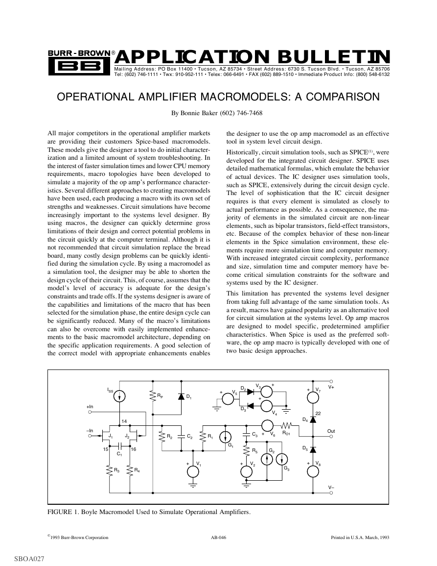
FIGURE 1. Boyle Macromodel Used to Simulate Operational Amplifiers.
©1993 Burr-Brown Corporation
AB-046
Printed in U.S.A. March, 1993
SBOA027
�
MACROMODEL DESIGN APPROACHES
The first basic macromodel design approach involves reduc-
ing the complexity of the circuit. For example, the input
stage of an op amp can be reduced to a differential pair with
a resistive load, biased with a current source. The actual
op amp could have a cascoded differential input with active
load and the current source biasing the input stage would be
built using a transistor that would have the non-linearities
associated with early voltage and collector resistance, etc.
Throughout the macromodel circuit, transistors that are
deemed non-critical are replaced with linear elements, such
as current sources, resistors, etc. The reduction in complex-
ity reduces the number of nodes in the circuit as well as the
number of non-linear devices, both of which will reduce
simulation time. To reduce simulation time even further, the
transistors are as near to ideal as possible. This is done
by reducing the number of transistor model parameters. The
obvious benefit of this macromodel design approach is a
reduction in simulation time; however, op amp performance
is compromised to some extent. For example, the input stage
of the model described does not model the common-mode
input range of the amplifier properly.
A second method that is used in macromodelling is the build
method. When this method is used, the designer of the macro
characterizes the performance of the op amp and then builds
the macro out of ideal linear elements, such as resistors,
inductors, capacitors, dependent sources and independent
sources. A good example of this topology would be the op
amp hybrid pi-model where the input stage of the amplifier
is a resistor. The voltage across that resistor is sensed by the
gain stage, etc. The simulation time of this type of model is
significantly faster than the first macromodel design method;
however, the op amp performance is compromised to a great
extent with this approach.
THE BOYLE OP AMP MACROMODEL
The Boyle Op Amp Macromodel(2) was designed using the
simplification method to design the input stage and the build
method for the remainder of the macro design. As shown in
+In
–In
ISS
R1
R2
CDIF
VOS
J1
J2
5
6
C1
R3
R4
V1
G1
G3
G5
C8
L1
G7
R13
G9
C2
R5
R7
C4
R9
C6
R11
D1
D2
V2
21
71
31
41
51
R14
L3
G2
G4
G6
C3
R6
R8
C5
R10
C7
G8
R15
L4
G10
R12
C9
L2
R16
7
R17
61
R18
4
Input Stage
Gain Stage
Center
Reference
Pole Stage
Pole/Zero
Stage
Zero/Pole
Stage
Common-Mode
Gain Stage
7
4
D3
D4
G11
D5
G12
D7
D8
91
D6
Ouput Stage
G13
V93
V94
R19
L3
G14
R20
Out
V+
V–
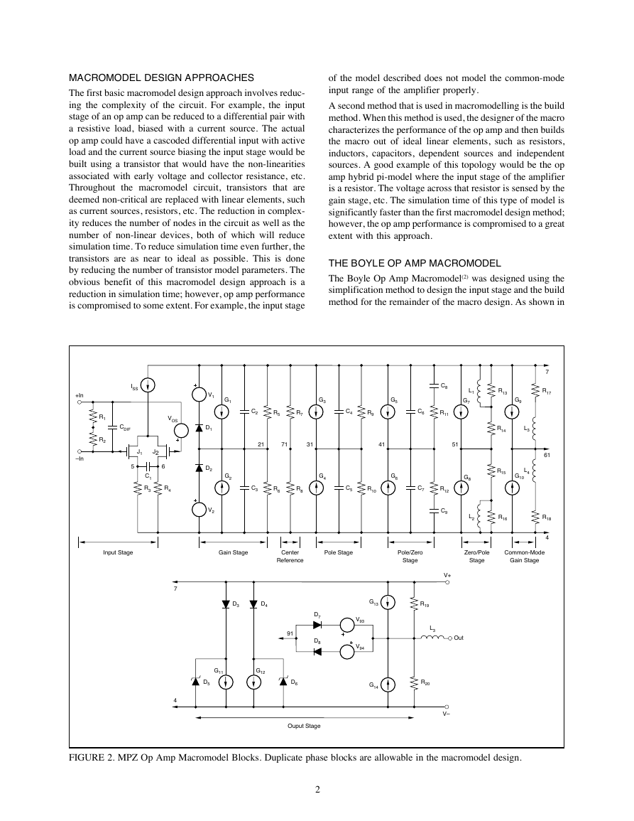
FIGURE 2. MPZ Op Amp Macromodel Blocks. Duplicate phase blocks are allowable in the macromodel design.
2
�
Figure 1, the only transistors in the Boyle model are used for
the input differential pair of the op amp. All other elements
are linear devices with the exception of a few diodes that are
used as clamps. The ac parameters that this model topology
simulates are slew rate, unity gain frequency, gain/phase for
a one or two pole amplifier and a simplified ac output
resistance. DC characteristics modelled are quiescent cur-
rent, short circuit output current, output voltage swing maxi-
mums and minimums, input bias current, common-mode
rejection ratio, and dc output resistance. The Boyle
macromodel performance characteristics listed above suf-
fice for many general applications. However, temperature
performance, common-mode input range, offset voltage,
offset current, input protection, power supply rejection,
noise, THD, input impedance, good ac output resistance, and
change in supply current versus supply voltage are a few of
the more important parameters that are not modelled with
the Boyle macro topology. Several op amp vendors have
chosen to design their macros around the Boyle topology. Of
the companies using the Boyle model that were researched,
all added enhancements to the Boyle model to include a few
more operational amplifier performance features.
THE MULTIPLE POLE/ZERO MACROMODEL
Another popular topology using both macromodelling meth-
ods is shown in Figure 2. The model shown in Figure 2 and
the Boyle model (Figure 1) have identical input stages, but
all of the remaining stages are different. This topology
evolved from several sources(3,4) and is named after the mid-
section of the model, multiple pole/zero or MPZ. The mid-
section of this model can be expanded to include additional
poles, pole-zero, or zero-pole stages. The MPZ macro has
the same dc performance characteristics as the Boyle model
as well as input offset bias current, input offset voltage and
input differential impedance. The ac parameters that this
model topology simulates are slew rate, unity gain fre-
quency, gain/phase for a multiple pole/zero amplifier, CMRR
versus frequency, and a simplified ac output resistance. In
addition, the MPZ macro models change in quiescent cur-
rent versus change in supply voltage, has no ground refer-
ence, and splits the output current between the supplies
instead of sinking and sourcing from ground. A few of the
MPZ limitations are a lack of temperature performance,
poor modelling of common-mode input range, no input
protection circuitry, no power supply rejection, no noise, no
THD, and the ac output resistance is modelled with a one
zero system.
THE BOYLE MACROMODEL
VERSUS THE MPZ MACROMODEL
When comparing op amp macro performance, there are two
simulation characteristics that are critical to the systems
designer. The macro must model the electrical performance
of the op amp in the designer’s application of interest, and
secondly, the macro must perform the simulation in a rea-
sonable amount of time using a reasonable amount of com-
puter memory.
When comparing the electrical performance of the Boyle
model versus the MPZ model, the MPZ model provides
several additional performance characteristics that the Boyle
does not. For instance, the MPZ model models the same DC
parameters that the Boyle model does and additionally input
offset voltage and input offset bias current. The MPZ macro
lacks a reference to ground which is sometimes convenient
in level shift circuits where the Boyle model has several
ground references in the circuit. Additionally, the MPZ
macro draws output current from the supplies' nodes instead
of the ground node. This is useful when power supply
requirements are evaluated. The real power of the MPZ
macro, however, is in the ac domain. If an op amp has more
than two poles and/or additional pole/zero pairs in its trans-
fer function, the Boyle model is unable to do an adequate job
simulating the op amp.
V1
OPA27
RG
R
R
Out
R
R
OPA27
V2
VOUT = 2(1 + R/RG)(V1–V2)
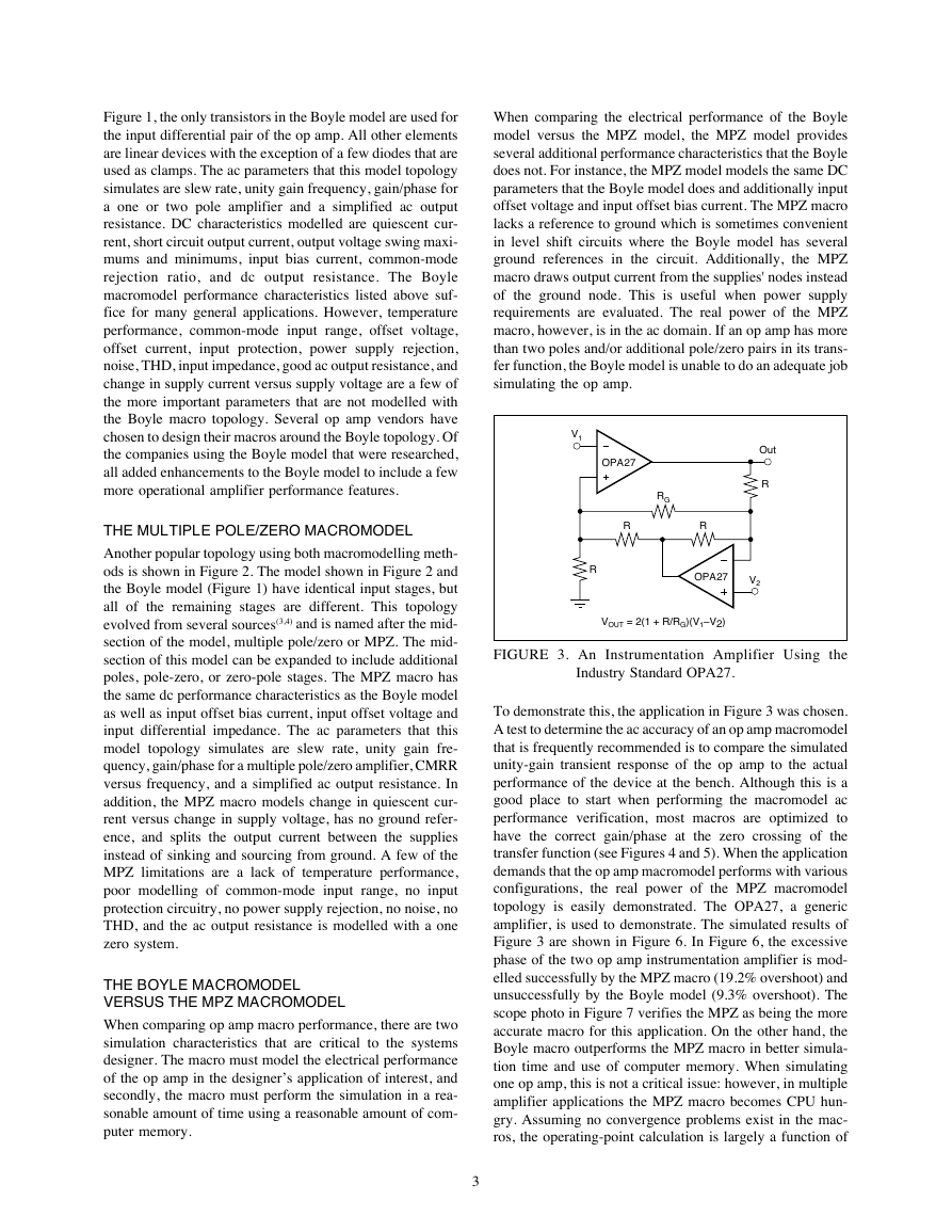
FIGURE 3. An Instrumentation Amplifier Using the
Industry Standard OPA27.
To demonstrate this, the application in Figure 3 was chosen.
A test to determine the ac accuracy of an op amp macromodel
that is frequently recommended is to compare the simulated
unity-gain transient response of the op amp to the actual
performance of the device at the bench. Although this is a
good place to start when performing the macromodel ac
performance verification, most macros are optimized to
have the correct gain/phase at the zero crossing of the
transfer function (see Figures 4 and 5). When the application
demands that the op amp macromodel performs with various
configurations, the real power of the MPZ macromodel
topology is easily demonstrated. The OPA27, a generic
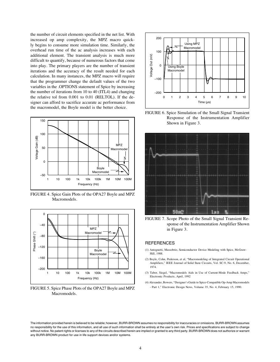
amplifier, is used to demonstrate. The simulated results of
Figure 3 are shown in Figure 6. In Figure 6, the excessive
phase of the two op amp instrumentation amplifier is mod-
elled successfully by the MPZ macro (19.2% overshoot) and
unsuccessfully by the Boyle model (9.3% overshoot). The
scope photo in Figure 7 verifies the MPZ as being the more
accurate macro for this application. On the other hand, the
Boyle macro outperforms the MPZ macro in better simula-
tion time and use of computer memory. When simulating
one op amp, this is not a critical issue: however, in multiple
amplifier applications the MPZ macro becomes CPU hun-
gry. Assuming no convergence problems exist in the mac-
ros, the operating-point calculation is largely a function of
3
�
)
V
m
(
t
u
O
e
g
a
t
l
o
V
Using MPZ
Macromodel
Using Boyle
Macromodel
200
100
0
–100
–200
0
1
2
3
4
5
6
7
8
9
10
Time (µs)
FIGURE 6. Spice Simulation of the Small Signal Transient
Response of the Instrumentation Amplifier
Shown in Figure 3.
the number of circuit elements specified in the net list. With
increased op amp complexity, the MPZ macro quick-
ly begins to consume more simulation time. Similarly, the
overhead run time of the ac analysis increases with each
additional element. The transient analysis is much more
difficult to quantify, because of numerous factors that come
into play. The primary players are the number of transient
iterations and the accuracy of the result needed for each
calculation. In many instances, the MPZ macro will require
that the programmer change the default values of the two
variables in the .OPTIONS statement of Spice by increasing
the number of iterations from 10 to 40 (ITL4) and changing
the relative tol from 0.001 to 0.01 (RELTOL). If the de-
signer can afford to sacrifice accurate ac performance from
the macromodel, the Boyle model is the better choice.
)
B
d
(
i
n
a
G
e
g
a
t
l
o
V
150
100
50
0
–50
MPZ
Macromodel
Boyle
Macromodel
1
10
100
1k
10k
100k
1M 10M 100M
Frequency (Hz)
FIGURE 4. Spice Gain Plots of the OPA27 Boyle and MPZ
Macromodels.
)
°
(
t
f
i
h
S
e
s
a
h
P
0
–40
–80
–120
–160
–200
MPZ
Macromodel
Boyle
Macromodel
FIGURE 7. Scope Photo of the Small Signal Transient Re-
sponse of the Instrumentation Amplifier Shown
in Figure 3.
REFERENCES
(1) Antognetti, Massobrio, Semiconductor Device Modeling with Spice, McGraw-
Hill, 1988.
(2) Boyle, Cohn, Pederson, et al, “Macromodeling of Integrated Circuit Operational
Amplifiers,” IEEE Journal of Solid State Circuits, Vol. SC-9, No. 6, December,
1974.
1
10
100
1k
10k
100k
1M 10M 100M
(3) Tabor, Siegel, “Macromodels Aids in Use of Current-Mode Feedback Amps,”
Frequency (Hz)
Electronic Products, April, 1992
FIGURE 5. Spice Phase Plots of the OPA27 Boyle and MPZ
Macromodels.
(4) Alexander, Bowers, “Designer’s Guide to Spice-Compatible Op-Amp Macromodels
- Part 1,” Electronic Design News, Volume 35, No. 4, February 15, 1990.
The information provided herein is believed to be reliable; however, BURR-BROWN assumes no responsibility for inaccuracies or omissions. BURR-BROWN assumes
no responsibility for the use of this information, and all use of such information shall be entirely at the user’s own risk. Prices and specifications are subject to change
without notice. No patent rights or licenses to any of the circuits described herein are implied or granted to any third party. BURR-BROWN does not authorize or warrant
any BURR-BROWN product for use in life support devices and/or systems.
4
�
IMPORTANT NOTICE
Texas Instruments and its subsidiaries (TI) reserve the right to make changes to their products or to discontinue
any product or service without notice, and advise customers to obtain the latest version of relevant information
to verify, before placing orders, that information being relied on is current and complete. All products are sold
subject to the terms and conditions of sale supplied at the time of order acknowledgment, including those
pertaining to warranty, patent infringement, and limitation of liability.
TI warrants performance of its semiconductor products to the specifications applicable at the time of sale in
accordance with TI’s standard warranty. Testing and other quality control techniques are utilized to the extent
TI deems necessary to support this warranty. Specific testing of all parameters of each device is not necessarily
performed, except those mandated by government requirements.
Customers are responsible for their applications using TI components.
In order to minimize risks associated with the customer’s applications, adequate design and operating
safeguards must be provided by the customer to minimize inherent or procedural hazards.
TI assumes no liability for applications assistance or customer product design. TI does not warrant or represent
that any license, either express or implied, is granted under any patent right, copyright, mask work right, or other
intellectual property right of TI covering or relating to any combination, machine, or process in which such
semiconductor products or services might be or are used. TI’s publication of information regarding any third
party’s products or services does not constitute TI’s approval, warranty or endorsement thereof.
Copyright 2000, Texas Instruments Incorporated
�


 2023年江西萍乡中考道德与法治真题及答案.doc
 2012年重庆南川中考生物真题及答案.doc
 2013年江西师范大学地理学综合及文艺理论基础考研真题.doc
 2020年四川甘孜小升初语文真题及答案I卷.doc
 2020年注册岩土工程师专业基础考试真题及答案.doc
 2023-2024学年福建省厦门市九年级上学期数学月考试题及答案.doc
 2021-2022学年辽宁省沈阳市大东区九年级上学期语文期末试题及答案.doc
 2022-2023学年北京东城区初三第一学期物理期末试卷及答案.doc
 2018上半年江西教师资格初中地理学科知识与教学能力真题及答案.doc
 2012年河北国家公务员申论考试真题及答案-省级.doc
 2020-2021学年江苏省扬州市江都区邵樊片九年级上学期数学第一次质量检测试题及答案.doc
 2022下半年黑龙江教师资格证中学综合素质真题及答案.doc