UPRGAM4096 manual
Manual
UPRGAM4096D01_01
Issue 1, 20th November 2009
Software installation
Download the software from www.rls.si/UPRGAM4096 by clicking the Documentation tab and selecting the file
UPRGAM4096_Software. Once downloaded open the Setup.exe file and follow the installation wizard to complete
installation.
NOTE – You should install the UPRGAM4096 software BEFORE connecting the UPRGAM4096 interface.
Note: Administrator rights are required to install the software.
Compatible operating systems: Windows XP, Windows Vista
Connecting the UPRGAM4096 interface and RMK4
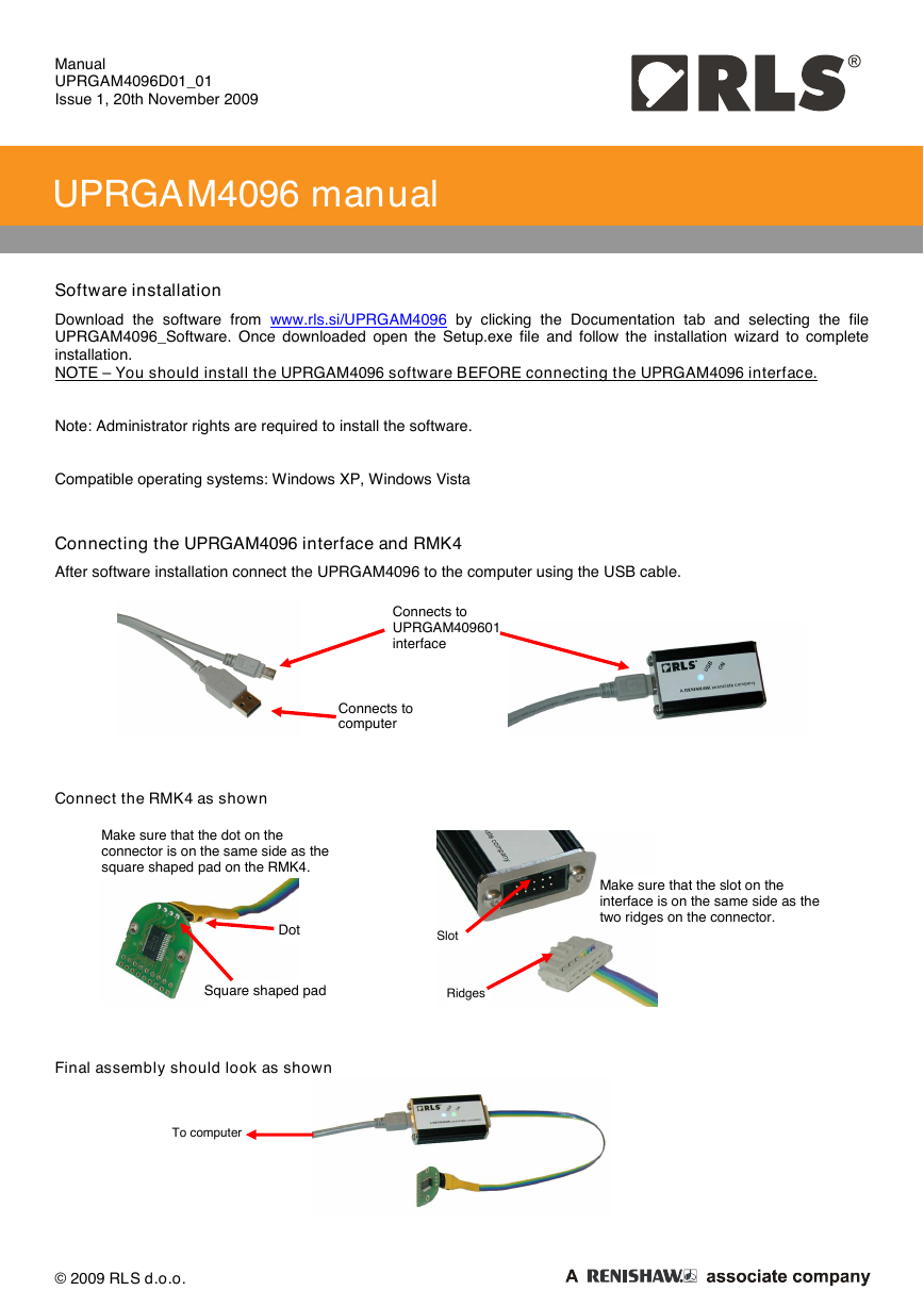
After software installation connect the UPRGAM4096 to the computer using the USB cable.
Connects to
UPRGAM409601
interface
Connects to
computer
Connect the RMK4 as shown
Make sure that the dot on the
connector is on the same side as the
square shaped pad on the RMK4.
Dot
Slot
Make sure that the slot on the
interface is on the same side as the
two ridges on the connector.
Ridges
Square shaped pad
Final assembly should look as shown
To computer
© 2009 RLS d.o.o.
�
Manual
UPRGAM4096D01_01
Issue 1, 20th November 2009
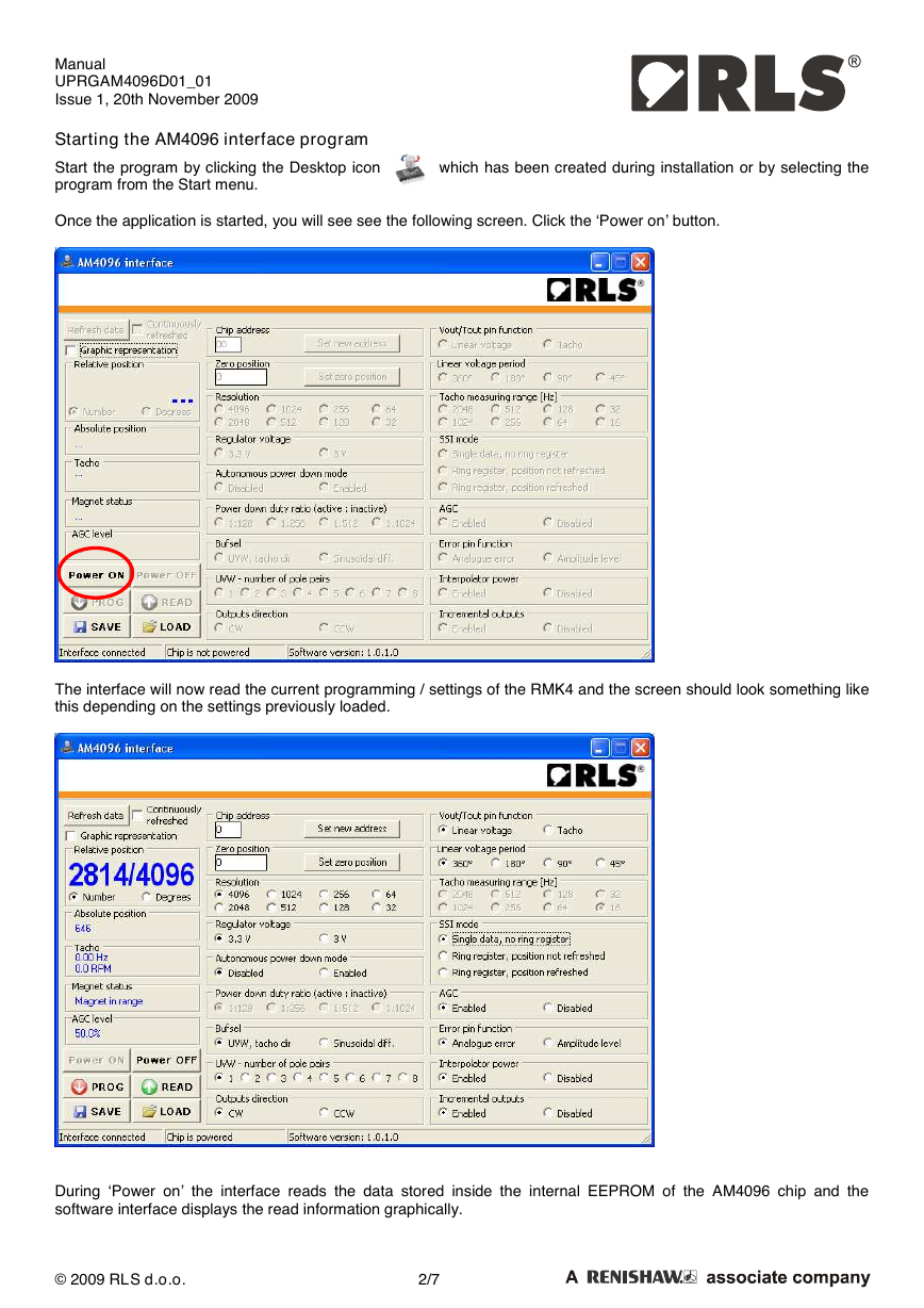
Starting the AM4096 interface program
Start the program by clicking the Desktop icon
program from the Start menu.
Once the application is started, you will see see the following screen. Click the ‘Power on’ button.
which has been created during installation or by selecting the
The interface will now read the current programming / settings of the RMK4 and the screen should look something like
this depending on the settings previously loaded.
During ‘Power on’ the interface reads the data stored inside the internal EEPROM of the AM4096 chip and the
software interface displays the read information graphically.
© 2009 RLS d.o.o.
2/7
�
Manual
UPRGAM4096D01_01
Issue 1, 20th November 2009
Programming and reading
The AM4096 can be re-programmed by changing the parameters within the software.
Once the desired parameters have been selected, the ‘PROG’ button has to be clicked in
order to save the changes to the chip.
The ‘READ’ button reads the current programming of the AM4096 chip. (If, for example, the parameters on the screen
have been changed, but not saved, and the current programming needs to be read again, this can be done by
pressing the ‘READ’ button.)
Different settings can be stored to the computer as a by pressing the ‘SAVE’ button. Previously saved setting can be
uploaded by pressing the ‘LOAD’ button.
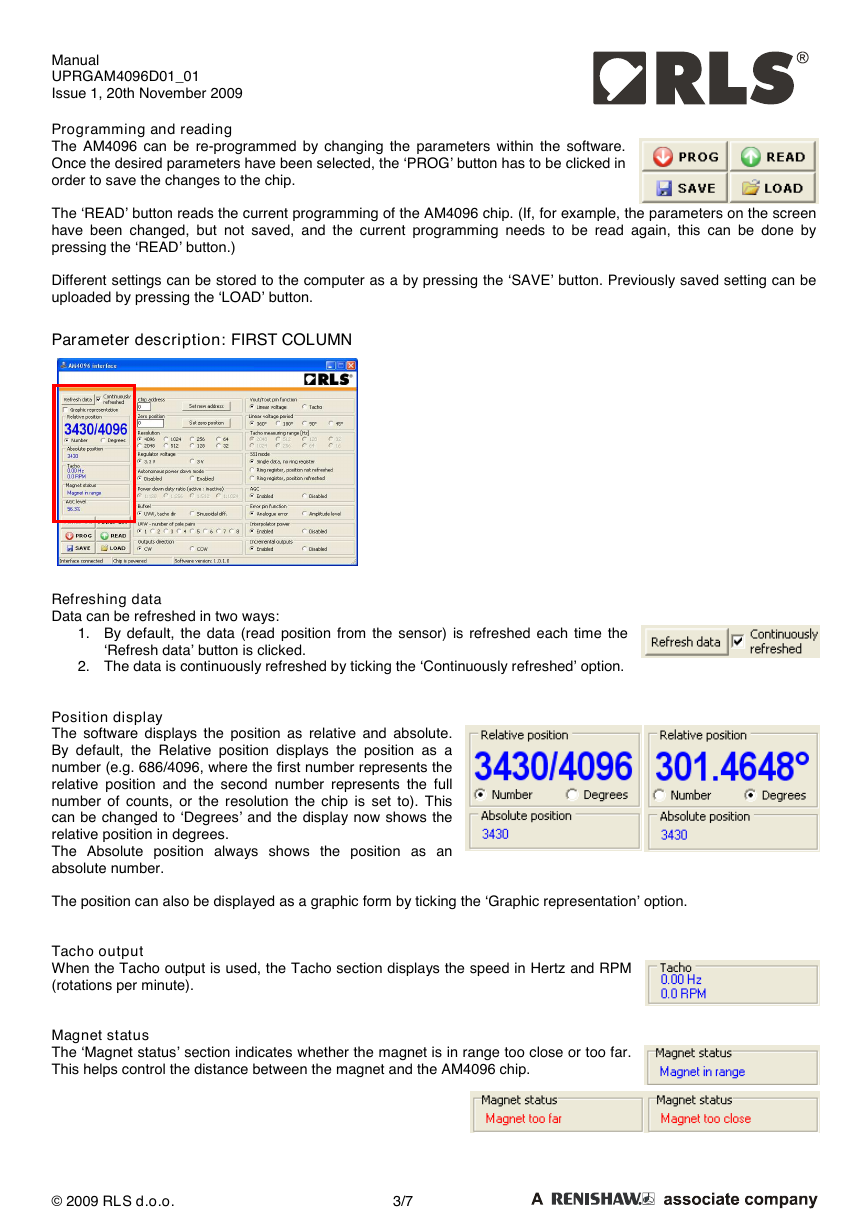
Parameter description: FIRST COLUMN
Refreshing data
Data can be refreshed in two ways:
1. By default, the data (read position from the sensor) is refreshed each time the
‘Refresh data’ button is clicked.
2. The data is continuously refreshed by ticking the ‘Continuously refreshed’ option.
Position display
The software displays the position as relative and absolute.
By default, the Relative position displays the position as a
number (e.g. 686/4096, where the first number represents the
relative position and the second number represents the full
number of counts, or the resolution the chip is set to). This
can be changed to ‘Degrees’ and the display now shows the
relative position in degrees.
The Absolute position always shows the position as an
absolute number.
The position can also be displayed as a graphic form by ticking the ‘Graphic representation’ option.
Tacho output
When the Tacho output is used, the Tacho section displays the speed in Hertz and RPM
(rotations per minute).
Magnet status
The ‘Magnet status’ section indicates whether the magnet is in range too close or too far.
This helps control the distance between the magnet and the AM4096 chip.
© 2009 RLS d.o.o.
3/7
�
Manual
UPRGAM4096D01_01
Issue 1, 20th November 2009
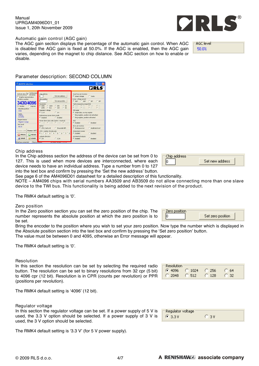
Automatic gain control (AGC gain)
The AGC gain section displays the percentage of the automatic gain control. When AGC
is disabled the AGC gain is fixed at 50.0%. If the AGC is enabled, then the AGC gain
varies, depending on the magnet to chip distance. See AGC section on how to enable or
disable.
Parameter description: SECOND COLUMN
Chip address
In the Chip address section the address of the device can be set from 0 to
127. This is used when more devices are interconnected, where each
device needs to have an individual address. Type a number from 0 to 127
into the text box and confirm by pressing the ‘Set the new address’ button.
See page 6 of the AM4096D01 datasheet for a detailed description of this functionality.
NOTE – AM4096 chips with serial numbers AA3509 and AB3509 do not allow connecting more than one slave
device to the TWI bus. This functionality is being added to the next revision of the product.
The RMK4 default setting is ‘0’.
Zero position
In the Zero position section you can set the zero position of the chip. The
number represents the absolute position at which the zero position is to
be set.
Bring the encoder to the position where you wish to set your zero position. Now type the number which is displayed in
the Absolute position section into the text box and confirm by pressing the ‘Set zero position’ button.
The value must be between 0 and 4095, otherwise an Error message will appear.
The RMK4 default setting is ‘0’.
Resolution
In this section the resolution can be set by selecting the required radio
button. The resolution can be set to binary resolutions from 32 cpr (5 bit)
to 4096 cpr (12 bit). Resolution is in CPR (counts per revolution) or PPR
(positions per revolution).
The RMK4 default setting is ‘4096’ (12 bit).
Regulator voltage
In this section the regulator voltage can be set. If a power supply of 5 V is
used, the 3.3 V option should be selected. If a power supply of 3 V is
used, the 3 V option should be selected.
The RMK4 default setting is ‘3.3 V’ (for 5 V power supply).
© 2009 RLS d.o.o.
4/7
�
Manual
UPRGAM4096D01_01
Issue 1, 20th November 2009
Autonomous power down mode and Power down duty ratio (active : inactive)
In this section the power save mode can be enabled or disabled by
selecting the appropriate button.
If enabled, the power down duty ratio can be selected. This means that
the position is not read continuously, but in intervals as selected.
The RMK4 default setting is ‘Disabled’.
Bufsel and UVW – number of pole pairs
In this section the output on pins 5, 6, 7 and 8 can be selected between
UVW/Tacho and differential sinusoidal.
If the UVW outputs are selected, the number of pole pairs of the UVW
commutation signals can be selected.
The RMK4 default setting is ‘UVW, tacho dir’ and the default number of
pole pairs is 1.
Outputs direction
In this section the output direction can be selected to be either CW
(clockwise) or CCW (counter clockwise).
The RMK4 default setting is ‘CW’.
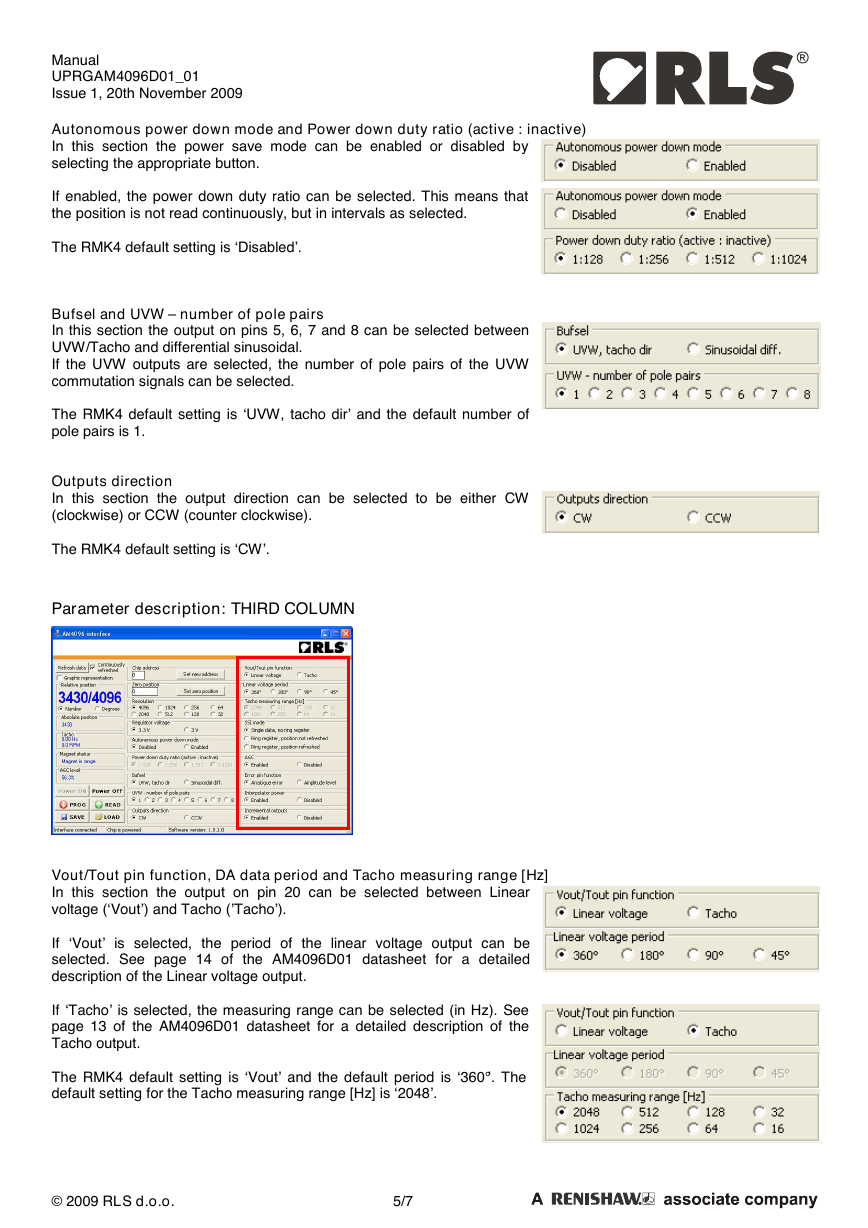
Parameter description: THIRD COLUMN
Vout/Tout pin function, DA data period and Tacho measuring range [Hz]
In this section the output on pin 20 can be selected between Linear
voltage (‘Vout’) and Tacho (’Tacho’).
If ‘Vout’ is selected, the period of the linear voltage output can be
selected. See page 14 of the AM4096D01 datasheet for a detailed
description of the Linear voltage output.
If ‘Tacho’ is selected, the measuring range can be selected (in Hz). See
page 13 of the AM4096D01 datasheet for a detailed description of the
Tacho output.
The RMK4 default setting is ‘Vout’ and the default period is ‘360°’. The
default setting for the Tacho measuring range [Hz] is ‘2048’.
© 2009 RLS d.o.o.
5/7
�
Manual
UPRGAM4096D01_01
Issue 1, 20th November 2009
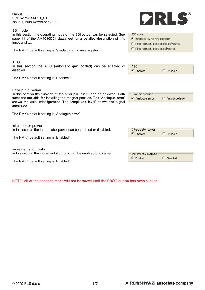
SSI mode
In this section the operating mode of the SSI output can be selected. See
page 11 of the AM4096D01 datasheet for a detailed description of this
functionality,.
The RMK4 default setting is ‘Single data, no ring register’.
AGC
In this section the AGC (automatic gain control) can be enabled or
disabled.
The RMK4 default setting is ‘Enabled’.
Error pin function
In this section the function of the error pin (pin 9) can be selected. Both
functions are aids for installing the magnet position. The ‘Analogue error’
shows the axial misalignment. The ‘Amplitude level’ shows the signal
amplitude.
The RMK4 default setting is ‘Analogue error’.
Interpolator power
In this section the interpolator power can be enabled or disabled.
The RMK4 default setting is ‘Enabled’.
Incremental outputs
In this section the incremental outputs can be enabled or disabled.
The RMK4 default setting is ‘Enabled’.
NOTE: All of the changes made will not be saved until the PROG button has been clicked.
© 2009 RLS d.o.o.
6/7
�
Manual
UPRGAM4096D01_01
Issue 1, 20th November 2009
Head office
RLS merilna tehnika d.o.o.
Cesta II. grupe odredov 25
SI-1261 Ljubljana - Dobrunje
T +386 1 5272100
F +386 1 5272129
E mail@rls.si
www.rls.si
Document issues
Issue
Date
Changes
1
20.11.2009
is our worldwide sales support partner for Magnetic Encoders.
Sweden
T +46 8 584 90 880
E sweden@renishaw.com
Switzerland
T +41 55 415 50 60
E
switzerland@renishaw.com
Taiwan
T +886 4 2251 3665
E taiwan@renishaw.com
UK
T +44 1453 524524
E uk@renishaw.com
USA
T +1 847 286 9953
E usa@renishaw.com
For all other countries
Please contact RLS' head
office
T +386 1 52 72 100
E mail@rls.si
Australia
T +61 3 9521 0922
E australia@renishaw.com
Austria
T +43 2236 379790
E austria@renishaw.com
Brazil
T +55 11 4195 2866
E brazil@renishaw.com
Canada
T +1 905 828 0104
E canada@renishaw.com
The People’s Republic of China
T +86 10 8448 5306
E beijing@renishaw.com
Czech Republic
T +420 5 4821 6553
E czech@renishaw.com
France
T +33 1 64 61 84 84
E france@renishaw.com
RLS merilna tehnika d.o.o. has made considerable effort to ensure the content of this document is correct at the date of publication but makes no
warranties or representations regarding the content. RLS merilna tehnika d.o.o. excludes liability, howsoever arising, for any inaccuracies in this
document.
The Netherlands
T +31 76 543 11 00
E benelux@renishaw.com
Poland
T +48 22 577 11 80
E poland@renishaw.com
Russia
T +7 095 231 16 77
E russia@renishaw.com
Singapore
T +65 6897 5466
E singapore@renishaw.com
Slovenia (Head Office)
T +386 1 52 72 100
E mail@rls.si
South Korea
T +82 2 2108 2830
E southkorea@renishaw.com
Spain
T +34 93 663 34 20
E spain@renishaw.com
Germany
T +49 7127 9810
E germany@renishaw.com
Hong Kong
T +852 2753 0638
E hongkong@renishaw.com
Hungary
T +36 23 502 183
E hungary@renishaw.com
India
T +91 80 2532 0144
E india@renishaw.com
Israel
T +972 4 953 6595
E israel@renishaw.com
Italy
T +39 011 966 10 52
E italy@renishaw.com
Japan
T +81 3 5366 5316
E japan@renishaw.com
© 2009 RLS d.o.o.
7/7
�


 2023年江西萍乡中考道德与法治真题及答案.doc
 2012年重庆南川中考生物真题及答案.doc
 2013年江西师范大学地理学综合及文艺理论基础考研真题.doc
 2020年四川甘孜小升初语文真题及答案I卷.doc
 2020年注册岩土工程师专业基础考试真题及答案.doc
 2023-2024学年福建省厦门市九年级上学期数学月考试题及答案.doc
 2021-2022学年辽宁省沈阳市大东区九年级上学期语文期末试题及答案.doc
 2022-2023学年北京东城区初三第一学期物理期末试卷及答案.doc
 2018上半年江西教师资格初中地理学科知识与教学能力真题及答案.doc
 2012年河北国家公务员申论考试真题及答案-省级.doc
 2020-2021学年江苏省扬州市江都区邵樊片九年级上学期数学第一次质量检测试题及答案.doc
 2022下半年黑龙江教师资格证中学综合素质真题及答案.doc