RDA Microelectronics, Inc. RDA5875 编程指南_v1.0
RDA5876 编程指南
AUTHER
CHANGE DESCRIPTION
马千里
马千里
Initial version.
Change for bb test
DATE
2012-4-13
2012-10-26
REV
V1.0
V1.3
上电配置顺序
5875 RF I2C协议
5875 Core I2C协议
I2C地址配置
UART波特率配置
UART流控配置
PCM接口配置
TM配置
共用晶体配置
32K时钟输入pin配置
睡眠握手机制配置
蓝牙地址配置
PSKEY配置说明
寄存器读写说明
DUT测试模式进入
非调制信号输出
调制信号输出
The information contained herein is the exclusive property of RDA and shall not be distributed, reproduced, or disclosed in whole or in
part without prior written permission of RDA.
Page 1 of 26
�
RDA Microelectronics, Inc. RDA5875 编程指南_v1.0
上电配置顺序:
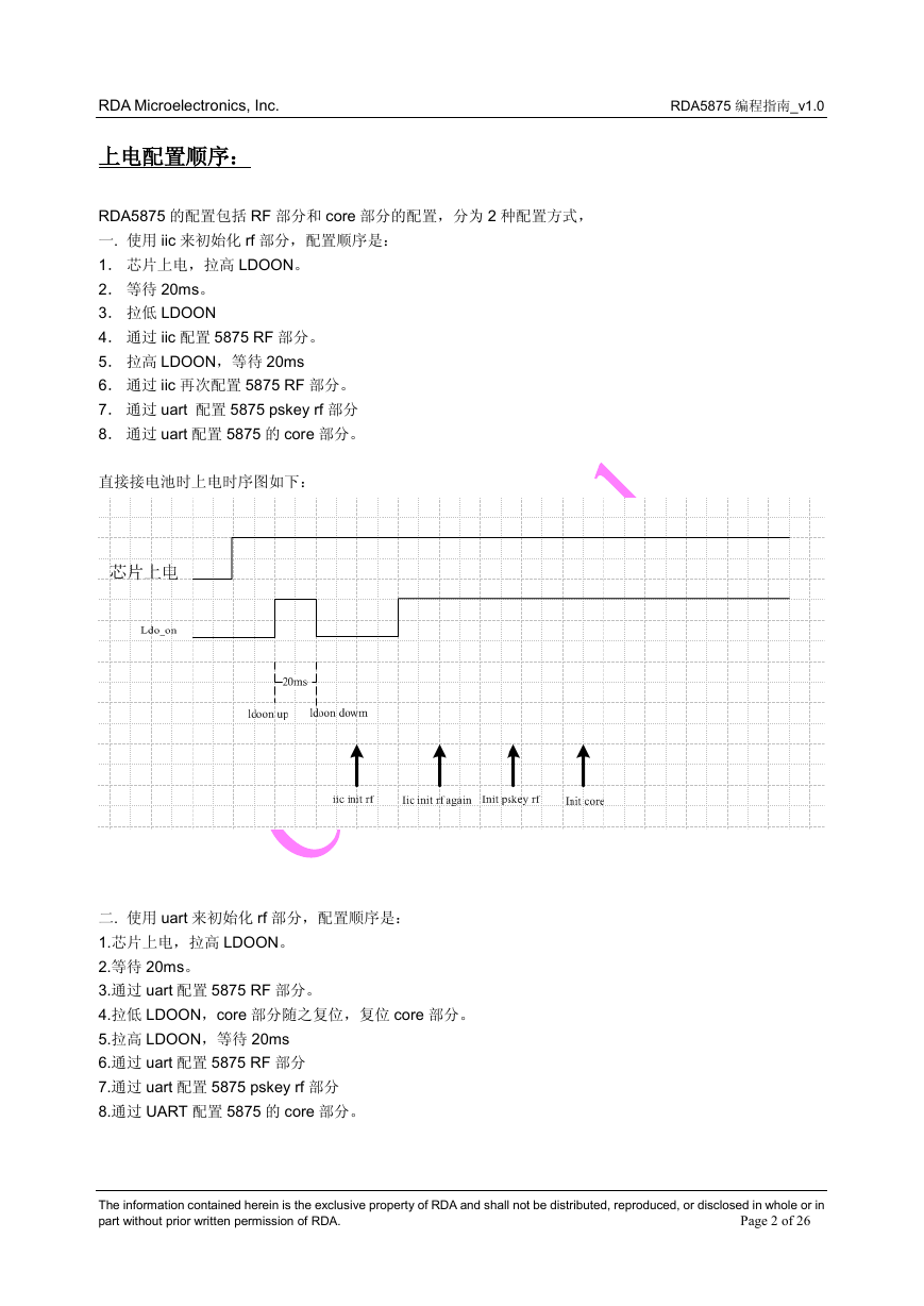
RDA5875 的配置包括 RF 部分和 core 部分的配置,分为 2 种配置方式,
一. 使用 iic 来初始化 rf 部分,配置顺序是:
1. 芯片上电,拉高 LDOON。
2. 等待 20ms。
3. 拉低 LDOON
4. 通过 iic 配置 5875 RF 部分。
5. 拉高 LDOON,等待 20ms
6. 通过 iic 再次配置 5875 RF 部分。
7. 通过 uart 配置 5875 pskey rf 部分
8. 通过 uart 配置 5875 的 core 部分。
直接接电池时上电时序图如下:
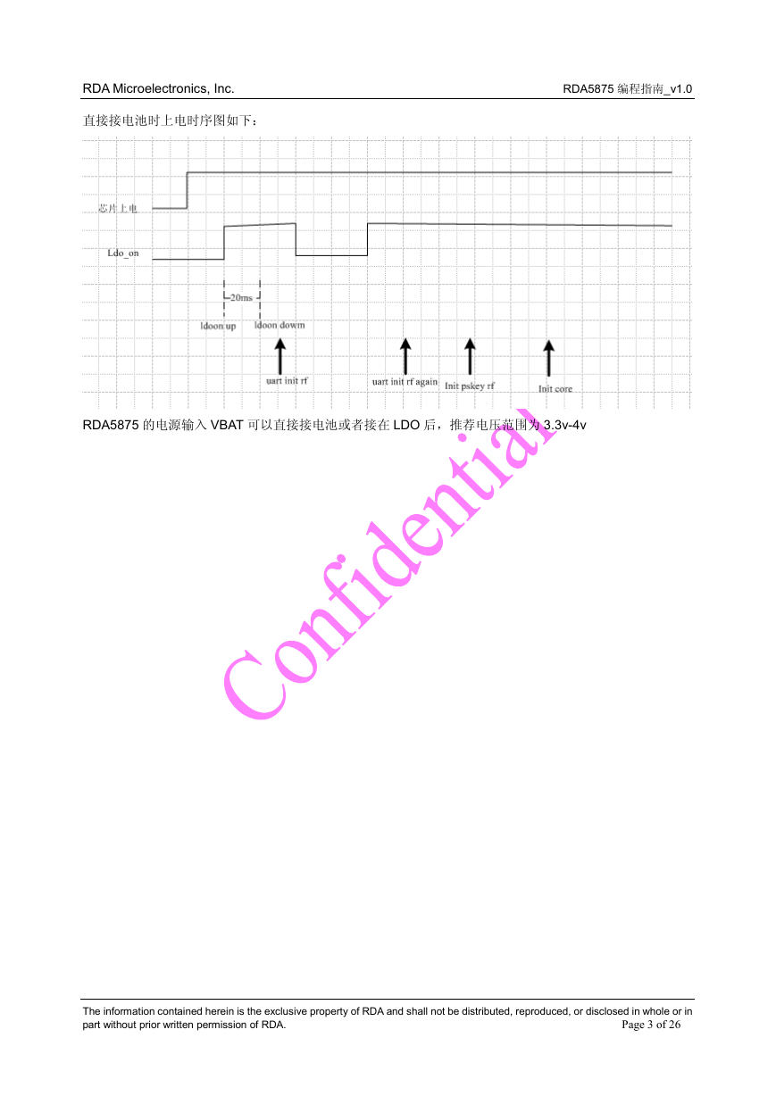
二. 使用 uart 来初始化 rf 部分,配置顺序是:
1.芯片上电,拉高 LDOON。
2.等待 20ms。
3.通过 uart 配置 5875 RF 部分。
4.拉低 LDOON,core 部分随之复位,复位 core 部分。
5.拉高 LDOON,等待 20ms
6.通过 uart 配置 5875 RF 部分
7.通过 uart 配置 5875 pskey rf 部分
8.通过 UART 配置 5875 的 core 部分。
The information contained herein is the exclusive property of RDA and shall not be distributed, reproduced, or disclosed in whole or in
part without prior written permission of RDA.
Page 2 of 26
�
RDA Microelectronics, Inc. RDA5875 编程指南_v1.0
直接接电池时上电时序图如下:
RDA5875 的电源输入 VBAT 可以直接接电池或者接在 LDO 后,推荐电压范围为 3.3v-4v
The information contained herein is the exclusive property of RDA and shall not be distributed, reproduced, or disclosed in whole or in
part without prior written permission of RDA.
Page 3 of 26
�
RDA Microelectronics, Inc. RDA5875 编程指南_v1.0
5875 RF部分I2C协议:
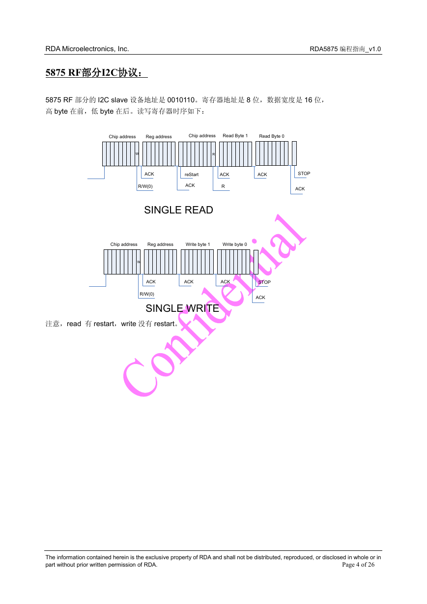
5875 RF 部分的 I2C slave 设备地址是 0010110。寄存器地址是 8 位,数据宽度是 16 位,
高 byte 在前,低 byte 在后。读写寄存器时序如下:
Chip address
Reg address
Chip address
Read Byte 1
Read Byte 0
W
R
ACK
R/W(0)
reStart
ACK
ACK
R
ACK
STOP
ACK
SINGLE READ
Chip address
Reg address
Write byte 1
Write byte 0
W
ACK
R/W(0)
ACK
ACK
STOP
ACK
SINGLE WRITE
注意,read 有 restart,write 没有 restart。
The information contained herein is the exclusive property of RDA and shall not be distributed, reproduced, or disclosed in whole or in
part without prior written permission of RDA.
Page 4 of 26
�
RDA Microelectronics, Inc. RDA5875 编程指南_v1.0
5875 Core部分I2C协议:
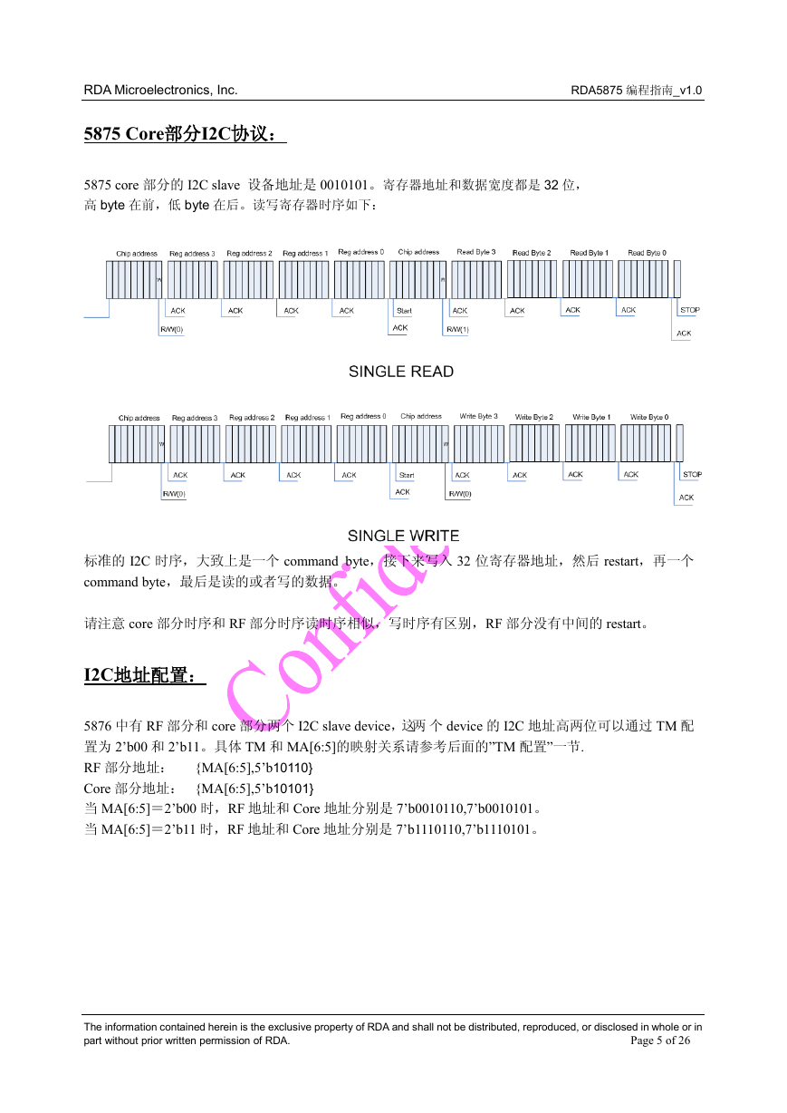
5875 core 部分的 I2C slave 设备地址是 0010101。寄存器地址和数据宽度都是 32 位,
高 byte 在前,低 byte 在后。读写寄存器时序如下:
标准的 I2C 时序,大致上是一个 command byte,接下来写入 32 位寄存器地址,然后 restart,再一个
command byte,最后是读的或者写的数据。
请注意 core 部分时序和 RF 部分时序读时序相似,写时序有区别,RF 部分没有中间的 restart。
I2C地址配置:
5876 中有 RF 部分和 core 部分两个 I2C slave device,这两 个 device 的 I2C 地址高两位可以通过 TM 配
置为 2’b00 和 2’b11。具体 TM 和 MA[6:5]的映射关系请参考后面的”TM 配置”一节.
RF 部分地址:
{MA[6:5],5’b10110}
Core 部分地址: {MA[6:5],5’b10101}
当 MA[6:5]=2’b00 时,RF 地址和 Core 地址分别是 7’b0010110,7’b0010101。
当 MA[6:5]=2’b11 时,RF 地址和 Core 地址分别是 7’b1110110,7’b1110101。
The information contained herein is the exclusive property of RDA and shall not be distributed, reproduced, or disclosed in whole or in
part without prior written permission of RDA.
Page 5 of 26
�
RDA Microelectronics, Inc. RDA5875 编程指南_v1.0
UART波特率配置:
5875 缺省是 115200 波特率,最高支持到 3.2M。
通过 pskey 配置如下:
{0x80000060,0x000e1000}
{0x80000040,0x00000100}
其中,0x80000060 寄存器值为波特率的绝对值,如 0x000e1000 对应的 10 进制就是 921600
0x80000040 为 pskey 使能位,value 的每一个 bit 对应一个 pskey。具体的 pskey 说明请看对应的 pskey
配置
UART 格式:
5875 默认的 UART 格式为 8 位有效数据,一位起始位、一位停止位,没有奇偶校验位。有效数据从最低
位开始传输。
Uart 的格式可以进行修改,修改方式如下:
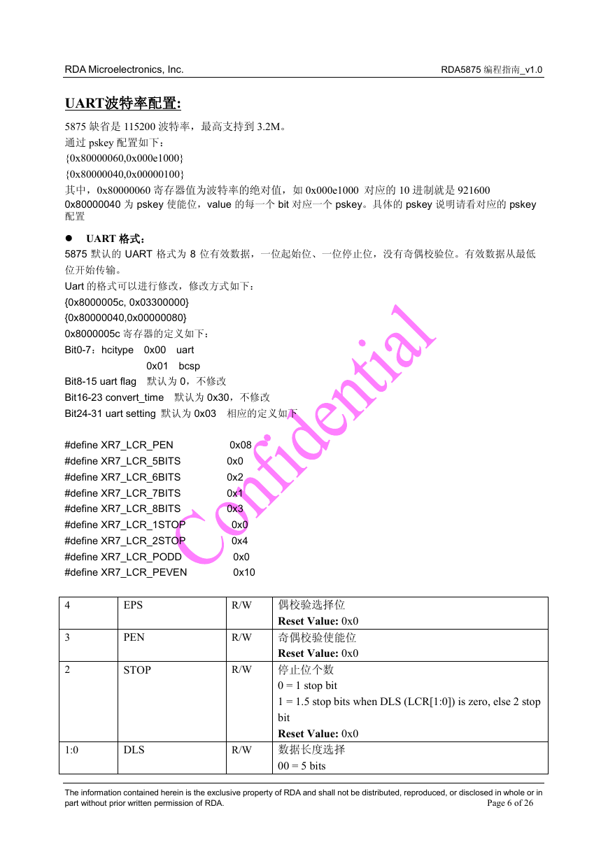
{0x8000005c, 0x03300000}
{0x80000040,0x00000080}
0x8000005c 寄存器的定义如下:
Bit0-7:hcitype 0x00 uart
0x01 bcsp
Bit8-15 uart flag 默认为 0,不修改
Bit16-23 convert_time 默认为 0x30,不修改
Bit24-31 uart setting 默认为 0x03 相应的定义如下
#define XR7_LCR_PEN 0x08
#define XR7_LCR_5BITS 0x0
#define XR7_LCR_6BITS 0x2
#define XR7_LCR_7BITS 0x1
#define XR7_LCR_8BITS 0x3
#define XR7_LCR_1STOP 0x0
#define XR7_LCR_2STOP 0x4
#define XR7_LCR_PODD 0x0
#define XR7_LCR_PEVEN 0x10
4
R/W
EPS
3
2
PEN
STOP
R/W
R/W
1:0
DLS
R/W
偶校验选择位
Reset Value: 0x0
奇偶校验使能位
Reset Value: 0x0
停止位个数
0 = 1 stop bit
1 = 1.5 stop bits when DLS (LCR[1:0]) is zero, else 2 stop
bit
Reset Value: 0x0
数据长度选择
00 = 5 bits
The information contained herein is the exclusive property of RDA and shall not be distributed, reproduced, or disclosed in whole or in
part without prior written permission of RDA.
Page 6 of 26
�
RDA Microelectronics, Inc. RDA5875 编程指南_v1.0
01 = 6 bits
10 = 7 bits
11 = 8 bits
Reset Value: 0x0
UART流控配置:
UART 缺省关闭流控,可以通过配置 UART 寄存器开启流控功能。有的平台有用。
就目前看到的来讲,只要是平台原来有开流控的,我们也必须开。因为流控在进入睡眠时会无效,唤
醒后时钟恢复好后才会重新有效。流控信号同时也有代表时钟是否恢复好的物理意义,参与睡眠握手
机制,所以固定接为有效是不行的。这是合理的,睡眠时当然流控应该无效。5875 也支持睡眠时自动
拉高 RTS,时钟恢复好后才拉低。
5875 有对应的流控脚 rts 和 cts
但是 5876 由于 pin 脚数量限制,没有专门的流控脚,那么如果需要开启流控配置,就需要把 gpio2 作
为流控脚 cts,把 mcu 的 rts 接地,因为蓝牙的 uart 硬件 buff 比较大,所以可以默认以为 bb 任何时候
都可以向蓝牙发数。
如果采用 gpio2 为流控脚的话,需要进行如下配置配置
{0x40200044,0x0000003c};
开启流控的配置是:
{0x50000010,0x00000122};
The information contained herein is the exclusive property of RDA and shall not be distributed, reproduced, or disclosed in whole or in
part without prior written permission of RDA.
Page 7 of 26
�
RDA Microelectronics, Inc. RDA5875 编程指南_v1.0
PCM接口配置:
PCM接口简单说明
PCM 接口用于 RDA5875 与 Host 系统之间传输蓝牙语音数据,通过 PCM 接口,在建立 SCO 连接后
可以发送和接收 PCM 数据。PCM 接口共有 4 根信号,PCM_CLK, PCM_SYNC, PCM_IN 和 PCM_OUT.
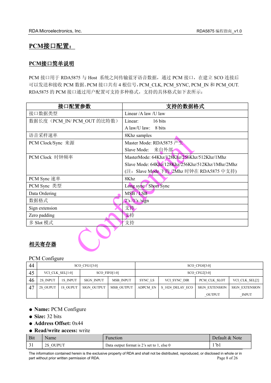
RDA5875 的 PCM 接口通过用户配置可支持多种格式,支持的具体格式如下表所示:
接口配置参数
支持的数据格式
接口数据类型
数据长度(PCM_IN/ PCM_OUT 的比特数) Linear: 16 bits
Linear /A law /U law
A law/U law: 8 bits
8Khz samples
Master Mode: RDA5875 产生
Slave Mode: 来自外部
MasterMode: 64Khz/128Khz/256Khz/512Khz/1Mhz
Slave Mode: 64Khz/128Khz/256Khz/512Khz/1Mhz/2Mhz
(注:Slave Mode 下的 2Mhz 时钟在 RDA5875 中支持)
8Khz
Long sync / Short Sync
MSB / LSB
2’s /1’s /sign
支持
支持
支持
语音采样速率
PCM Clock/Sync 来源
PCM Clock 时钟频率
PCM Sync 速率
PCM Sync 类型
Data Ordering
数据格式
Sign extension
Zero padding
多 Slot 模式
相关寄存器
PCM Configure
44
45
46
47
2S_OUPUT
2S_INPUT
VCI_CLK_SEL[1:0]
SCO_CFG1[3:0]
SCO_FIFO[1:0]
SCO_CFG0[3:0]
SCO_CFG2[3:0]
1S_INPUT
1S_OUPUT
SIGN_INPUT
MSB_INPUT
SYNC_LS
VCI_SYNC_DIR
PCM_CLK_SLOT
VCI_CLK_SEL[2]
SIGN_OUTPUT MSB_OUTPUT ADPCM_EN
S_1024_DELAY_ECO
SIGN_EXTENSION
SIGN_EXTENSION
_OUTPUT
_INPUT
● Name: PCM Configure
● Size: 32 bits
● Address Offset: 0x44
● Read/write access: write
Bit
31
The information contained herein is the exclusive property of RDA and shall not be distributed, reproduced, or disclosed in whole or in
part without prior written permission of RDA.
Function
Data output format is 2’s set to 1, else 0
Default & Note
1’b1
Name
2S_OUPUT
Page 8 of 26
�



 2023年江西萍乡中考道德与法治真题及答案.doc
 2012年重庆南川中考生物真题及答案.doc
 2013年江西师范大学地理学综合及文艺理论基础考研真题.doc
 2020年四川甘孜小升初语文真题及答案I卷.doc
 2020年注册岩土工程师专业基础考试真题及答案.doc
 2023-2024学年福建省厦门市九年级上学期数学月考试题及答案.doc
 2021-2022学年辽宁省沈阳市大东区九年级上学期语文期末试题及答案.doc
 2022-2023学年北京东城区初三第一学期物理期末试卷及答案.doc
 2018上半年江西教师资格初中地理学科知识与教学能力真题及答案.doc
 2012年河北国家公务员申论考试真题及答案-省级.doc
 2020-2021学年江苏省扬州市江都区邵樊片九年级上学期数学第一次质量检测试题及答案.doc
 2022下半年黑龙江教师资格证中学综合素质真题及答案.doc