CST MICROWAVE STUDIO ®
3 D E M F O R H I G H F R E Q U E N C I E S
TUTORIALS
C S T S T U D I O S U I T E ™ 2 0 0 6
�
Copyright
© 1998-2005
CST GmbH–Computer Simulation Technology
All rights reserved.
Information in this document is subject to change
without notice. The software described in this
document is furnished under a license agreement
or non-disclosure agreement. The software may
be used only in accordance with the terms of those
agreements.
No part of this documentation may be reproduced,
stored in a retrieval system, or transmitted in
any form or any means electronic or mechanical,
including photocopying and recording for any
purpose other than the purchaser’s personal use
without the written permission of CST.
Trademarks
CST MICROWAVE STUDIO,CST DESIGN ENVIRONMENT,
CST EM STUDIO, CST PARTICLE STUDIO, CST DESIGN
STUDIO are trademarks or registered trademarks of
CST GmbH.
Other brands and their products are trademarks or
registered trademarks of their respective holders and
should be noted as such.
CST–Computer Simulation Technology
www.cst.com
�
CST MICROWAVE STUDIO®
Tutorials
Rectangular Waveguide Tutorial
Coaxial Structure Tutorial
Planar Device Tutorial
Antenna Tutorial
Resonator Tutorial
Filter Tutorial
10/04/2005
3
31
77
115
165
193
�
�
Rectangular Waveguide Tutorial
Geometric Construction and Solver Settings
Introduction and Model Dimensions
Geometric Construction Steps
Calculation of Fields and S-Parameters
Transient Solver
Transient Solver Results
Accuracy Considerations
Frequency Domain Solver
Frequency Domain Solver Results
Accuracy Considerations
Getting More Information
4
4
5
14
14
15
19
22
25
29
30
�
CST MICROWAVE STUDIO® 2006 – Rectangular Waveguide Tutorial
4
Geometric Construction and Solver Settings
Introduction and Model Dimensions
In this tutorial you will learn how to simulate rectangular waveguide devices. As a typical
example for a rectangular waveguide, you will analyze a well-known and commonly used
high frequency device: the Magic Tee. The acquired knowledge of how to model and
analyze this device can also be applied to other devices containing rectangular
waveguides.
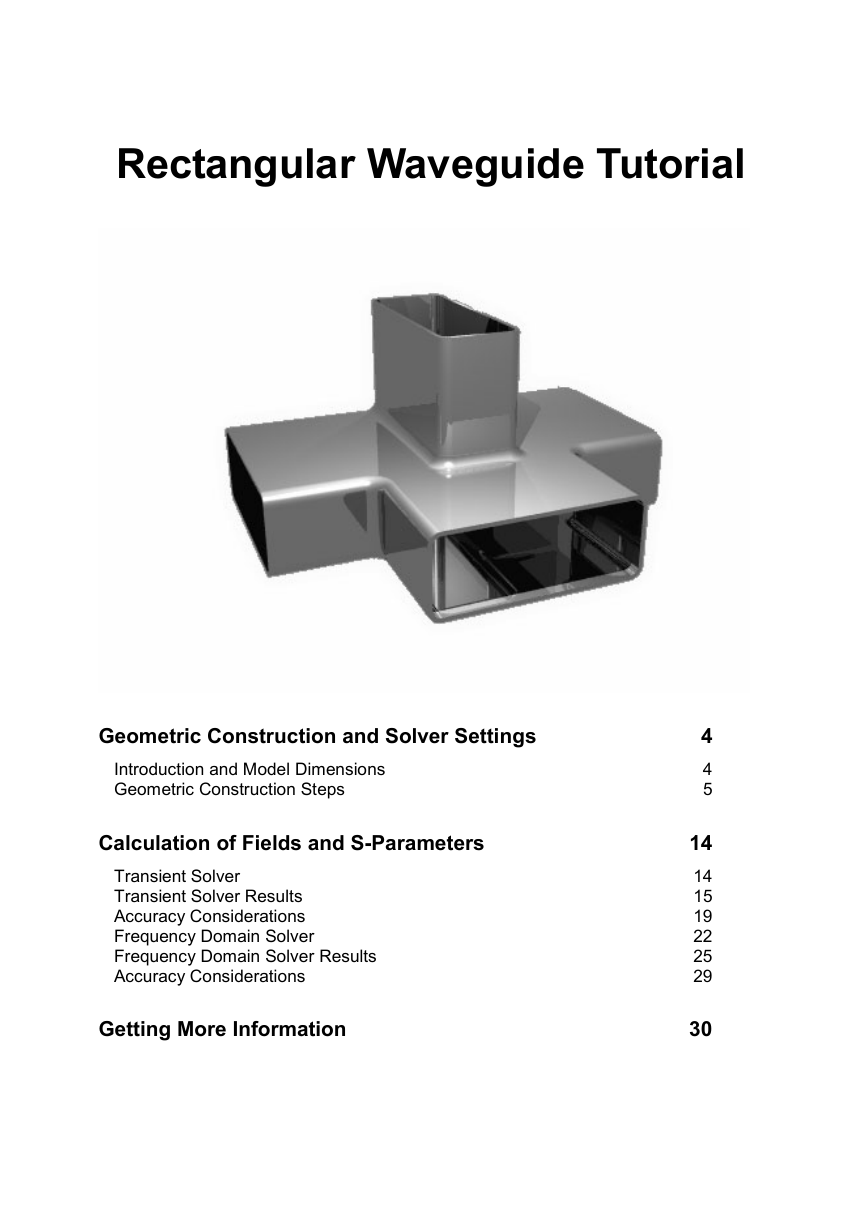
The main idea behind the Magic Tee is to combine a TE and a TM waveguide splitter
(see the figure below for an illustration and the dimensions). Although CST
MICROWAVE STUDIO® can provide a wide variety of results, this tutorial concentrates
solely on the S-parameters and electric fields. In this particular case, port 1 and port 4
are de-coupled, so one can expect S14 and S41 to be very small.
We strongly suggest that you carefully read through the CST MICROWAVE STUDIO®
Getting Started manual before starting this tutorial.
�
CST MICROWAVE STUDIO® 2006 – Rectangular Waveguide Tutorial
5
Geometric Construction Steps
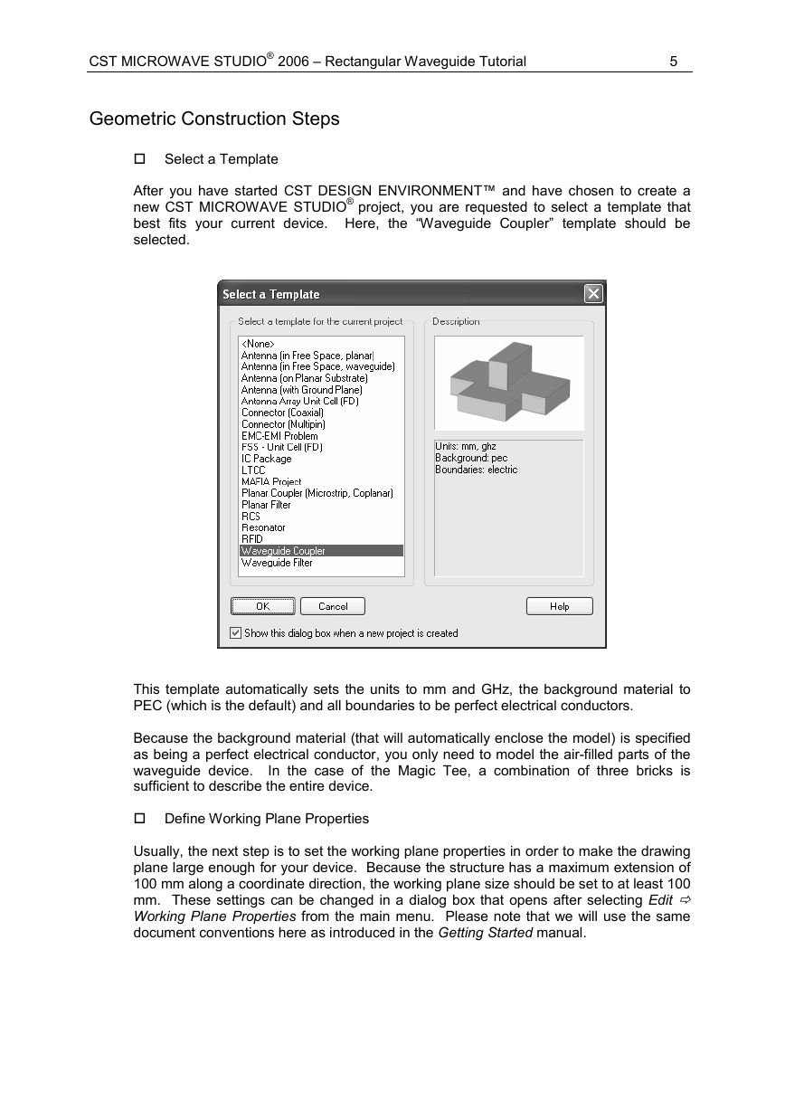
Select a Template
After you have started CST DESIGN ENVIRONMENT™ and have chosen to create a
new CST MICROWAVE STUDIO® project, you are requested to select a template that
best fits your current device. Here, the “Waveguide Coupler” template should be
selected.
This template automatically sets the units to mm and GHz, the background material to
PEC (which is the default) and all boundaries to be perfect electrical conductors.
Because the background material (that will automatically enclose the model) is specified
as being a perfect electrical conductor, you only need to model the air-filled parts of the
waveguide device. In the case of the Magic Tee, a combination of three bricks is
sufficient to describe the entire device.
Define Working Plane Properties
Usually, the next step is to set the working plane properties in order to make the drawing
plane large enough for your device. Because the structure has a maximum extension of
100 mm along a coordinate direction, the working plane size should be set to at least 100
mm. These settings can be changed in a dialog box that opens after selecting Edit
Working Plane Properties from the main menu. Please note that we will use the same
document conventions here as introduced in the Getting Started manual.
�
6
CST MICROWAVE STUDIO® 2006 – Rectangular Waveguide Tutorial
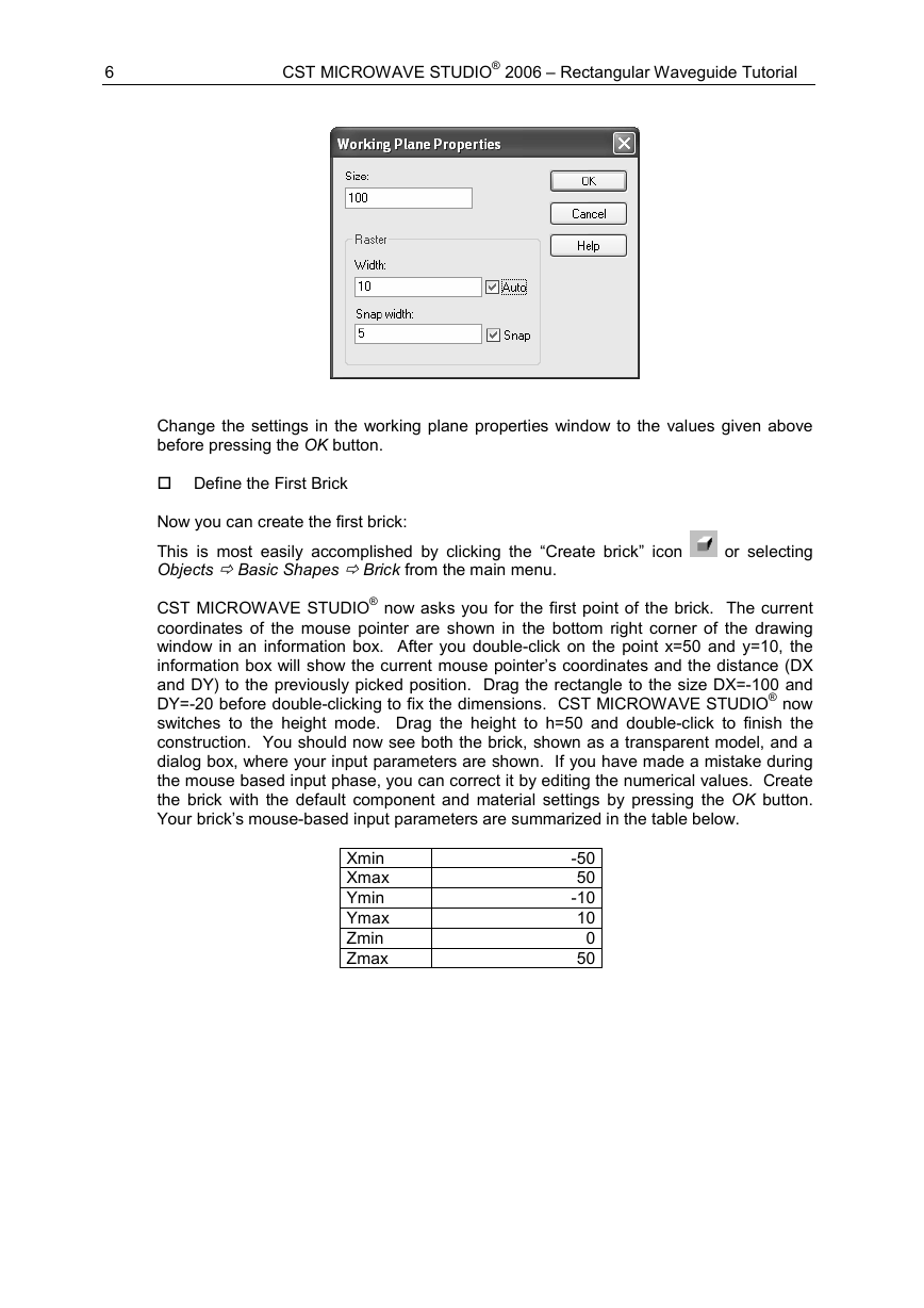
Change the settings in the working plane properties window to the values given above
before pressing the OK button.
Define the First Brick
or selecting
Now you can create the first brick:
This is most easily accomplished by clicking the “Create brick” icon
Objects Basic Shapes Brick from the main menu.
CST MICROWAVE STUDIO® now asks you for the first point of the brick. The current
coordinates of the mouse pointer are shown in the bottom right corner of the drawing
window in an information box. After you double-click on the point x=50 and y=10, the
information box will show the current mouse pointer’s coordinates and the distance (DX
and DY) to the previously picked position. Drag the rectangle to the size DX=-100 and
DY=-20 before double-clicking to fix the dimensions. CST MICROWAVE STUDIO® now
switches to the height mode. Drag the height to h=50 and double-click to finish the
construction. You should now see both the brick, shown as a transparent model, and a
dialog box, where your input parameters are shown. If you have made a mistake during
the mouse based input phase, you can correct it by editing the numerical values. Create
the brick with the default component and material settings by pressing the OK button.
Your brick’s mouse-based input parameters are summarized in the table below.
Xmin
Xmax
Ymin
Ymax
Zmin
Zmax
-50
50
-10
10
0
50
�





 2023年江西萍乡中考道德与法治真题及答案.doc
 2012年重庆南川中考生物真题及答案.doc
 2013年江西师范大学地理学综合及文艺理论基础考研真题.doc
 2020年四川甘孜小升初语文真题及答案I卷.doc
 2020年注册岩土工程师专业基础考试真题及答案.doc
 2023-2024学年福建省厦门市九年级上学期数学月考试题及答案.doc
 2021-2022学年辽宁省沈阳市大东区九年级上学期语文期末试题及答案.doc
 2022-2023学年北京东城区初三第一学期物理期末试卷及答案.doc
 2018上半年江西教师资格初中地理学科知识与教学能力真题及答案.doc
 2012年河北国家公务员申论考试真题及答案-省级.doc
 2020-2021学年江苏省扬州市江都区邵樊片九年级上学期数学第一次质量检测试题及答案.doc
 2022下半年黑龙江教师资格证中学综合素质真题及答案.doc