Contents
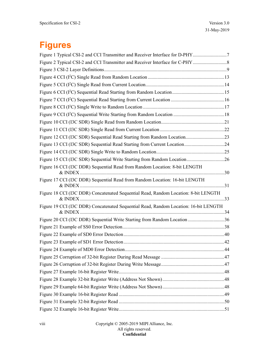
Figures
Tables
Release History
1 Introduction
1.1 Scope
1.2 Purpose
2 Terminology
2.1 Use of Special Terms
2.2 Definitions
2.3 Abbreviations
2.4 Acronyms
3 References
4 Overview of CSI-2
5 CSI-2 Layer Definitions
6 Camera Control Interface (CCI)
6.1 CCI (I2C) Data Transfer Protocol
6.1.1 CCI (I2C) Message Type
6.1.2 CCI (I2C) Read/Write Operations
6.2 CCI (I3C) Data Transfer Protocol
6.2.1 CCI (I3C SDR) Data Transfer Protocol
6.2.1.1 CCI (I3C SDR) Message Type
6.2.1.2 CCI (I3C SDR) Read/Write Operations
6.2.2 CCI (I3C DDR) Data Transfer Protocol
6.2.2.1 CCI (I3C DDR) Message Type
6.2.2.2 CCI (I3C DDR) Read/Write Operations
6.3 CCI (I3C) Error Detection and Recovery
6.3.1 CCI (I3C SDR) Error Detection and Recovery Method
6.3.2 CCI (I3C DDR) Error Detection and Recovery Method
6.3.3 Error Detection and Recovery for CCI (I3C) Master Devices
6.4 CCI (I2C) Slave Addresses
6.5 CCI (I3C) Slave Addresses
6.6 CCI Multi-Byte Registers
6.6.1 Overview
6.6.2 Transmission Byte Order for Multi-Byte Register Values
6.6.3 Multi-Byte Register Protocol (Informative)
6.7 CCI I/O Electrical and Timing Specifications
7 Physical Layer
7.1 D-PHY Physical Layer Option
7.2 C-PHY Physical Layer Option
7.3 PHY Support for the CSI-2 Unified Serial Link (USL) Feature
7.3.1 D-PHY Support Requirements for USL Feature
7.3.2 C-PHY Support Requirements for USL Feature
8 Multi-Lane Distribution and Merging
8.1 Lane Distribution for the D-PHY Physical Layer Option
8.2 Lane Distribution for the C-PHY Physical Layer Option
8.3 Multi-Lane Interoperability
8.3.1 C-PHY Lane De-Skew
9 Low Level Protocol
9.1 Low Level Protocol Packet Format
9.1.1 Low Level Protocol Long Packet Format
9.1.2 Low Level Protocol Short Packet Format
9.2 Data Identifier (DI)
9.3 Virtual Channel Identifier
9.4 Data Type (DT)
9.5 Packet Header Error Correction Code for D-PHY Physical LayerOption
9.5.1 General Hamming Code Applied to Packet Header
9.5.2 Hamming-Modified Code
9.5.3 ECC Generation on TX Side
9.5.4 Applying ECC on RX Side (Informative)
9.6 Checksum Generation
9.7 Packet Spacing
9.8 Synchronization Short Packet Data Type Codes
9.8.1 Frame Synchronization Packets
9.8.2 Line Synchronization Packets
9.9 Generic Short Packet Data Type Codes
9.10 Packet Spacing Examples Using the Low Power State
9.11 Latency Reduction and Transport Efficiency (LRTE)
9.11.1 Interpacket Latency Reduction (ILR)
9.11.2 Using ILR and Enhanced Transport Efficiency Together
9.11.3 LRTE Register Tables
9.12 Unified Serial Link (USL)
9.12.1 USL Technical Overview
9.12.2 USL Command Payload Constructs
9.12.3 USL Operation Procedures
9.12.4 Monitoring USL Command Transport Integrity
9.12.5 USL Powerup / Reset, SNS Configuration, and Mode Switching
9.13 Data Scrambling
9.13.1 CSI-2 Scrambling for D-PHY
9.13.2 CSI-2 Scrambling for C-PHY
9.13.3 Scrambling Details
9.14 Smart Region of Interest (SROI)
9.14.1 Overview of SROI Frame Format
9.14.2 Transmission of SROI Embedded Data Packet
9.14.3 SROI Packet Detection Options
9.14.4 SROI Use Cases (Informative)
9.14.5 Format of SROI Embedded Data Packet (SEDP)
9.15 Packet Data Payload Size Rules
9.16 Frame Format Examples
9.17 Data Interleaving
9.17.1 Data Type Interleaving
9.17.2 Virtual Channel Identifier Interleaving
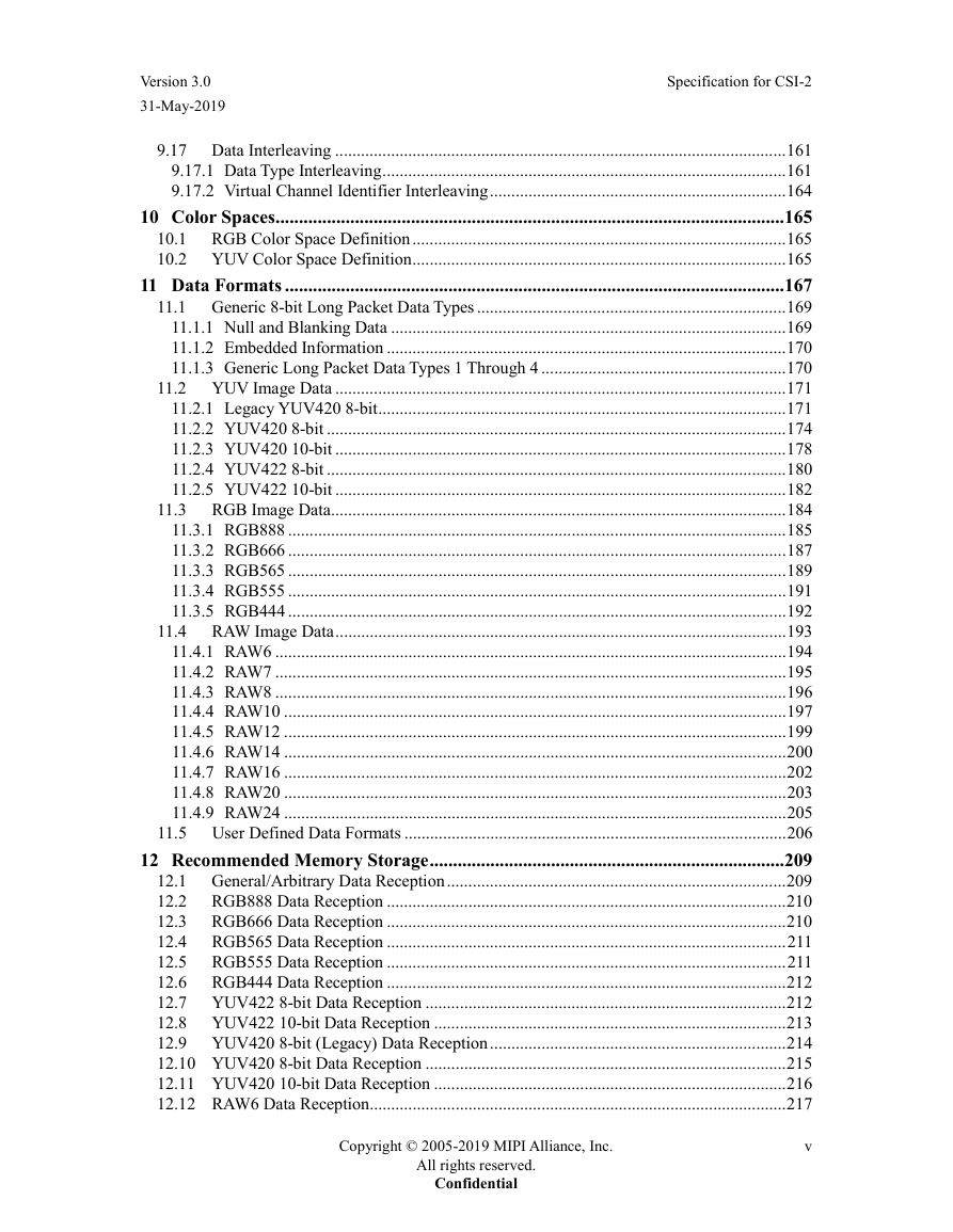
10 Color Spaces
10.1 RGB Color Space Definition
10.2 YUV Color Space Definition
11 Data Formats
11.1 Generic 8-bit Long Packet Data Types
11.1.1 Null and Blanking Data
11.1.2 Embedded Information
11.1.3 Generic Long Packet Data Types 1 Through 4
11.2 YUV Image Data
11.2.1 Legacy YUV420 8-bit
11.2.2 YUV420 8-bit
11.2.3 YUV420 10-bit
11.2.4 YUV422 8-bit
11.2.5 YUV422 10-bit
11.3 RGB Image Data
11.3.1 RGB888
11.3.2 RGB666
11.3.3 RGB565
11.3.4 RGB555
11.3.5 RGB444
11.4 RAW Image Data
11.4.1 RAW6
11.4.2 RAW7
11.4.3 RAW8
11.4.4 RAW10
11.4.5 RAW12
11.4.6 RAW14
11.4.7 RAW16
11.4.8 RAW20
11.4.9 RAW24
11.5 User Defined Data Formats
12 Recommended Memory Storage
12.1 General/Arbitrary Data Reception
12.2 RGB888 Data Reception
12.3 RGB666 Data Reception
12.4 RGB565 Data Reception
12.5 RGB555 Data Reception
12.6 RGB444 Data Reception
12.7 YUV422 8-bit Data Reception
12.8 YUV422 10-bit Data Reception
12.9 YUV420 8-bit (Legacy) Data Reception
12.10 YUV420 8-bit Data Reception
12.11 YUV420 10-bit Data Reception
12.12 RAW6 Data Reception
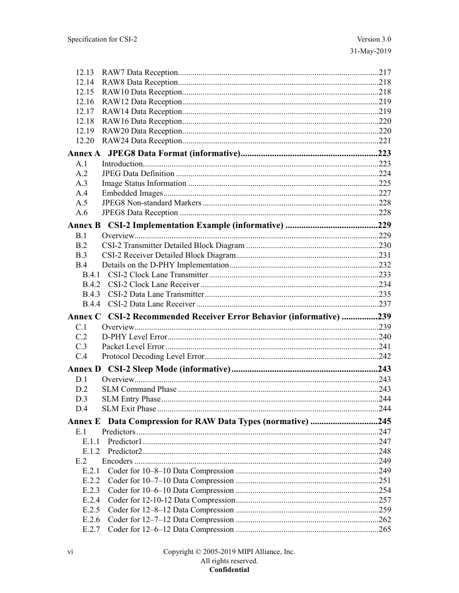
12.13 RAW7 Data Reception
12.14 RAW8 Data Reception
12.15 RAW10 Data Reception
12.16 RAW12 Data Reception
12.17 RAW14 Data Reception
12.18 RAW16 Data Reception
12.19 RAW20 Data Reception
12.20 RAW24 Data Reception
Annex A JPEG8 Data Format (informative)
A.1 Introduction
A.2 JPEG Data Definition
A.3 Image Status Information
A.4 Embedded Images
A.5 JPEG8 Non-standard Markers
A.6 JPEG8 Data Reception
Annex B CSI-2 Implementation Example (informative)
B.1 Overview
B.2 CSI-2 Transmitter Detailed Block Diagram
B.3 CSI-2 Receiver Detailed Block Diagram
B.4 Details on the DPHY Implementation
B.4.1 CSI-2 Clock Lane Transmitter
B.4.2 CSI-2 Clock Lane Receiver
B.4.3 CSI-2 Data Lane Transmitter
B.4.4 CSI-2 Data Lane Receiver
Annex C CSI-2 Recommended Receiver Error Behavior (informative)
C.1 Overview
C.2 D-PHY Level Error
C.3 Packet Level Error
C.4 Protocol Decoding Level Error
Annex D CSI-2 Sleep Mode (informative)
D.1 Overview
D.2 SLM Command Phase
D.3 SLM Entry Phase
D.4 SLM Exit Phase
Annex E Data Compression for RAW Data Types (normative)
E.1 Predictors
E.1.1 Predictor1
E.1.2 Predictor2
E.2 Encoders
E.2.1 Coder for 10–8–10 Data Compression
E.2.2 Coder for 10–7–10 Data Compression
E.2.3 Coder for 10–6–10 Data Compression
E.2.4 Coder for 12-10-12 Data Compression
E.2.5 Coder for 12–8–12 Data Compression
E.2.6 Coder for 12–7–12 Data Compression
E.2.7 Coder for 12–6–12 Data Compression
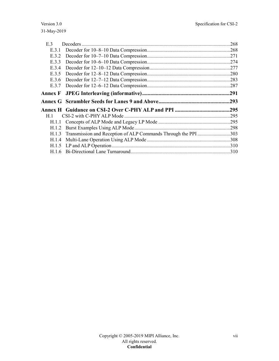
E.3 Decoders
E.3.1 Decoder for 10–8–10 Data Compression
E.3.2 Decoder for 10–7–10 Data Compression
E.3.3 Decoder for 10–6–10 Data Compression
E.3.4 Decoder for 12–10–12 Data Compression
E.3.5 Decoder for 12–8–12 Data Compression
E.3.6 Decoder for 12–7–12 Data Compression
E.3.7 Decoder for 12–6–12 Data Compression
Annex F JPEG Interleaving (informative)
Annex G Scrambler Seeds for Lanes 9 and Above
Annex H Guidance on CSI-2 Over C-PHY ALP and PPI
H.1 CSI-2 with C-PHY ALP Mode
H.1.1 Concepts of ALP Mode and Legacy LP Mode
H.1.2 Burst Examples Using ALP Mode
H.1.3 Transmission and Reception of ALP Commands Through the PPI
H.1.4 Multi-Lane Operation Using ALP Mode
H.1.5 LP and ALP Operation
H.1.6 Bi-Directional Lane Turnaround


 2023年江西萍乡中考道德与法治真题及答案.doc
 2012年重庆南川中考生物真题及答案.doc
 2013年江西师范大学地理学综合及文艺理论基础考研真题.doc
 2020年四川甘孜小升初语文真题及答案I卷.doc
 2020年注册岩土工程师专业基础考试真题及答案.doc
 2023-2024学年福建省厦门市九年级上学期数学月考试题及答案.doc
 2021-2022学年辽宁省沈阳市大东区九年级上学期语文期末试题及答案.doc
 2022-2023学年北京东城区初三第一学期物理期末试卷及答案.doc
 2018上半年江西教师资格初中地理学科知识与教学能力真题及答案.doc
 2012年河北国家公务员申论考试真题及答案-省级.doc
 2020-2021学年江苏省扬州市江都区邵樊片九年级上学期数学第一次质量检测试题及答案.doc
 2022下半年黑龙江教师资格证中学综合素质真题及答案.doc