Short introduction to OFDM
Mérouane Debbah
Abstract
0-1
We provide hereafter some notions on OFDM wireless transmissions. Any comments should be sent to: Mérouane
Debbah, Alcatel-Lucent Chair on Flexible Radio, Supelec, 3 rue Joliot-Curie 91192 GIF SUR YVETTE CEDEX, France,
merouane.debbah@supelec.fr.
I. INTRODUCTION
Recently, a worldwide convergence has occurred for the use of Orthogonal Frequency Division Multiplex-
ing (OFDM) as an emerging technology for high data rates. In particular, many wireless standards (Wi-Max,
IEEE802.11a, LTE, DVB) have adopted the OFDM technology as a mean to increase dramatically future wireless
communications. OFDM is a particular form of Multi-carrier transmission and is suited for frequency selective
channels and high data rates. This technique transforms a frequency-selective wide-band channel into a group of
non-selective narrowband channels, which makes it robust against large delay spreads by preserving orthogonality
in the frequency domain. Moreover, the ingenious introduction of cyclic redundancy at the transmitter reduces the
complexity to only FFT processing and one tap scalar equalization at the receiver1
.
II. OFDM PRINCIPLE
In this section, we will focus on the baseband discrete-time representation of OFDM. For a more general pre-
sentation based on orthogonal transmultiplexers or block precoding issues, the reader can refer to [?], [1], [2].
The history of multi-carrier modulation began more then 30 years ago. At the beginning, only analog design based
on the use of orthogonal waveforms was proposed [3]. The use of discrete Fourier Transform (DFT) for modula-
tion and demodulation was first proposed in [4]. Only recently has it been finding its way into commercial use, as
the recent developments in technology have lowered the cost of the signal processing that is needed to implement
OFDM systems [5], [6], [7].
In this section, we first give a brief overview of frequency selective channels [8], [9]
Let r(t) be the low-pass received signal:
r(t) =
∞
−∞
c(τ)x(t − τ)dτ + n(t).
(1)
Frequency selectivity occurs whenever the transmitted signal x(t) occupies an interval bandwidth [− W
2 ] greater
then the coherence bandwidth Bcoh of the channel c(t) (defined as the inverse of the delay spread Td [8]). In this
case, the frequency components of x(t) with frequency separation exceeding Bcoh are subject to different gains.
2 , W
The multipath-channel can be modeled by an impulse response given by c(t) =
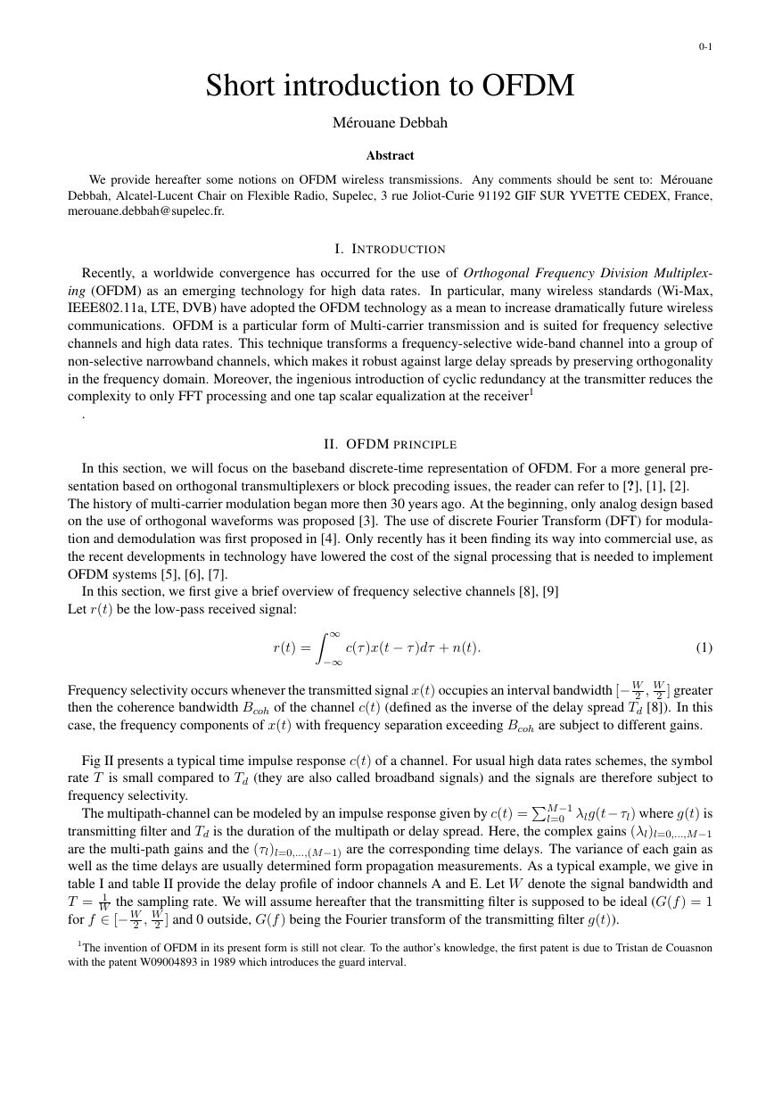
Fig II presents a typical time impulse response c(t) of a channel. For usual high data rates schemes, the symbol
rate T is small compared to Td (they are also called broadband signals) and the signals are therefore subject to
frequency selectivity.
l=0 λlg(t− τl) where g(t) is
transmitting filter and Td is the duration of the multipath or delay spread. Here, the complex gains (λl)l=0,...,M−1
are the multi-path gains and the (τl)l=0,...,(M−1) are the corresponding time delays. The variance of each gain as
well as the time delays are usually determined form propagation measurements. As a typical example, we give in
table I and table II provide the delay profile of indoor channels A and E. Let W denote the signal bandwidth and
T = 1
W the sampling rate. We will assume hereafter that the transmitting filter is supposed to be ideal (G(f) = 1
for f ∈ [− W
M−1
2 , W
2 ] and 0 outside, G(f) being the Fourier transform of the transmitting filter g(t)).
1The invention of OFDM in its present form is still not clear. To the author’s knowledge, the first patent is due to Tristan de Couasnon
with the patent W09004893 in 1989 which introduces the guard interval.
�
Tap Number Delay (ns) Average Relative Power (dB)
0-2
1
2
3
4
5
6
7
8
9
10
11
12
13
14
15
16
17
18
0
10
20
30
40
50
60
70
80
90
110
140
170
200
240
290
340
390
0
-0.9
-1.7
-2.6
-3.5
-4.3
-5.2
-6.1
-6.9
-7.8
-4.7
-7.3
-9.9
-12.5
-13.7
-18.0
-22.4
-26.7
MODEL A, CORRESPONDING TO A TYPICAL OFFICE ENVIRONMENT FOR NLOS CONDITIONS.
TABLE I
Tap Number Delay (ns) Average Relative Power (dB)
1
2
3
4
5
6
7
8
9
10
11
12
13
14
15
16
17
18
0
10
20
40
70
100
140
190
240
320
430
560
710
880
1070
1280
1510
1760
-4.9
-5.1
-5.2
-0.8
-1.3
-1.9
-0.3
-1.2
-2.1
-0.0
-1.9
-2.8
-5.4
-7.3
-10.6
-13.4
-17.4
-20.9
MODEL E, CORRESPONDING TO A TYPICAL LARGE OPEN SPACE ENVIRONMENT FOR NLOS CONDITIONS.
TABLE II
�
0-3
Fig. 1. Multi-path channel.
One of the main concerns in transmissions schemes is to retrieve x(t) from eq (1). This operation is called
equalization and the difficulty of extracting x(t) is mostly due to the frequency selectivity behavior of the channel
(with c(t) = δ(t) where δ(t) is the Dirac distribution, no equalization is required!). Moreover, the equalization
task is all the more difficult to implement that the complexity of an equalizer grows with the channel memory.
Therefore, the cost (in terms of complexity and power consumption) of such an equalizer could be prohibitively
too high, especially in the case of high data rates communications. The main idea of OFDM transmissions is to
turn the channel convolutional effect of equation (1) into a multiplicative one in order to simplify the equalization
task. To this end, OFDM schemes add redundancy known as cyclic prefix in a clever manner in order to circularize
the channel effect. Based on the fact that circular convolution can be diagonalized in an FFT basis [10], the multi-
path time domain channel is transformed into a set of parallel frequency flat fading channels. Moreover, OFDM
systems take benefit from the low cost implementation structure of digital FFT modulators2. All these advantages
make OFDM particularly suited for frequency selective channels.
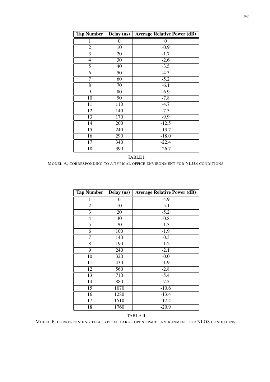
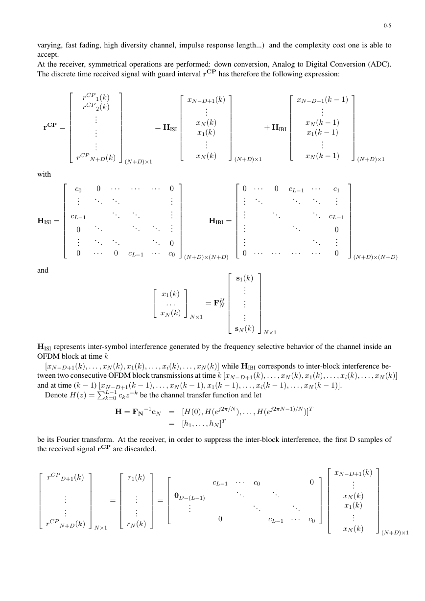
Fig. 2. OFDM model.
Let us now focus on the conventional OFDM transceiver depicted in fig.II. As a starting point, we will con-
sider the noiseless transmission case. The incoming high rate information is split onto N rate sub-carriers .
The data is therefore transmitted by blocks of size N: s(k) = [s1(k), . . . , si(k), . . . , sN (k)] where the index
k is the block OFDM symbol number and the subscript i is for the carrier index. The block OFDM symbol
2The reader should note that other schemes based on block redundant precoding are also able to circularize the linear convolution (zero-
padded OFDM [11], pseudo-random cyclic prefix [?])
.T�0jc���jTd.bnsamplingrateTDACP=SMODULATORmodulationDEMODULATORparallelconversiontoserialguardintervalinsertiondigitaltoconverterdemodulationsamplingrateTP=SrnADCr�t�serialtoparallelconversionanalogtodigitalconverterguardintervalsuppressionanalogs1�k�s2�k�sN�k�s�k�x�k�x1�k�x2�k�x3�k�xN�k�xN�D�1�k�xN�D�1�k�xN�k�x1�k�xN�k�C�t�xnx�t�rcp1�k�rcpD�k�r1�k�r2�k�r3�k�rN�k�rcp�k�y�k�y1�k�yN�k�h�1h�Nr�k�rcpN�D�k�FF�1�
N = F−1
N to yield the so-called time domain block vector x(k) =
is precoded by an inverse FFT matrix FH
[x1(k), . . . , xi(k), . . . , xN (k)]. At the output of the IFFT, a guard interval of D samples is inserted at the be-
ginning of each block [xN−D+1(k), . . . , xN (k), x1(k), . . . , xi(k), . . . , xN (k)]. It consists of a cyclic extension of
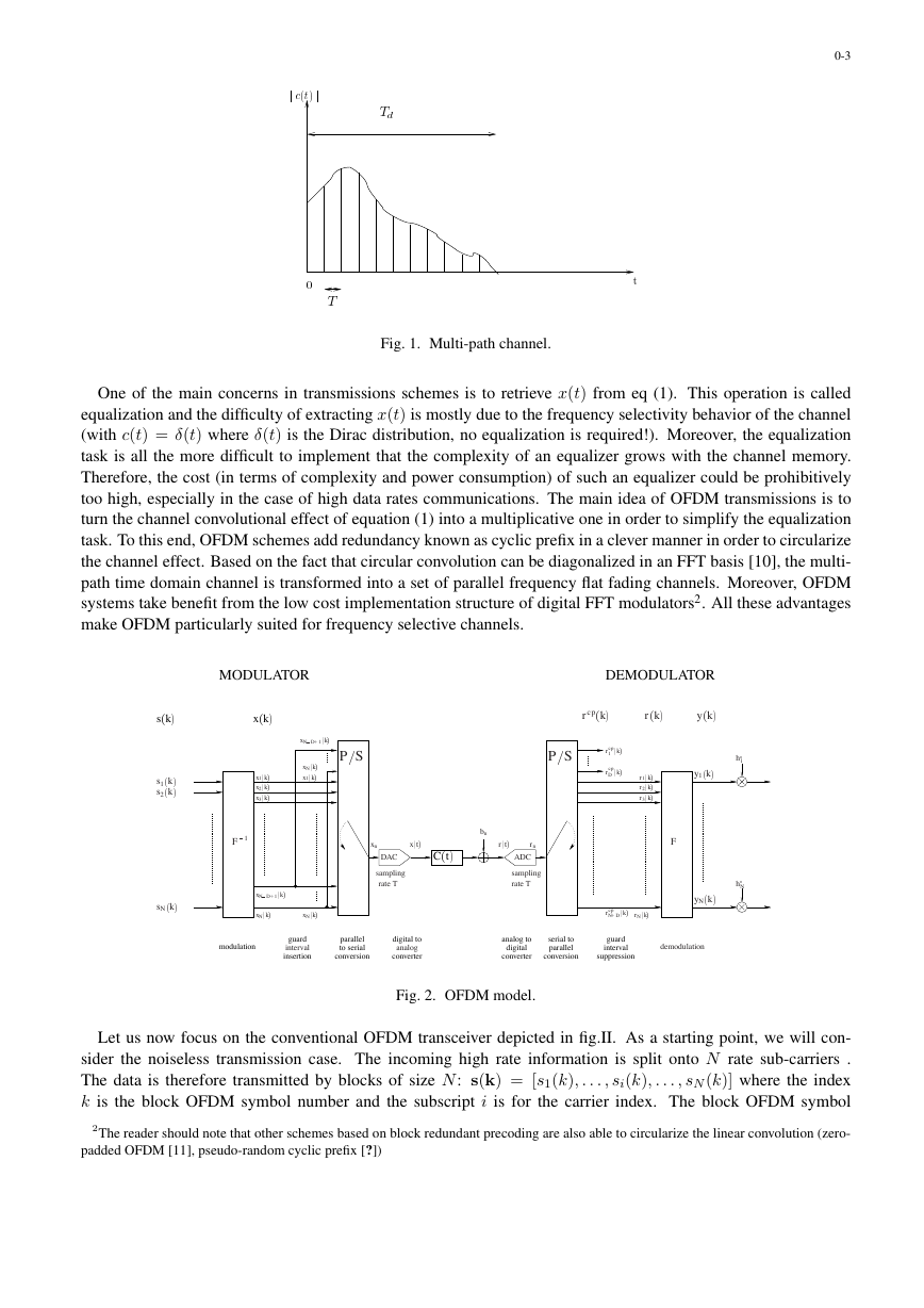
the time domain OFDM symbol of size larger than the channel impulse response (D > L − 1). The cyclic prefix
(CP) is appended between each block in order to transform the multipath linear convolution into a circular one. Af-
ter Parallel to Serial (P/S) and Digital to Analog Conversion (ADC), the signal is sent through a frequency-selective
channel.
0-4
Fig. 3.
time representation of OFDM.
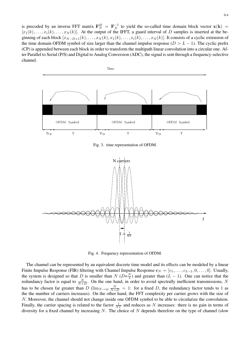
Fig. 4. Frequency representation of OFDM.
The channel can be represented by an equivalent discrete time model and its effects can be modeled by a linear
Finite Impulse Response (FIR) filtering with Channel Impulse Response cN = [c1, . . . , cL−1, 0, . . . , 0]. Usually,
4 ) and greater than (L − 1). One can notice that the
the system is designed so that D is smaller than N (D= N
N +D . On the one hand, in order to avoid spectrally inefficient transmissions, N
redundancy factor is equal to N
has to be chosen far greater than D (limN→∞ N
N +D = 1: for a fixed D, the redundancy factor tends to 1 as
the the number of carriers increases). On the other hand, the FFT complexity per carrier grows with the size of
N. Moreover, the channel should not change inside one OFDM symbol to be able to circularize the convolution.
Finally, the carrier spacing is related to the factor
N T and reduces as N increases: there is no gain in terms of
diversity for a fixed channel by increasing N. The choice of N depends therefore on the type of channel (slow
1
.TTTTc�Tc�Tc�Ti�e�FD��FD��FD�Sy�b��Sy�b��Sy�b��.fNcarriersDf=1NT�
0-5
varying, fast fading, high diversity channel, impulse response length...) and the complexity cost one is able to
accept.
At the receiver, symmetrical operations are performed: down conversion, Analog to Digital Conversion (ADC).
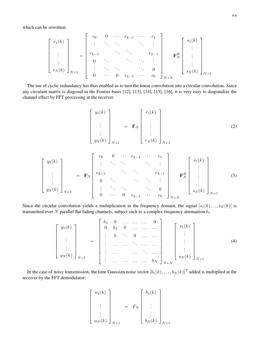
The discrete time received signal with guard interval rCP has therefore the following expression:
rCP
rCP
1(k)
2(k)
...
...
...
N +D(k)
rCP
xN−D+1(k)
...
xN (k)
x1(k)
...
xN (k)
= HISI
(N +D)×1
xN−D+1(k − 1)
...
...
xN (k − 1)
x1(k − 1)
xN (k − 1)
+ HIBI
(N +D)×1
(N +D)×1
c0
...
cL−1
0
...
0
0
...
...
...
···
···
...
...
...
0
···
···
...
...
cL−1
...
...
···
0
...
...
...
0
c0
HIBI =
0 ···
...
...
...
...
...
0 ···
0
...
···
cL−1
...
...
···
···
...
...
...
···
c1
...
cL−1
0
...
0
(N +D)×(N +D)
rCP =
with
HISI =
and
(N +D)×(N +D)
x1(k)
. . .
xN (k)
N×1
= FH
N
s1(k)
...
...
...
HISI represents inter-symbol interference generated by the frequency selective behavior of the channel inside an
OFDM block at time k
sN (k)
N×1
[xN−D+1(k), . . . , xN (k), x1(k), . . . , xi(k), . . . , xN (k)] while HIBI corresponds to inter-block interference be-
tween two consecutive OFDM block transmissions at time k [xN−D+1(k), . . . , xN (k), x1(k), . . . , xi(k), . . . , xN (k)]
and at time (k − 1) [xN−D+1(k − 1), . . . , xN (k − 1), x1(k − 1), . . . , xi(k − 1), . . . , xN (k − 1)].
Denote H(z) =
k=0 ckz−k be the channel transfer function and let
L−1
H = FN
−1cN = [H(0), H(ej2π/N ), . . . , H(ej2πN−1)/N )]T
= [h1, . . . , hN ]T
be its Fourier transform. At the receiver, in order to suppress the inter-block interference, the first D samples of
the received signal rCP are discarded.
rCP
D+1(k)
...
...
N +D(k)
=
r1(k)
...
...
=
rCP
N×1
rN (k)
0D−(L−1)
...
cL−1
···
...
0
c0
...
...
cL−1
...
···
0
c0
xN−D+1(k)
...
xN (k)
x1(k)
...
xN (k)
(N +D)×1
�
which can be rewritten:
r1(k)
...
...
rN (k)
N×1
=
c0
...
cL−1
0
...
0
0
...
...
...
···
···
...
...
...
0
cL−1
...
...
cL−1
···
...
...
...
···
c1
...
cL−1
...
0
c0
0-6
s1(k)
...
...
...
FH
N
sN (k)
N×1
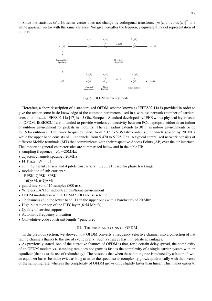
The use of cyclic redundancy has thus enabled us to turn the linear convolution into a circular convolution. Since
any circulant matrix is diagonal in the Fourier basis [12], [13], [14], [15], [16], it is very easy to diagonalize the
channel effect by FFT processing at the receiver:
y1(k)
...
...
yN (k)
N×1
r1(k)
...
...
rN (k)
= FN
y1(k)
...
...
yN (k)
N×1
= FN
c0
...
cL−1
0
...
0
0
...
...
...
···
···
...
...
...
0
cL−1
...
...
cL−1
···
...
...
...
···
c1
...
cL−1
...
0
c0
(2)
(3)
s1(k)
...
...
...
FH
N
sN (k)
N×1
Since the circular convolution yields a multiplication in the frequency domain, the signal [s1(k), ..., sN (k)] is
transmitted over N parallel flat fading channels, subject each to a complex frequency attenuation hi
y1(k)
...
...
yN (k)
N×1
h1
0
...
...
...
...
0
h2
0
. . .
. . .
. . .
. . .
0
...
. . .
. . .
. . .
. . .
0
...
. . .
. . .
. . .
. . .
. . .
0
. . .
. . .
. . .
. . .
...
. . . hN
. . .
N×N
s1(k)
...
...
...
sN (k)
N×1
N×N
(4)
In the case of noisy transmission, the time Gaussian noise vector [b1(k), . . . , bN (k)]T added is multiplied at the
receiver by the FFT demodulator:
n1(k)
...
...
b1(k)
...
...
= FN
nN (k)
N×1
bN (k)
N×1
=
N×N
N×1
�
Since the statistics of a Gaussian vector does not change by orthogonal transform, [n1(k), . . . , nN (k)]T is a
white gaussian vector with the same variance. We give hereafter the frequency equivalent model representation of
OFDM.
0-7
Fig. 5. OFDM frequency model.
Hereafter, a short description of a standardized OFDM scheme known as IEEE802.11a is provided in order to
give the reader some basic knowledge of the common parameters used in a wireless network (number of carriers,
constellations,...). IEEE802.11a [17] is a 5 Ghz European Standard developed by IEEE with a physical layer based
on OFDM. IEEE802.11a is intended to provide wireless connectivity between PCs, laptops. . . either in an indoor
or outdoor environment for pedestrian mobility. The cell radius extends to 30 m in indoor environments or up
to 150m outdoors. The lower frequency band, from 5.15 to 5.35 Ghz contains 8 channels spaced by 20 MHz
while the upper band consists of 11 channels, from 5.470 to 5.725 Ghz. A typical centralized network consists of
different Mobile terminals (MT) that communicate with their respective Access Points (AP) over the air interface.
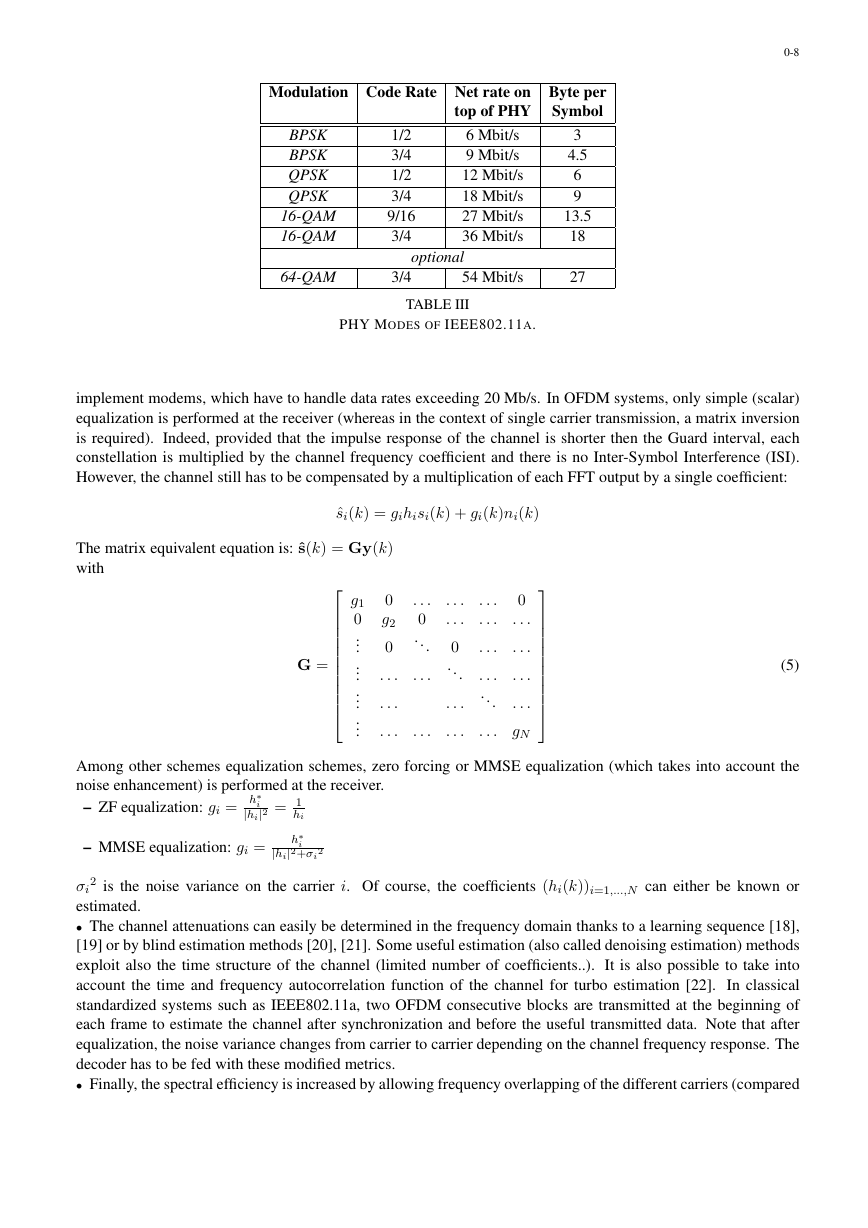
The important general characteristics are summarized below and in the table III:
• sampling frequency : Fe =20MHz;
• adjacent channels spacing : 20MHz;
• FFT size : N = 64;
• K = 48 useful carriers and 4 pilots (on carriers : ±7, ±21; used for phase tracking);
• modulation of sub-carriers :
– BPSK, QPSK, 8PSK,
– 16QAM, 64QAM;
• guard interval of 16 samples (800 ns).
• Wireless LAN for indoor/campus/home environment
• OFDM modulation with a TDMA/TDD access scheme
• 19 channels (8 in the lower band, 11 in the upper one) with a bandwidth of 20 Mhz
• High bit rate on top of the PHY layer (6-54 Mbit/s)
• Quality of service support
• Automatic frequency allocation
• Convolutive code constraint length 7 punctured
III. THE PROS AND CONS OF OFDM
In the previous section, we showed how OFDM converts a frequency selective channel into a collection of flat
fading channels thanks to the use of cyclic prefix. Such a strategy has immediate advantages.
• As previously stated, one of the attractive features of OFDM is that, for a certain delay spread, the complexity
of an OFDM modem vs. sampling rate does not grow as fast as the complexity of a single carrier system with an
equalizer (thanks to the use of redundancy). The reason is that when the sampling rate is reduced by a factor of two,
an equalizer has to be made twice as long at twice the speed, so its complexity grows quadratically with the inverse
of the sampling rate, whereas the complexity of OFDM grows only slightly faster than linear. This makes easier to
.��i�e���� �i��E� a�iza�i��Cha��e�Di�����i��T�a���i��edSy�b���ReceivedSy�b����1�k����k�h��k�h1�k����k�~�1�k�~���k�h�1�k�h���k��1�k�y1�k�y��k�.�
0-8
Modulation Code Rate Net rate on Byte per
top of PHY Symbol
BPSK
BPSK
QPSK
QPSK
16-QAM
16-QAM
1/2
3/4
1/2
3/4
9/16
3/4
6 Mbit/s
9 Mbit/s
12 Mbit/s
18 Mbit/s
27 Mbit/s
36 Mbit/s
64-QAM
3/4
54 Mbit/s
optional
TABLE III
PHY MODES OF IEEE802.11A.
3
4.5
6
9
13.5
18
27
implement modems, which have to handle data rates exceeding 20 Mb/s. In OFDM systems, only simple (scalar)
equalization is performed at the receiver (whereas in the context of single carrier transmission, a matrix inversion
is required). Indeed, provided that the impulse response of the channel is shorter then the Guard interval, each
constellation is multiplied by the channel frequency coefficient and there is no Inter-Symbol Interference (ISI).
However, the channel still has to be compensated by a multiplication of each FFT output by a single coefficient:
ˆsi(k) = gihisi(k) + gi(k)ni(k)
The matrix equivalent equation is: ˆs(k) = Gy(k)
with
G =
g1
0
...
...
...
...
0
g2
0
. . .
. . .
. . .
. . .
0
...
. . .
. . .
. . .
. . .
0
...
. . .
. . .
. . .
. . .
. . .
0
. . .
. . .
. . .
. . .
...
. . . gN
. . .
(5)
Among other schemes equalization schemes, zero forcing or MMSE equalization (which takes into account the
noise enhancement) is performed at the receiver.
– ZF equalization: gi = h∗
– MMSE equalization: gi =
2
i
|hi|2 = 1
hi
h∗
i
|hi|2+σi
2 is the noise variance on the carrier i. Of course, the coefficients (hi(k))i=1,...,N can either be known or
σi
estimated.
• The channel attenuations can easily be determined in the frequency domain thanks to a learning sequence [18],
[19] or by blind estimation methods [20], [21]. Some useful estimation (also called denoising estimation) methods
exploit also the time structure of the channel (limited number of coefficients..). It is also possible to take into
account the time and frequency autocorrelation function of the channel for turbo estimation [22]. In classical
standardized systems such as IEEE802.11a, two OFDM consecutive blocks are transmitted at the beginning of
each frame to estimate the channel after synchronization and before the useful transmitted data. Note that after
equalization, the noise variance changes from carrier to carrier depending on the channel frequency response. The
decoder has to be fed with these modified metrics.
• Finally, the spectral efficiency is increased by allowing frequency overlapping of the different carriers (compared
�


 2023年江西萍乡中考道德与法治真题及答案.doc
 2012年重庆南川中考生物真题及答案.doc
 2013年江西师范大学地理学综合及文艺理论基础考研真题.doc
 2020年四川甘孜小升初语文真题及答案I卷.doc
 2020年注册岩土工程师专业基础考试真题及答案.doc
 2023-2024学年福建省厦门市九年级上学期数学月考试题及答案.doc
 2021-2022学年辽宁省沈阳市大东区九年级上学期语文期末试题及答案.doc
 2022-2023学年北京东城区初三第一学期物理期末试卷及答案.doc
 2018上半年江西教师资格初中地理学科知识与教学能力真题及答案.doc
 2012年河北国家公务员申论考试真题及答案-省级.doc
 2020-2021学年江苏省扬州市江都区邵樊片九年级上学期数学第一次质量检测试题及答案.doc
 2022下半年黑龙江教师资格证中学综合素质真题及答案.doc