NS-6000 series HIGH SPEED IC HANDLER User’s Manual
PREFACE
FOREWORD
WARRANTY
NOTICE
TRADEMARKS
Manual List
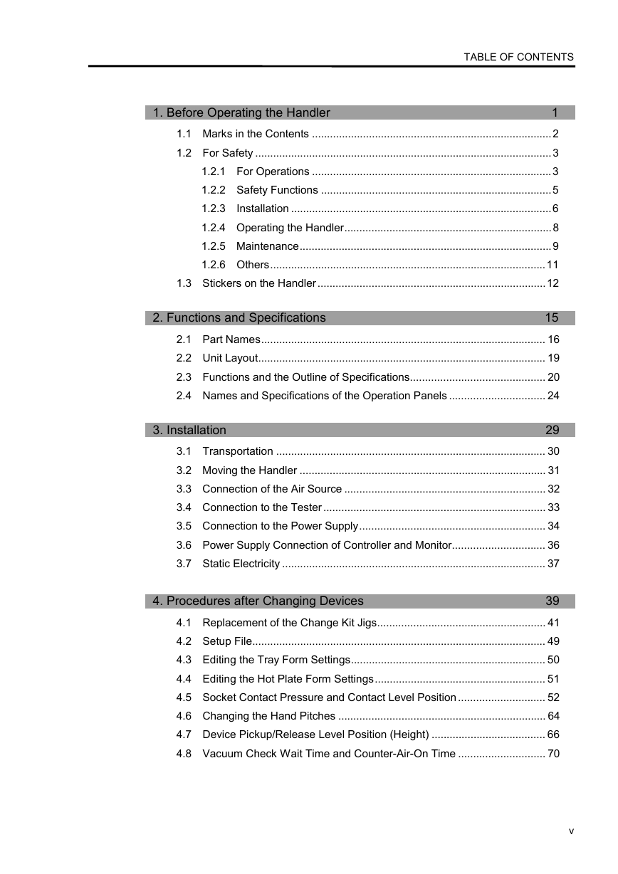
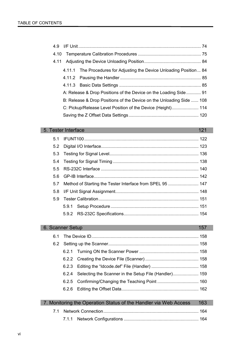
TABLE OF CONTENTS
1. Before Operating the Handler
2. Functions and Specifications
3. Installation
4. Procedures after Changing Devices
5. Tester Interface
6. Scanner Setup
7. Monitoring the Operation Status of the Handler via Web Access
8. I/O Map
Chapter 1 Before Operating the Handler
1.1 Marks in the Contents
1.2 For Safety
1.2.1 For Operations
Before Operations
During Operations
Range of Allowed Operation and Password
Operation Panels
1.2.2 Safety Functions
Covers, Doors and Safety Switches
Emergency Stop Switches
Confirmation of Safety Functions
1.2.3 Installation
Transportation and Installation
Connection to the Tester
Environment
Piping and Wiring
Setting Up
Connecting Cable or Connectors
1.2.4 Operating the Handler
Automatic Operations
Replacing the Change Kit Jigs
Adjustment Operations
Solving Jamming
1.2.5 Maintenance
Maintenance
Teaching
Adjustment Operations
Replacement of the Electrical Unit
1.2.6 Others
1.3 Stickers on the Handler
Chapter 2 Functions and Specifications
2.1 Part Names
2.1.1 Front View (Loader/Unloader side)
2.1.2 Inside the Hinged Doors
2.1.3 Lateral View
2.1.4 Back View (Tester side)
2.2 Unit Layout
2.3 Functions and the Outline of Specifications
1. Tray Loader
2. Loading Robot: Input Arm
3. Tray transporting Robot: Empty Tray Arm
4. Hot Plates
5. Shuttle 1 and 2
6. Index Unit: Test Arm 1 and 2
7. Unloading Robot: Output Arm
8. Tray Unloader
9. Contact Test Sockets
10. Fixed Tray(s)
11. Main Frame, Cover and Door
12. IC Lead Scanner (option)
13. Empty Tray Unloader (option)
14. Empty Tray Loader (option)
2.4 Names and Specifications of the Operation Panels
2.4.1 Names of the Operation Panels
2.4.2 Specifications of the Operation Panels
Chapter 3 Installation
3.1 Transportation
3.2 Moving the Handler
3.3 Connection of the Air Source
3.4 Connection to the Tester
3.5 Connection to the Power Supply
3.6 Power Supply Connection of Controller and Monitor
Reference: To Quit Software
3.7 Static Electricity
3.7.1 Reducing Static Electricity by the Attaching Ionizer (Option)
3.7.2 Dissipative Process and Change Kit Jigs with Dissipative Materials (Option)
Chapter 4 Procedures after Changing Devices
4.10 Temperature Calibration Procedures
4.10.1 Preparation
When setting the offset values manually (as conventionally done)
When automatically calibrating using the data-logger
4.10.2 Manual Calibration Procedure
4.10.3 Automatic Calibration Procedure
4.11 Adjusting the Device Unloading Position
4.11.1 The Procedures for Adjusting the Device Unloading Position
Summary of Procedure
4.11.2 Pausing the Handler
4.11.3 Basic Data Settings
(1) The [Tray Form] Dialog
(2) The [Hot Plate Form] Dialog
(3) The [Input Arm Condition] Dialog
(4) The [Index Arm Condition] Dialog
(5) The [Output Arm Condition] Dialog
A : Release & Drop Positions of the Device on the Loading Side
A-1 : Release & Drop Position from the Loading Tray to the Shuttle(s) on the Loading
Side (in the Ambient mode)
Check Point
Preparation
Procedure
A-2 :Release & Drop Position from the Loading Tray to the Hot Plate
(in the High-Temperature mode)
Check Points
Preparation
Procedure
A-3 :Release & Drop position from the Hot Plate to the Shuttle(s) on the Loading Side
(in High-Temperature Mode)
Check Points
Preparation
Procedure
B : Release & Drop Positions of the Device on the Unloading Side
(in Ambient and High Temperature Modes)
B-1 : Release & Drop Position from the Shuttle to the Unloader 1 Tray
(in Ambient and High Temperature Modes)
Check Points
Preparation
Procedure
C : Pickup/Release Level Position of the Device (Height)
C-1 : Pickup Level Position (Height) from the Loading Tray
(in Ambient & High Temperature Modes)
To Start the Suction at a Higher Level than Currently Set:
To Start the Suction at a Lower level than Currently Set:
C-2 : Release & Drop Level Position (Height) into the Shuttle on the Loading Side
(in the Ambient & High-Temperature Modes)
To Release & Drop the Device at a Higher Level Position than the
Currently Set:
To Release & Drop the Device at a Lower Level Position than
Currently Set:
C-3 : Pickup Level Position (height) from the Shuttle on the Unloading Side
(in Ambient & High-Temperature Modes).
To Start the Suction at a Higher Level than Currently Set:
To Start the Suction at a Lower Level than Currently Set:
C-4 : Release & Drop Level Position (height) onto the Hot Plate
(only in the High Temperature Mode)
To Release & Drop the Device at a Higher Level Position than
Currently Set:
To Release & Drop the Device at a Lower Level Position than
Currently Set:
C-5 : Pickup Level Position (height) from the Hot Plate (only High-Temperature Mode)
To Start the Suction at a Higher Level of Currently Set:
To Start the Suction at a Lower Level than Currently Set:
C-6 : Release & Drop Level Position (height) onto the Unloading Tray
(in the Ambient & High-Temperature Modes)
To Release & Drop the Device at a Higher Position than
Currently Set:
To Release & Drop the Device at a Lower Position than Currently
Set:
Saving the Z Offset Data Settings
4.1 Replacement of the Change Kit Jigs
Set of Change Kit Jigs
4.1.1 Replacement of the Input Arm Hand Jigs
4.1.2 Replacement of the Hot Plate Jigs
4.1.3 Replacement of the Shuttle Jigs
4.1.4 Replacement of the Test Hand Jigs
4.1.5 Replacement of the Output Arm Jigs
4.1.6 Replacement of the Socket Guide Jigs
4.1.7 Replacement of the Hand Pitch Jigs
4.2 Setup File
4.3 Editing the Tray Form Settings
4.4 Editing the Hot Plate Form Settings
4.5 Socket Contact Pressure and Contact Level Position
4.5.1 Showing the [Contact Parameter] Dialog
4.5.2 Changing the Handler Mode
4.5.3 Setting the Contact Pressure
A: Operating the Regulator by Hand
Regulator for Air Pressure Adjustment
B: Using an Optional Electropnuematic Regulator
4.5.4 Starting the Handler
When “Height Calibration” mode is selected:
When “Height Adjustment (Contact test)” mode is selected:
When “Manual Calibration” is selected:
Reference: Operation Sequence
Height Calibration
Height Adjustment (Contact test)
4.5.5 Loading the Contact Level Position (Height) Data
Reference: Torque Control Mode
4.5.6 Adjusting the Contact Level Position (Height) Data
4.6 Changing the Hand Pitches
4.7 Device Pickup/Release Level Position (Height)
4.7.1 Shuttle Position on the Loading Side
4.7.2 Shuttle Position on the Unloading Side
4.7.3 Input the Values
4.8 Vacuum Check Wait Time and Counter-Air-On Time
4.8.1 Adjusting the Input Arm
4.8.2 Adjusting the Index Arm
4.8.3 Adjusting the Output Arm
4.9 I/F Unit
Chapter 5 Tester Interface
5.1 IFUNT100
Appearance
5.2 Digital I/O Interface
5.2.1 [DIO Interface Configuration] Dialog
Start Signal
DUT Signal
End Signal
Multiple
Tester Calibration (RS-232C)
Category Signal
[Name]
5.2.2 Signals
START Signal
END Signal
DUT Signal
Category Data Signal
5.2.3 Type and Outline of I/F Unit Communication
Terms
5.2.4 Basic Timing Chart and Features of Signals
“5Bit Bit”, “5Bit Binary” or “10Bit”
“5Bit Bit with L_Dut” or “5Bit Binary with L_Dut”
“5Bit Bit with H_Dut” or “5Bit Binary with H_Dut”
“5Bit Bit 1 Start with L_Dut” or “5Bit Binary 1 Start with L_Dut”
“5Bit Bit 1 Start with H_Dut” or “5Bit Binary 1 Start with H_Dut”
“5Bit Bit with L_Dut & Reset”
“5Bit Bit with H_Dut &Reset”
Signals and Timing of Parameter
5.3 Testing for Signal Level
5.4 Testing for Signal Timing
5.5 RS-232C Interface
5.6 GP-IB Interface
5.6.1 Outline of GP-IB Interface
5.6.2 Signal Assignment
5.6.3 Command Format
5.6.4 Commands
1. Tester →Handler
2. Handler →Tester
Operation Sequence
5.7 Method of Starting the Tester Interface from SPEL 95
5.8 I/F Unit Signal Assignment
5.8.1 I/F Unit Signal Assignment
5.8.2 Signal Assignment in Normal Setting “5bit bit ” (DUT Signal is Unused.)
5.8.3 Signal Assignment in Normal Setting “10bit bit ”
5.9 Tester Calibration
5.9.1 Setup Procedure
Hardware Setting
Setting the Tester Program
The Handler Settings
5.9.2 RS-232C Specifications
The RS ‐232C Commands
Operation Sequence
Chapter 6 Scanner Setup
6.1 The Device ID
6.2 Setting up the Scanner
6.2.1 Turning ON the Scanner Power
6.2.2 Creating the Device File (Scanner)
6.2.3 Editing the “Idcode.def ” File (Handler)
6.2.4 Selecting the Scanner in the Setup File (Handler)
6.2.5 Confirming/Changing the Teaching Point
6.2.6 Editing the Offset Data
Chapter 7 Monitoring the Operation Status of the Handler via Web Access
7.1 Network Connection
7.1.1 Network Configurations
Peer-to-peer Connection
Hub Connection
7.1.2 Assignment of Connector Pins
7.1.3 Configuration of Pins on the Cable
7.1.4 Connection of the Cable
7.2 Setting up the Software
7.3 Web Access
Activating the WWW Server
Deactivating the WWW Server
7.3.1 A Case of Monitoring the Operation Status of the Handler via Internet Explorer
Setting of the IP Addresses
Activating the WWW Browser
7.3.2 Monitoring the Status of Connection
Setup of the WWW Dialog
WWW Dialog
7.3.3 Settings for Monitoring the Status of Connection
Setting up the [Server Configuration] Dialog
Exiting the [Server Configuration] Dialog
Server Configuration Dialog
[Server] Panel
[HTML] Panel
[Logging] Panel
[Status] Panel
[Alerts] Panel
Chapter 8 I/O Map
DU2 I/O INPUT
DU2 I/O OUTPUT
I/O-1 INPUT
I/O-1 OUTPUT
I/O-2 INPUT
I/O-2 OUTPUT
Remote I/O INPUT
Remote I/O OUTPUT
Remote I/O INPUT
Remote I/O OUTPUT
PC INPUT
PC I/O INPUT
INPUT
OUTPUT
Please direct any inquiries about the use of this manual to SEIKO EPSON CORPORATION




 2023年江西萍乡中考道德与法治真题及答案.doc
 2012年重庆南川中考生物真题及答案.doc
 2013年江西师范大学地理学综合及文艺理论基础考研真题.doc
 2020年四川甘孜小升初语文真题及答案I卷.doc
 2020年注册岩土工程师专业基础考试真题及答案.doc
 2023-2024学年福建省厦门市九年级上学期数学月考试题及答案.doc
 2021-2022学年辽宁省沈阳市大东区九年级上学期语文期末试题及答案.doc
 2022-2023学年北京东城区初三第一学期物理期末试卷及答案.doc
 2018上半年江西教师资格初中地理学科知识与教学能力真题及答案.doc
 2012年河北国家公务员申论考试真题及答案-省级.doc
 2020-2021学年江苏省扬州市江都区邵樊片九年级上学期数学第一次质量检测试题及答案.doc
 2022下半年黑龙江教师资格证中学综合素质真题及答案.doc