National Marine Electronics Association International Marine Electronics Association
Effective Date August 1, 2012
Preface
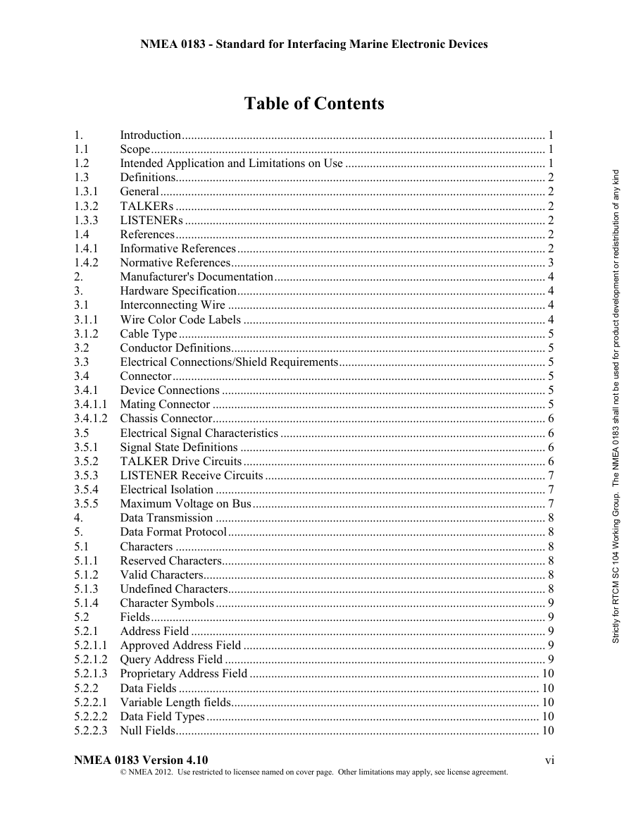
1. Introduction
1.1 Scope
1.2 Intended Application and Limitations on Use
1.3 Definitions
1.3.1 General
1.3.2 TALKERs
1.3.3 LISTENERs
1.4 References
1.4.1 Informative References
1.4.2 Normative References
2. Manufacturer's Documentation
3. Hardware Specification
3.1 Interconnecting Wire
3.1.1 Wire Color Code Labels
3.1.2 Cable Type
3.2 Conductor Definitions
3.3 Electrical Connections/Shield Requirements
3.4 Connector
3.4.1 Device Connections
3.4.1.1 Mating Connector
3.4.1.2 Chassis Connector
3.5 Electrical Signal Characteristics
3.5.1 Signal State Definitions
3.5.2 TALKER Drive Circuits
3.5.3 LISTENER Receive Circuits
3.5.4 Electrical Isolation
3.5.5 Maximum Voltage on Bus
4. Data Transmission
5. Data Format Protocol
5.1 Characters
5.1.1 Reserved Characters
5.1.2 Valid Characters
5.1.3 Undefined Characters
5.1.4 Character Symbols
5.2 Fields
5.2.1 Address Field
5.2.1.1 Approved Address Field
5.2.1.2 Query Address Field
5.2.1.3 Proprietary Address Field
5.2.2 Data Fields
5.2.2.1 Variable Length fields
5.2.2.2 Data Field Types
5.2.2.3 Null Fields
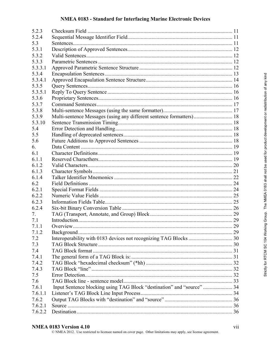
5.2.3 Checksum Field
5.2.4 Sequential Message Identifier Field
5.3 Sentences
5.3.1 Description of Approved Sentences
5.3.2 Valid Sentences
5.3.3 Parametric Sentences
5.3.3.1 Approved Parametric Sentence Structure
5.3.4 Encapsulation Sentences
5.3.4.1 Approved Encapsulation Sentence Structure
5.3.5 Query Sentences
5.3.5.1 Reply To Query Sentence
5.3.6 Proprietary Sentences
5.3.7 Command Sentences
5.3.8 Multi-sentence Messages (using the same formatter)
5.3.9 Multi-sentence Messages (using any different sentence formatters)
5.3.10 Sentence Transmission Timing
5.4 Error Detection and Handling
5.5 Handling of deprecated sentences
5.6 Future Additions to Approved Sentences
6. Data Content
6.1 Character Definitions
6.1.1 Reserved Characthers
6.1.2 Valid Characters
6.1.3 Character Symbols
6.1.4 Talker Identifier Mnemonics
6.2 Field Definitions
6.2.1 Special Format Fields
6.2.2 Numeric Value Fields
6.2.3 Information Fields Table
6.2.4 Six-bit Binary Conversion Table
7. TAG (Transport, Annotate, and Group) Block
7.1 Introduction
7.1.1 Overview
7.1.2 Background
7.2 Interoperability with 0183 devices not recognizing TAG Blocks
7.3 TAG Block Structure
7.4 TAG Block format
7.4.1 The general form of a TAG Block is:
7.4.2 TAG Block “hexadecimal checksum” (*hh)
7.4.3 TAG Block “line”
7.5 Error Detection
7.6 TAG Block line - sentence model
7.6.1 Input Sentence blocking using TAG Block “destination” and “source”
7.6.1.1 Listener’s TAG Block Line Input Process
7.6.2 Output TAG Blocks with “destination” and “source”
7.6.2.1 Source
7.6.2.2 Destination
7.6.2.3 Talker’s TAG Block Line Output Process
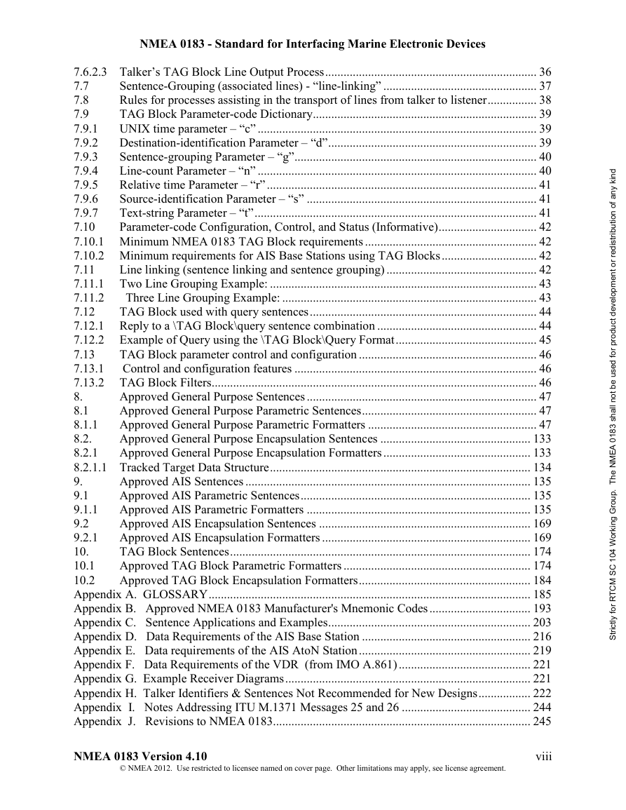
7.7 Sentence-Grouping (associated lines) - “line-linking”
7.8 Rules for processes assisting in the transport of lines from talker to listener
7.9 TAG Block Parameter-code Dictionary
7.9.1 UNIX time parameter – “c”
7.9.2 Destination-identification Parameter – “d”
7.9.3 Sentence-grouping Parameter – “g”
7.9.4 Line-count Parameter – “n”
7.9.5 Relative time Parameter – “r”
7.9.6 Source-identification Parameter – “s”
7.9.7 Text-string Parameter – “t”
7.10 Parameter-code Configuration, Control, and Status (Informative)
7.10.1 Minimum NMEA 0183 TAG Block requirements
7.10.2 Minimum requirements for AIS Base Stations using TAG Blocks
7.11 Line linking (sentence linking and sentence grouping)
7.11.1 Two Line Grouping Example:
7.11.2 Three Line Grouping Example:
7.12 TAG Block used with query sentences
7.12.1 Reply to a \TAG Block\query sentence combination
7.12.2 Example of Query using the \TAG Block\Query Format
7.13 TAG Block parameter control and configuration
7.13.1 Control and configuration features
7.13.2 TAG Block Filters
8. Approved General Purpose Sentences
8.1 Approved General Purpose Parametric Sentences
8.1.1 Approved General Purpose Parametric Formatters
Type of alarm 2
System indicator of original alarm source 2
Alarm’s description text 8
Alarm’s acknowledged state 7
Type of alarm 5
System indicator of original alarm source 2
Message description text 9
Water tight door switch setting 8
Door number or door open count 6
First division indicator 4
Event time 2
Operating location indicator 5
Position indicator of engine telegraph 3
Event time 1
Notes:
Message description text 9
Alarm’s acknowledgement state 8
Fire detector number or activation detection count 6
First division indicator 4
Event time 2
Packed binary field "n" 3,5
Packed binary field 3,5
Index of first packed binary field in sentence 1,5
Notes:
Measurement point ID
Number of engine or propeller shaft 7
Pitch mode indicator 5
RPM mode indicator 3
Lever demand status A= Data Valid, V = Data Invalid
Operating location indicator7
Azimuth demand6
Pitch demand value4
RPM demand value2
Pitch response value4
RPM response2
8.2. Approved General Purpose Encapsulation Sentences
8.2.1 Approved General Purpose Encapsulation Formatters
8.2.1.1 Tracked Target Data Structure
9. Approved AIS Sentences
9.1 Approved AIS Parametric Sentences
9.1.1 Approved AIS Parametric Formatters
9.2 Approved AIS Encapsulation Sentences
9.2.1 Approved AIS Encapsulation Formatters
10. TAG Block Sentences
10.1 Approved TAG Block Parametric Formatters
10.2 Approved TAG Block Encapsulation Formatters
Appendix A. GLOSSARY
Appendix B. Approved NMEA 0183 Manufacturer's Mnemonic Codes
Appendix C. Sentence Applications and Examples
Appendix D. Data Requirements of the AIS Base Station
D.3 Physical requirements for the presentation interface
D.4 Presentation interface data exchange
D.5 Base Station presentation interface output
D.6 Base Station presentation interface input
Appendix E. Data requirements of the AIS AtoN Station
Appendix F. Data Requirements of the VDR (from IMO A.861)
Appendix G. Example Receiver Diagrams
Appendix H. Talker Identifiers & Sentences Not Recommended for New Designs
APA – Autopilot Sentence "A"
BER – Bearing & Distance to Waypoint, Dead Reckoning, Rhumb Line
BPI – Bearing & Distance to Point of Interest
DBK – Depth Below Keel
DBS – Depth Below Surface
DCN – DECCA position
DRU – Dual Doppler Auxiliary Data
GDA – Dead Reckoning Positions Dead reckoned positions:
GLA – Loran-C Positions
GOA – OMEGA Positions $--GOA,hhmmss.ss,llll.ll,a,yyyyy.yy,a,c--c*hh
GXA – TRANSIT Positions
GTD – Geographical Position, Loran-C TDs
HCC – Compass Heading
HCD – Heading and Deviation
HDM – Heading, Magnetic
HDT – Heading, True
HVD – Magnetic Variation, Automatic
HVM – Magnetic Variation, Manually Set
IMA – Vessel Identification
MDA – Meteorological Composite
MHU – Humidity
MMB – Barometer
MTA – Air Temperature
MWH – Wave Height
MWS – Wind & Sea State
OLN – Omega Lane Numbers
OLW – Omega Lane Width
OMP – OMEGA
ONZ – Omega Zone Number
Rnn – Routes
SBK – Loran-C Blink Status
SCY – Loran-C Cycle Lock Status
SCD – Loran-C ECDs
SDB – Loran-C Signal Strength
SGD – Position Accuracy Estimate
SGR – Loran-C Chain Identifier
SIU – Loran-C Stations in Use
SLC – Loran-C Status
SNC – Navigation Calculation Basis
SNU – Loran-C SNR Status
SPS – Loran-C Predicted Signal Strength
SSF – Position Correction Offset
STC – Time Constant
STR – Tracking Reference
SYS – Hybrid System Configuration
TEC – TRANSIT Satellite Error Code & Doppler Count
TEP – TRANSIT Satellite Predicted Elevation
TGA – TRANSIT Satellite Antenna & Geoidal Heights -
TIF – TRANSIT Satellite Initial Flag
TRF – TRANSIT Fix Data
TRP – TRANSIT Satellite Predicted Direction of Rise
TRS – TRANSIT Satellite Operating Status
VCD – Current at Selected Depth
VPE – Speed, Dead Reckoned Parallel to True Wind
VTA – Actual Track
VTI – Intended Track
VWE – Wind Track Efficiency
VWR – Relative (Apparent) Wind Speed and Angle
VWT – True Wind Speed and Angle
WDC – Distance to Waypoint
WDR – Waypoint Distance, Rhumb Line
WFM – Route Following Mode
WNR – Waypoint-to-Waypoint Distance, Rhumb Line
YWP – Water Propagation Speed
YWS – Water Profile
ZAA – Time, Elapsed/Estimated
ZCD – Timer
ZEV – Event Timer
ZLZ – Time of Day
ZZU – Time, UTC
Appendix I. Notes Addressing ITU M.1371 Messages 25 & 26
Appendix J. Revisions to NMEA 0183





 2023年江西萍乡中考道德与法治真题及答案.doc
 2012年重庆南川中考生物真题及答案.doc
 2013年江西师范大学地理学综合及文艺理论基础考研真题.doc
 2020年四川甘孜小升初语文真题及答案I卷.doc
 2020年注册岩土工程师专业基础考试真题及答案.doc
 2023-2024学年福建省厦门市九年级上学期数学月考试题及答案.doc
 2021-2022学年辽宁省沈阳市大东区九年级上学期语文期末试题及答案.doc
 2022-2023学年北京东城区初三第一学期物理期末试卷及答案.doc
 2018上半年江西教师资格初中地理学科知识与教学能力真题及答案.doc
 2012年河北国家公务员申论考试真题及答案-省级.doc
 2020-2021学年江苏省扬州市江都区邵樊片九年级上学期数学第一次质量检测试题及答案.doc
 2022下半年黑龙江教师资格证中学综合素质真题及答案.doc