Recommendation ITU-R BT.2100-1
(06/2017)
Image parameter values for high dynamic
range television for use in production and
international programme exchange
BT Series
Broadcasting service
(television)
�
ii
Rec. ITU-R BT.2100-1
Foreword
The role of the Radiocommunication Sector is to ensure the rational, equitable, efficient and economical use of the
radio-frequency spectrum by all radiocommunication services, including satellite services, and carry out studies without
limit of frequency range on the basis of which Recommendations are adopted.
The regulatory and policy functions of the Radiocommunication Sector are performed by World and Regional
Radiocommunication Conferences and Radiocommunication Assemblies supported by Study Groups.
Policy on Intellectual Property Right (IPR)
ITU-R policy on IPR is described in the Common Patent Policy for ITU-T/ITU-R/ISO/IEC referenced in Annex 1 of
Resolution ITU-R 1. Forms to be used for the submission of patent statements and licensing declarations by patent
holders are available from http://www.itu.int/ITU-R/go/patents/en where the Guidelines for Implementation of the
Common Patent Policy for ITU-T/ITU-R/ISO/IEC and the ITU-R patent information database can also be found.
Series of ITU-R Recommendations
(Also available online at http://www.itu.int/publ/R-REC/en)
Title
Satellite delivery
Recording for production, archival and play-out; film for television
Broadcasting service (sound)
Broadcasting service (television)
Fixed service
Mobile, radiodetermination, amateur and related satellite services
Radiowave propagation
Radio astronomy
Remote sensing systems
Fixed-satellite service
Space applications and meteorology
Frequency sharing and coordination between fixed-satellite and fixed service systems
Spectrum management
Satellite news gathering
Time signals and frequency standards emissions
Vocabulary and related subjects
Series
BO
BR
BS
BT
F
M
P
RA
RS
S
SA
SF
SM
SNG
TF
V
Note: This ITU-R Recommendation was approved in English under the procedure detailed in Resolution ITU-R 1.
ITU 2017
Electronic Publication
Geneva, 2017
All rights reserved. No part of this publication may be reproduced, by any means whatsoever, without written permission of ITU.
�
Rec. ITU-R BT.2100-1
1
RECOMMENDATION ITU-R BT.2100-11
Image parameter values for high dynamic range television for use in
production and international programme exchange
(2016-2017)
Scope
High Dynamic Range Television (HDR-TV) provides viewers with an enhanced visual experience by
providing images that have been produced to look correct on brighter displays, that provide much brighter
highlights, and that provide improved detail in dark areas. This Recommendation specifies HDR-TV image
parameters for use in production and international programme exchange using the Perceptual Quantization
(PQ) and Hybrid Log-Gamma (HLG) methods.
Keywords
High dynamic range, HDR, television, HDR-TV, image system parameters, television production,
international programme exchange, wide colour gamut, perceptual quantization, PQ, hybrid
log-gamma, HLG
The ITU Radiocommunication Assembly,
considering
that digital television image formats for HDTV and UHDTV have been specified by the
a)
ITU-R in Recommendations ITU-R BT.709 and ITU-R BT.2020;
b)
that these television image formats have been limited in the image dynamic range they can
provide due to their reliance on legacy cathode ray tube (CRT) characteristics that limit image
brightness and detail in dark areas;
that modern displays are capable of reproducing images at a higher luminance, greater
c)
contrast ratio and wider colour gamut than is conventionally employed in programme production;
d)
that viewers expect future television viewing to provide improved characteristics compared
with the current HDTV and UHDTV in terms of a more realistic sensation, greater transparency to
the real world and more accurate visual information;
that high dynamic range television (HDR-TV) has been shown to increase viewer
e)
enjoyment of television pictures;
f)
that HDR-TV provides a “step-change” improvement in viewer experience by means of
substantially increased brightness and detail in highlights and diffuse reflecting objects, while
providing greater detail in dark areas;
that the combination of extended dynamic range and extended colour gamut give HDR-TV
g)
a substantially larger colour volume;
that the HDR-TV image formats should have, where appropriate, a degree of compatibility
h)
with existing workflows and infrastructure;
1 Revisions to parameter values within this document should be compared to those in the previously
published version of this Recommendation.
�
2
Rec. ITU-R BT.2100-1
that a reference viewing environment including display parameters should be defined for
i)
HDR-TV image formats,
further considering
that due to rapid developments in HDR technology the ITU may wish to consider early updates and
improvements to this Recommendation,
recognizing
that Report ITU-R BT.2390 contains much information on two methods to achieve HDR-TV,
recommends
that for programme production and international exchange of HDR-TV, the perceptual quantization
(PQ) or Hybrid Log-Gamma (HLG) specifications described in this Recommendation should be
used.
NOTE – The PQ specification achieves a very wide range of brightness levels for a given bit depth
using a non-linear transfer function that is finely tuned to match the human visual system. The HLG
specification offers a degree of compatibility with legacy displays by more closely matching the
previously established television transfer curves. Report ITU-R BT.2390 provides additional
information on PQ and HLG, conversion between them, and compatibility with previous systems.
TABLE 1
Image spatial and temporal characteristics
Parameter
Image Container 1a Shape
Container Pixel count 1b
Horizontal × Vertical
Sampling lattice
Pixel aspect ratio
Pixel addressing
Values
16:9
7 680 × 4 320
3 840 × 2 160
1 920 × 1 080
Orthogonal
1:1 (square pixels)
Pixel ordering in each row is from left to right, and rows
are ordered from top to bottom.
Frame frequency (Hz)
120, 120/1.001,100, 60, 60/1.001, 50, 30, 30/1.001, 25, 24, 24/1.001
Image Format
Progressive
NOTE 1a – Container is used to define the horizontal and vertical constraints of the image format.
NOTE 1b – Productions should use the highest resolution image format that is practical. It is recognized that
in many cases high resolution productions will be down-sampled to lower resolution formats for
distribution. It is known that producing in a higher resolution format, and then electronically down-sampling
for distribution, yields superior quality than producing at the resolution used for distribution.
�
Rec. ITU-R BT.2100-1
3
TABLE 2
System colorimetry
Parameter
Optical spectrum
(informative)
Red primary (R)
monochromatic 630 nm
Primary
colours
Green primary
(G)
monochromatic 532 nm
Blue primary (B)
monochromatic 467 nm
Reference white
D65 per
ISO 11664-2:2007
Values
Chromaticity coordinates
(CIE, 1931)
x
0.708
0.170
0.131
y
0.292
0.797
0.046
0.3127
0.3290
Colour Matching Functions
CIE 1931
Table 3 specifies parameters to establish a reference viewing environment for critical viewing of
HDR programme material or completed programmes that can provide repeatable results from one
facility to another when viewing the same material. Viewing facilities can and will continue to be
established in many ways by entities involved in editing, colour correction, screening and the like,
and the specifications in this Table are not intended to suggest a need for absolute uniformity in
such facilities.
Reference viewing environment for critical viewing of HDR programme material
TABLE 3
Parameter
Surround and periphery 3a
Luminance of surround
Luminance of periphery
Ambient lighting
Viewing distance 3b
Peak luminance of display 3c
Minimum
luminance
display (black level) 3d
of
Values
Neutral grey at D65
5 cd/m2
≤ 5 cd/m2
Avoid light falling on the screen
For 1 920 × 1 080 format: 3.2 picture heights
For 3 840 × 2 160 format: 1.6 to 3.2 picture heights
For 7 680 × 4 320 format: 0.8 to 3.2 picture heights
≥ 1 000 cd/m2
≤ 0.005 cd/m2
NOTE 3a – “Surround” is the area surrounding a display that can affect the adaptation of the eye, typically
the wall or curtain behind the display; “periphery” is the remaining environment outside of the surround.
NOTE 3b – When picture evaluation involves resolution, the lower value of viewing distance should be
used. When resolution is not being evaluated, any viewing distance in the indicated range may be used.
NOTE 3c – This is not to imply this level of luminance must be achieved for full screen white, rather for
small area highlights.
NOTE 3d – The actual black level would be set using a “PLUGE” signal (under development) and may
differ from the indicated value.
�
4
Rec. ITU-R BT.2100-1
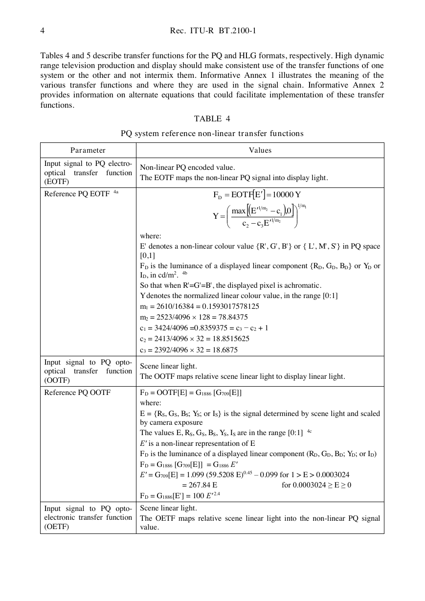
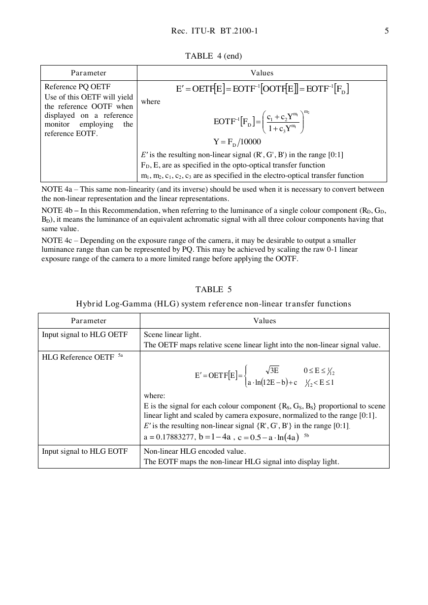
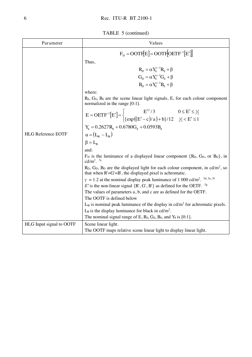
Tables 4 and 5 describe transfer functions for the PQ and HLG formats, respectively. High dynamic
range television production and display should make consistent use of the transfer functions of one
system or the other and not intermix them. Informative Annex 1 illustrates the meaning of the
various transfer functions and where they are used in the signal chain. Informative Annex 2
provides information on alternate equations that could facilitate implementation of these transfer
functions.
TABLE 4
PQ system reference non-linear transfer functions
Parameter
Input signal to PQ electro-
optical
function
(EOTF)
transfer
Reference PQ EOTF 4a
Values
Non-linear PQ encoded value.
The EOTF maps the non-linear PQ signal into display light.
Input signal to PQ opto-
optical
function
(OOTF)
transfer
Reference PQ OOTF
where:
E' denotes a non-linear colour value {R', G', B'} or { L', M', S'} in PQ space
[0,1]
FD is the luminance of a displayed linear component {RD, GD, BD} or YD or
ID, in cd/m2. 4b
So that when R'=G'=B', the displayed pixel is achromatic.
Y denotes the normalized linear colour value, in the range [0:1]
m1 = 2610/16384 = 0.1593017578125
m2 = 2523/4096 128 = 78.84375
c1 = 3424/4096 =0.8359375 = c3 − c2 + 1
c2 = 2413/4096 32 = 18.8515625
c3 = 2392/4096 32 = 18.6875
Scene linear light.
The OOTF maps relative scene linear light to display linear light.
FD = OOTF[E] = G1886 [G709[E]]
where:
E = {RS, GS, BS; YS; or IS} is the signal determined by scene light and scaled
by camera exposure
The values E, RS, GS, BS, YS, IS are in the range [0:1] 4c
E′ is a non-linear representation of E
FD is the luminance of a displayed linear component (RD, GD, BD; YD; or ID)
FD = G1886 [G709[E]] = G1886 E′
E′ = G709[E] = 1.099 (59.5208 E)0.45 – 0.099 for 1 > E > 0.0003024
for 0.0003024 ≥ E ≥ 0
FD = G1886[E'] = 100 E′
= 267.84 E
2.4
Input signal to PQ opto-
electronic transfer function
(OETF)
Scene linear light.
The OETF maps relative scene linear light into the non-linear PQ signal
value.
1221132110,max10000EOTFmmmDEcccEYYEF�
Rec. ITU-R BT.2100-1
5
Parameter
Reference PQ OETF
Use of this OETF will yield
the reference OOTF when
displayed on a reference
monitor
the
reference EOTF.
employing
where
TABLE 4 (end)
Values
E′ is the resulting non-linear signal (R', G', B') in the range [0:1]
FD, E, are as specified in the opto-optical transfer function
m1, m2, c1, c2, c3 are as specified in the electro-optical transfer function
NOTE 4a – This same non-linearity (and its inverse) should be used when it is necessary to convert between
the non-linear representation and the linear representations.
NOTE 4b – In this Recommendation, when referring to the luminance of a single colour component (RD, GD,
BD), it means the luminance of an equivalent achromatic signal with all three colour components having that
same value.
NOTE 4c – Depending on the exposure range of the camera, it may be desirable to output a smaller
luminance range than can be represented by PQ. This may be achieved by scaling the raw 0-1 linear
exposure range of the camera to a more limited range before applying the OOTF.
Hybrid Log-Gamma (HLG) system reference non-linear transfer functions
TABLE 5
Parameter
Input signal to HLG OETF
Values
Scene linear light.
The OETF maps relative scene linear light into the non-linear signal value.
HLG Reference OETF 5a
where:
E is the signal for each colour component {RS, GS, BS} proportional to scene
linear light and scaled by camera exposure, normalized to the range [0:1].
E′ is the resulting non-linear signal {R', G', B'} in the range [0:1].
a = 0.17883277,
,
5b
Input signal to HLG EOTF
Non-linear HLG encoded value.
The EOTF maps the non-linear HLG signal into display light.
DFEEE11EOTFOOTFEOTFOETF100001EOTF2113211DmmmDFYYcYccF112ln03OETF121121EcbEaEEEEab41aac4ln5.0�
6
Rec. ITU-R BT.2100-1
Parameter
Values
TABLE 5 (continued)
Thus,
where:
RS, GS, BS are the scene linear light signals, E, for each colour component
normalized in the range [0:1].
HLG Reference EOTF
and:
FD is the luminance of a displayed linear component {RD, GD, or BD}, in
cd/m2. 5c
RD, GD, BD are the displayed light for each colour component, in cd/m2, so
that when R'=G'=B', the displayed pixel is achromatic.
= 1.2 at the nominal display peak luminance of 1 000 cd/m2. 5d, 5e, 5f
E′ is the non-linear signal {R', G', B'} as defined for the OETF. 5g
The values of parameters a, b, and c are as defined for the OETF.
The OOTF is defined below
LW is nominal peak luminance of the display in cd/m2 for achromatic pixels.
LB is the display luminance for black in cd/m2.
The nominal signal range of E, RS, GS, BS, and YS is [0:1].
HLG Input signal to OOTF
Scene linear light.
The OOTF maps relative scene linear light to display linear light.
EEFD1OETFOOTFOOTFβββ1γ1γ1γSSDSSDSSDBYBGYGRYRBBWSSSSLLLBGRYEbacEEEEEβα0593.06780.02627.0112/}/{exp03/OETF212121�




 2023年江西萍乡中考道德与法治真题及答案.doc
 2012年重庆南川中考生物真题及答案.doc
 2013年江西师范大学地理学综合及文艺理论基础考研真题.doc
 2020年四川甘孜小升初语文真题及答案I卷.doc
 2020年注册岩土工程师专业基础考试真题及答案.doc
 2023-2024学年福建省厦门市九年级上学期数学月考试题及答案.doc
 2021-2022学年辽宁省沈阳市大东区九年级上学期语文期末试题及答案.doc
 2022-2023学年北京东城区初三第一学期物理期末试卷及答案.doc
 2018上半年江西教师资格初中地理学科知识与教学能力真题及答案.doc
 2012年河北国家公务员申论考试真题及答案-省级.doc
 2020-2021学年江苏省扬州市江都区邵樊片九年级上学期数学第一次质量检测试题及答案.doc
 2022下半年黑龙江教师资格证中学综合素质真题及答案.doc