Indy® R2000 Reader Chip (IPJ-R2000)
Electrical, Mechanical, & Thermal Specification
Indy® R2000 Reader Chip Overview
Air Interface Protocol
EPCglobal UHF Class 1 Gen 2 / ISO 18000-6C
• DSB, SSB, and PR-ASK transmit modulation modes
• Dense reader mode (DRM)
ISO 18000-6B, Ipico, and iP-X version1.07 not supported by Indy reference design
Integrated Power
Amplifier
Configurable up to 17 dBm. External power amplifier supported for high performance
applications
Transmit Output Power
Adjustable to > 25 dB
Modem
Configurable digital baseband
Operating Frequencies
840–960 MHz
Package
Power
Process
RSSI
Sensitivity
64-pin 9 mm x 9 mm x 0.85 mm QFN
Low power consumption, 1100 to 880 mW configuration dependant; 200μW standby
0.18 μm SiGe BiCMOS
Per tag, configurable bandwidth
-110 dBm; -95 dBm (DRM); -84dBm (DRM) with +10dBm carrier
Supported Regions
US, Canada, and other regions following US FCC 47 CFG Ch. 1 Part 15
Europe and other regions following ETSI EN 302 208-1 (V1.4.1)
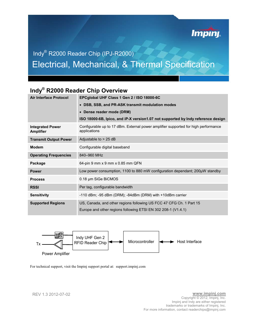
Tx
Power Amplifier
Indy UHF Gen 2
RFID Reader Chip
Microcontroller
Host Interface
For technical support, visit the Impinj support portal at: support.impinj.com
REV 1.3 2012-07-02
www.impinj.com
Copyright © 2012, Impinj, Inc.
Impinj and Indy are either registered
trademarks or trademarks of Impinj, Inc.
For more information, contact readerchips@impinj.com
�
Indy® R2000 Electrical, Mechanical, & Thermal Specification
TABLE OF CONTENTS
1
2.1
3.1
5.1.1
5.1.2
5.1.3
5.1.4
5.1.5
INTRODUCTION ................................................................................................................................................ 1
1.1 TERMINOLOGY ................................................................................................................................................. 1
1.2 REFERENCE DOCUMENTS ................................................................................................................................. 2
2 ABOUT THIS DOCUMENT ............................................................................................................................... 4
INDY R2000 READER CHIP DIAGRAMS............................................................................................................. 4
3 PIN LISTING/SIGNAL DEFINITIONS ............................................................................................................ 6
PIN LISTING AND SIGNAL DEFINITIONS ............................................................................................................. 6
4 ELECTRICAL SPECIFICATIONS ................................................................................................................... 8
4.1 ABSOLUTE MAXIMUM RATINGS ....................................................................................................................... 8
4.2 OPERATING CONDITIONS .................................................................................................................................. 8
4.3 TRANSCEIVER FUNCTIONAL SPECIFICATIONS ................................................................................................... 9
5 FUNCTIONAL DESCRIPTION ....................................................................................................................... 13
5.1 ANALOG RECEIVER DATA PATH ..................................................................................................................... 14
Receiver Front-end Circuitry ................................................................................................................. 14
Local Oscillator Input ............................................................................................................................ 14
Receive RF Interface .............................................................................................................................. 15
Self-Jammer Cancellation Block ............................................................................................................ 15
Receive Baseband Interface ................................................................................................................... 18
5.2 ANTENNA CONFIGURATION SCENARIOS ......................................................................................................... 19
5.3 RF POWER DETECTION .................................................................................................................................. 20
5.4 TRANSMITTER MODES ................................................................................................................................... 21
Full Power Non-linear Mode (DSB-ASK) .............................................................................................. 21
Low Power Non-linear Mode (DSB-ASK) .............................................................................................. 21
Linear Mode ........................................................................................................................................... 21
6 FREQUENCY GENERATION ......................................................................................................................... 23
INTERNAL SYNTHESIZER ................................................................................................................................. 23
7 DEVICE CONTROL AND PROGRAMMING ............................................................................................... 25
7.1
SERIAL INTERFACE ......................................................................................................................................... 26
Parallel Interface ................................................................................................................................... 27
7.2 REGISTER MAP ............................................................................................................................................... 28
8 PERFORMANCE CHARACTERISTICS - PRELIMINARY ....................................................................... 59
8.1 CARRIER SETTLING TIME ............................................................................................................................... 59
8.2 RX SENSITIVITY TESTING ............................................................................................................................... 60
8.3 TRANSMIT OUTPUT SPECTRAL TESTING ......................................................................................................... 63
8.4 ANALOG (GROSS) POWER CONTROL ................................................................................................................ 68
8.5 DIGITAL POWER CONTROL .............................................................................................................................. 69
8.6 ADC TESTING ................................................................................................................................................ 69
8.7 AUX. DAC TESTING ....................................................................................................................................... 70
9 PACKAGE INFORMATION............................................................................................................................ 71
9.1
PACKAGE INFORMATION ................................................................................................................................ 71
NOTICES: .................................................................................................................................................................. 73
5.4.1
5.4.2
5.4.3
6.1
7.1.1
Revision 1.3, Copyright © 2012, Impinj, Inc.
iii
�
Indy® R2000 Electrical, Mechanical, & Thermal Specification
FIGURES
FIGURE 1: INDY R2000 READER CHIP TOP LEVEL RF BLOCK DIAGRAM ........................................................................ 4
FIGURE 2: INDY R2000 READER CHIP SAMPLE APPLICATION ......................................................................................... 5
FIGURE 3: RECEIVER FRONT-END EXTERNAL INPUT INTERFACE CONFIGURED TO HANDLE +15 DBM SELF-JAMMER ... 14
FIGURE 4: RECEIVER FRONT-END EXTERNAL OUTPUT INTERFACE, INCLUDING DRM LC LOAD OF MIXER .................. 14
FIGURE 5: LOCAL OSCILLATOR INPUT EXTERNAL INTERFACES .................................................................................... 15
FIGURE 6: SELF-JAMMER CANCELLATION ARCHITECTURE ........................................................................................... 16
FIGURE 7: THEORETICAL OUTPUT AFTER SELF-JAMMER CANCELLATION RELATIVE TO FULL SCALE. ............................. 17
FIGURE 8: SELF-JAMMER CANCELLATION GRID AND CALIBRATION EXAMPLES. ............................................................. 18
FIGURE 9: SINGLE ANTENNA SCENARIO ....................................................................................................................... 20
FIGURE 10: DUAL ANTENNA SCENARIO ........................................................................................................................ 20
FIGURE 11: INDY® R2000 READER CHIP TRANSMIT WITH EXTERNAL PA (DSB ASK) ................................................. 21
FIGURE 12: VCO TUNING CURVES ................................................................................................................................ 23
FIGURE 13: SYNTHESIZER PHASE NOISE ........................................................................................................................ 24
FIGURE 14: PLL SETTLING TIME ................................................................................................................................... 24
FIGURE 15: SERIAL INTERFACE FRAME FORMAT .......................................................................................................... 26
FIGURE 16: SERIAL INTERFACE T2R TIMING ................................................................................................................ 26
FIGURE 17: SERIAL INTERFACE R2T TIMING ................................................................................................................ 27
FIGURE 18: PARALLEL INTERFACE READ TIMING ......................................................................................................... 27
FIGURE 19: PARALLEL INTERFACE WRITE TIMING........................................................................................................ 28
FIGURE 20: CARRIER SETTLING TIME ........................................................................................................................... 59
FIGURE 21: PACKET ERROR RATE TEST SETUP - MONOSTATIC CONFIGURATION ......................................................... 60
FIGURE 22: PACKET ERROR RATE TEST SETUP - BI-STATIC CONFIGURATION .............................................................. 61
FIGURE 23: PACKET ERROR RATE TEST SETUP - REAL TAG ......................................................................................... 61
FIGURE 24: DSB-ASK, TARI=25ΜS, X=0.5 AND 1.0 .................................................................................................... 63
FIGURE 25: PR-ASK, TARI=25ΜS, X=0.5 AND 1.0 ....................................................................................................... 63
FIGURE 26: SSB-ASK, TARI=25ΜS, X=0.5 AND 1.0 ..................................................................................................... 64
FIGURE 27: DSB-ASK, TARI=12.5ΜS, X=0.5 AND 1.0 ................................................................................................. 64
FIGURE 28: PR-ASK, TARI=12.5ΜS, X=0.5 AND 1.0 .................................................................................................... 65
FIGURE 29: SSB-ASK, TARI=12.5ΜS, X=0.5 AND 1.0 .................................................................................................. 65
FIGURE 30: DSB-ASK, TARI=6.25ΜS, X=0.5 AND 1.0 ................................................................................................. 66
FIGURE 31: PR-ASK, TARI=6.25ΜS, X=0.5 AND 1.0 .................................................................................................... 66
FIGURE 32: SSB-ASK, TARI=6.25ΜS, X=0.5 AND 1.0 .................................................................................................. 67
FIGURE 33: PR-ASK, TARI=25ΜS, X=1.0 TURBO MODE (+15DBM CW POWER) .......................................................... 67
FIGURE 34: OUTPUT POWER V. ANALOG CONTROL STATE ............................................................................................. 68
FIGURE 35: INL AND DNL FOR AUXILIARY ADC ......................................................................................................... 68
FIGURE 36: OUTPUT POWER V. SCALAR STATE .............................................................................................................. 69
FIGURE 37: ADC COUNT V. INPUT VOLTAGE ................................................................................................................. 69
FIGURE 38: INL AND DNL FOR AUXILIARY ADC ......................................................................................................... 69
FIGURE 39: DACS OUTPUT VOLTAGE ............................................................................................................................ 70
FIGURE 40: INL AND DNL FOR DAC0 AND DAC1 ....................................................................................................... 70
FIGURE 41: INDY®R2000 READER CHIP PACKAGE TOP VIEW ...................................................................................... 71
FIGURE 42: INDY®R2000 READER CHIP PACKAGE DIMENSIONS .................................................................................. 72
TABLES
TABLE 1: TERMINOLOGY ................................................................................................................................................ 1
TABLE 2: PROTOCOL SPECIFICATION DOCUMENTS ......................................................................................................... 3
TABLE 3: LOCAL REGULATION DOCUMENTS .................................................................................................................. 3
TABLE 4: SUPPLEMENTAL DOCUMENTS.......................................................................................................................... 3
TABLE 5: PIN LISTING AND SIGNAL DEFINITIONS ............................................................................................................ 6
TABLE 6: ABSOLUTE MAXIMUM RATINGS ...................................................................................................................... 8
TABLE 7: OPERATING CONDITIONS ................................................................................................................................ 8
TABLE 8: POWER CONSUMPTION SPECIFICATIONS IN MISSION MODE (READING TAGS) AND RESET .............................. 9
TABLE 9: INDY R2000 READER CHIP—RECEIVER SPECIFICATIONS................................................................................ 9
iv
Revision 1.3, Copyright © 2012, Impinj, Inc.
�
Indy® R2000 Electrical, Mechanical, & Thermal Specification
TABLE 10: INDY®R2000 READER CHIP—TRANSMITTER SPECIFICATIONS ................................................................... 10
TABLE 11: INDY®R2000 READER CHIP EXTERNAL LO INPUT ..................................................................................... 11
TABLE 12: INDY®R2000 READER CHIP ENVELOPE DETECTORS ................................................................................... 11
TABLE 13: INDY®R2000 READER CHIP SYNTHESIZER .................................................................................................. 11
TABLE 14: INDY R2000 READER CHIP CLOCK OUTPUT, DACS, AND ADCS ................................................................ 12
TABLE 15: INDY®R2000 READER CHIP DIGITAL INTERFACE ........................................................................................ 12
TABLE 16: PHASE NOISE V. VCO CURRENT .................................................................................................................. 23
TABLE 17: INDY R2000 MODES ................................................................................................................................... 25
TABLE 18: PIN FUNCTIONALITY PER MODE .................................................................................................................. 25
TABLE 19: SERIAL INTERFACE TIMING REQUIREMENTS ............................................................................................... 27
TABLE 20: PARALLEL INTERFACE TIMING CONDITIONS ................................................................................................ 28
TABLE 21: REGISTER MAP ............................................................................................................................................ 28
TABLE 22: REGISTER MAP TYPE DEFINITION ............................................................................................................... 58
TABLE 23: CONVERSION TABLE ................................................................................................................................... 58
TABLE 24: ISO 18000-6C SENSITIVITY SUMMARY ....................................................................................................... 62
Revision 1.3, Copyright © 2012, Impinj, Inc.
v
�
Indy® R2000 Electrical, Mechanical, & Thermal Specification
1
Introduction
Industry leading modem architecture uses modern digital signal processing which ensures high read reliability
Self-jammer cancellation circuitry (market exclusive technology, ensures read reliability even with high antenna reflections)
Fully integrated voltage controlled oscillator (VCO) with world wide RFID coverage
Integrated Power Amplifier (PA)
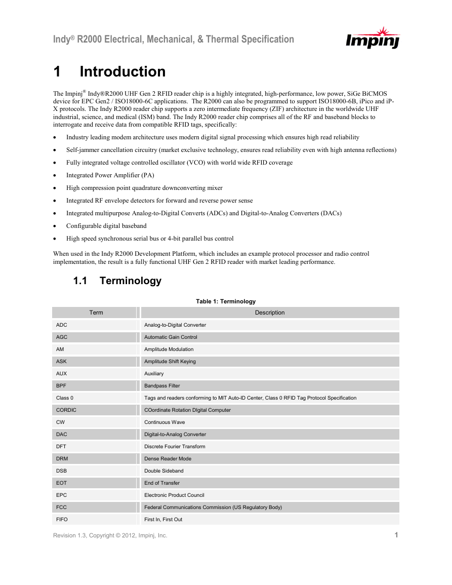
The Impinj® Indy®R2000 UHF Gen 2 RFID reader chip is a highly integrated, high-performance, low power, SiGe BiCMOS
device for EPC Gen2 / ISO18000-6C applications. The R2000 can also be programmed to support ISO18000-6B, iPico and iP-
X protocols. The Indy R2000 reader chip supports a zero intermediate frequency (ZIF) architecture in the worldwide UHF
industrial, science, and medical (ISM) band. The Indy R2000 reader chip comprises all of the RF and baseband blocks to
interrogate and receive data from compatible RFID tags, specifically:
•
•
•
•
• High compression point quadrature downconverting mixer
•
•
• Configurable digital baseband
• High speed synchronous serial bus or 4-bit parallel bus control
Integrated RF envelope detectors for forward and reverse power sense
Integrated multipurpose Analog-to-Digital Converts (ADCs) and Digital-to-Analog Converters (DACs)
When used in the Indy R2000 Development Platform, which includes an example protocol processor and radio control
implementation, the result is a fully functional UHF Gen 2 RFID reader with market leading performance.
1.1 Terminology
Term
Table 1: Terminology
Description
ADC
AGC
AM
ASK
AUX
BPF
Class 0
CORDIC
CW
DAC
DFT
DRM
DSB
EOT
EPC
FCC
FIFO
Analog-to-Digital Converter
Automatic Gain Control
Amplitude Modulation
Amplitude Shift Keying
Auxiliary
Bandpass Filter
Tags and readers conforming to MIT Auto-ID Center, Class 0 RFID Tag Protocol Specification
COordinate Rotation DIgital Computer
Continuous Wave
Digital-to-Analog Converter
Discrete Fourier Transform
Dense Reader Mode
Double Sideband
End of Transfer
Electronic Product Council
Federal Communications Commission (US Regulatory Body)
First In, First Out
Revision 1.3, Copyright © 2012, Impinj, Inc.
1
�
Indy® R2000 Electrical, Mechanical, & Thermal Specification
Term
Description
FIR
I
IF
IIR
I-Q
ISM
ISO
Finite Impulse Response
In-phase
Intermediate Frequency
Infinite Impulse Response
In-phase Quadrature
Industrial, Science, and Medical
International Standards Organization
ISO18000
Tags and Readers conforming to ISO/IEC FDIS 18000-6:2003(E)
LBT
LFSR
LNA
LO
LUT
MSB
MSps
NCO
PA
PER
PLL
PoE
PR
Q
RF
RFID
RSSI
RX
SJ
SJC
SSB
TBD
TX
TCXO
UHF
VCO
Listen Before Talk
Linear Feedback Shift Registers
Low Noise Amplifier
Local Oscillator
Lookup Table
Most Significant Bit
Mega Samples per Second
Numerically Controlled Oscillator
Power Amplifier
Packet Error Rate
Phase Locked Loop
Power over Ethernet
Phase Reversal
Quadrature-phase
Radio Frequency
Radio Frequency Identification
Received Signal Strength Indicator
Receiver
Self Jammer—also known as Tx carrier present at the Rx port
Self Jammer cancellation—circuitry that removes SJ from Rx port
Single Sideband
To Be Determined
Transmitter
Temperature Compensated Crystal Oscillator
Ultra High Frequency
Voltage Controlled Oscillator
1.2 Reference Documents
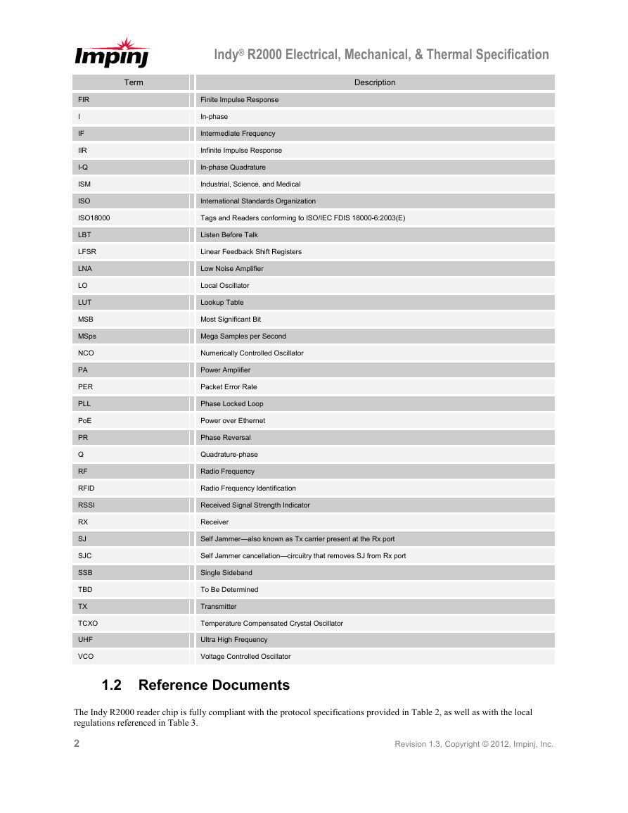
The Indy R2000 reader chip is fully compliant with the protocol specifications provided in Table 2, as well as with the local
regulations referenced in Table 3.
2
Revision 1.3, Copyright © 2012, Impinj, Inc.
�
Indy® R2000 Electrical, Mechanical, & Thermal Specification
Table 2: Protocol Specification Documents
Document
iPico, iP-X: Universal RFID protocol standard V1.07 July 2005
ISO/IEC FDIS 18000-6B Sept. 2004
ISO/IEC FDIS 18000-6C Jan. 2005
Table 3: Local Regulation Documents
Document
FCC 47 CFR Ch. 1, part 15 10-1-98 Edition
ETSI EN 302 208-1 V1.4.1
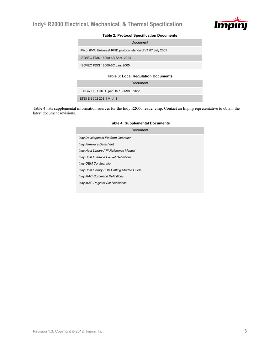
Table 4 lists supplemental information sources for the Indy R2000 reader chip. Contact an Impinj representative to obtain the
latest document revisions.
Table 4: Supplemental Documents
Document
Indy Development Platform Operation
Indy Firmware Datasheet
Indy Host Library API Reference Manual
Indy Host Interface Packet Definitions
Indy OEM Configuration
Indy Host Library SDK Getting Started Guide
Indy MAC Command Definitions
Indy MAC Register Set Definitions
Revision 1.3, Copyright © 2012, Impinj, Inc.
3
�
Indy® R2000 Electrical, Mechanical, & Thermal Specification
2 About This Document
This document constitutes the electrical, mechanical, and thermal specifications for the Indy R2000 reader chip. It contains a
functional overview, mechanical data, package signal locations, and targeted electrical specifications.
2.1
Indy R2000 Reader Chip Diagrams
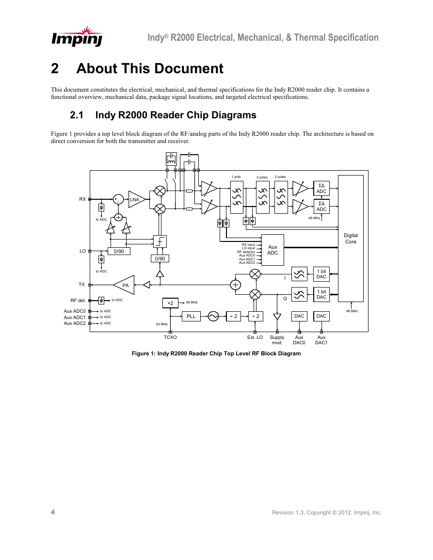
Figure 1 provides a top level block diagram of the RF/analog parts of the Indy R2000 reader chip. The architecture is based on
direct conversion for both the transmitter and receiver.
1 pole
2 poles
2 poles
RX
+ -+ -
LNA
to ADC
LO
0/90
0/90
RX input
LO input
RF detector
Aux ADC0
Aux ADC1
Aux ADC2
Aux
ADC
ΣΔ
ADC
ΣΔ
ADC
48 MHz
Digital
Core
PA
to ADC
to ADC
to ADC
to ADC
to ADC
TX
RF det.
Aux ADC0
Aux ADC1
Aux ADC2
×2
48 MHz
PLL
24 MHz
I
Q
1 bit
DAC
1 bit
DAC
÷ 2
÷ 2
DAC
DAC
48 MHz
TCXO
Ext. LO
Aux
DAC0
Figure 1: Indy R2000 Reader Chip Top Level RF Block Diagram
Supply
mod.
Aux
DAC1
4
Revision 1.3, Copyright © 2012, Impinj, Inc.
�


 2023年江西萍乡中考道德与法治真题及答案.doc
 2012年重庆南川中考生物真题及答案.doc
 2013年江西师范大学地理学综合及文艺理论基础考研真题.doc
 2020年四川甘孜小升初语文真题及答案I卷.doc
 2020年注册岩土工程师专业基础考试真题及答案.doc
 2023-2024学年福建省厦门市九年级上学期数学月考试题及答案.doc
 2021-2022学年辽宁省沈阳市大东区九年级上学期语文期末试题及答案.doc
 2022-2023学年北京东城区初三第一学期物理期末试卷及答案.doc
 2018上半年江西教师资格初中地理学科知识与教学能力真题及答案.doc
 2012年河北国家公务员申论考试真题及答案-省级.doc
 2020-2021学年江苏省扬州市江都区邵樊片九年级上学期数学第一次质量检测试题及答案.doc
 2022下半年黑龙江教师资格证中学综合素质真题及答案.doc