Standardized ARS Interface
Continental Engineering Services GmbH
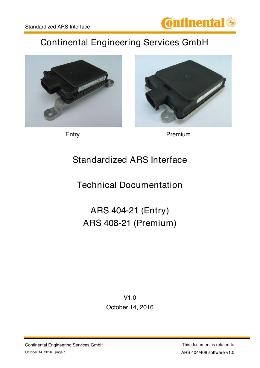
Entry Premium
Standardized ARS Interface
Technical Documentation
ARS 404-21 (Entry)
ARS 408-21 (Premium)
V1.0
October 14, 2016
Continental Engineering Services GmbH
October 14, 2016 page 1
This document is related to
ARS 404/408 software v1.0
�
Standardized ARS Interface
Table of Contents
1.
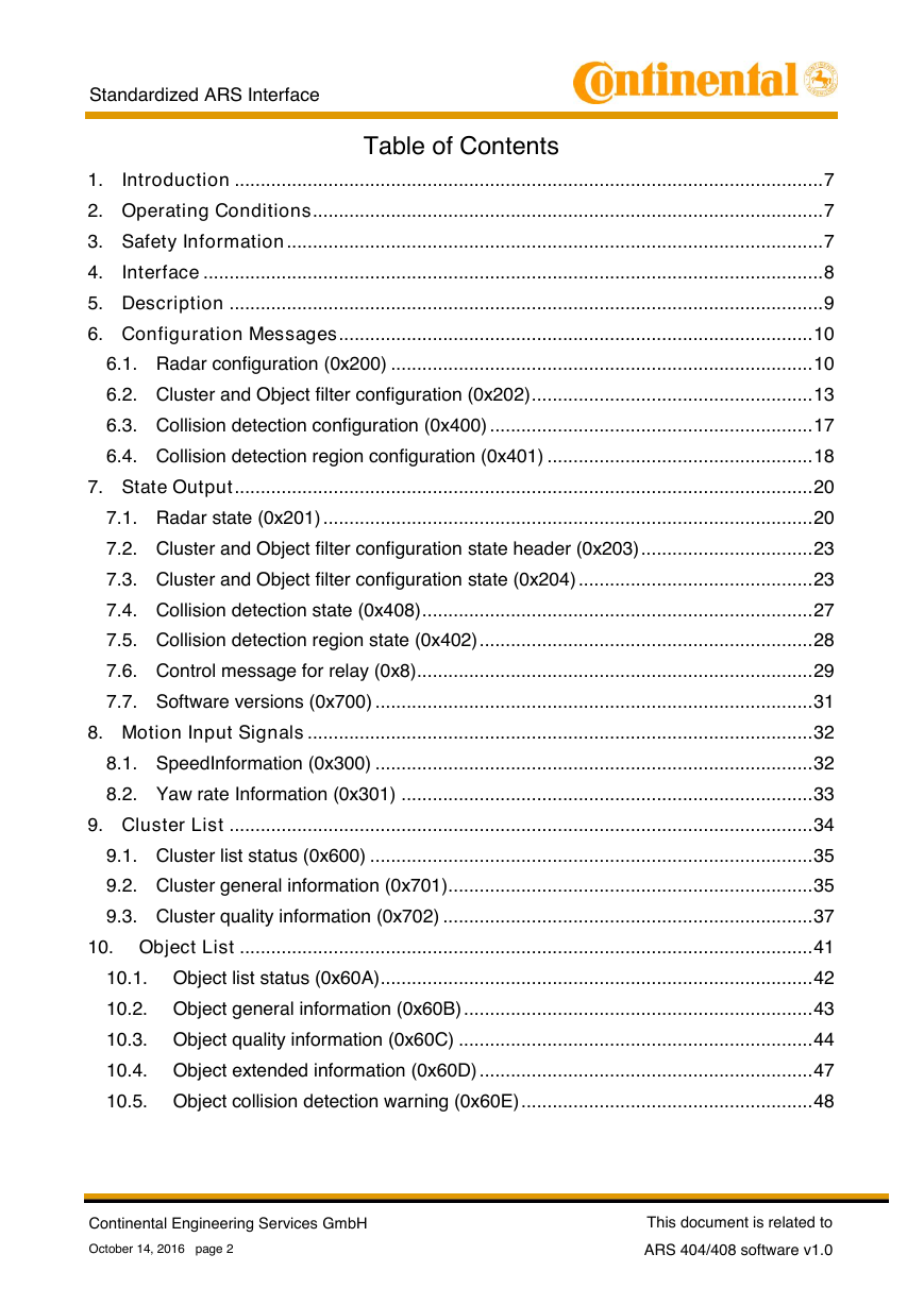
Introduction ................................................................................................................. 7
2. Operating Conditions .................................................................................................. 7
3. Safety Information ....................................................................................................... 7
4.
Interface ....................................................................................................................... 8
5. Description .................................................................................................................. 9
6. Configuration Messages ........................................................................................... 10
6.1. Radar configuration (0x200) ................................................................................. 10
6.2. Cluster and Object filter configuration (0x202) ...................................................... 13
6.3. Collision detection configuration (0x400) .............................................................. 17
6.4. Collision detection region configuration (0x401) ................................................... 18
7. State Output ............................................................................................................... 20
7.1. Radar state (0x201) .............................................................................................. 20
7.2. Cluster and Object filter configuration state header (0x203) ................................. 23
7.3. Cluster and Object filter configuration state (0x204) ............................................. 23
7.4. Collision detection state (0x408) ........................................................................... 27
7.5. Collision detection region state (0x402) ................................................................ 28
7.6. Control message for relay (0x8) ............................................................................ 29
7.7. Software versions (0x700) .................................................................................... 31
8. Motion Input Signals ................................................................................................. 32
8.1. SpeedInformation (0x300) .................................................................................... 32
8.2. Yaw rate Information (0x301) ............................................................................... 33
9. Cluster List ................................................................................................................ 34
9.1. Cluster list status (0x600) ..................................................................................... 35
9.2. Cluster general information (0x701) ...................................................................... 35
9.3. Cluster quality information (0x702) ....................................................................... 37
10. Object List .............................................................................................................. 41
10.1. Object list status (0x60A) ................................................................................... 42
10.2. Object general information (0x60B) ................................................................... 43
10.3. Object quality information (0x60C) .................................................................... 44
10.4. Object extended information (0x60D) ................................................................ 47
10.5. Object collision detection warning (0x60E) ........................................................ 48
Continental Engineering Services GmbH
October 14, 2016 page 2
This document is related to
ARS 404/408 software v1.0
�
Standardized ARS Interface
History
Version
Date
Chapter Change description
V1.0
14.10.2016
First released version
Continental Engineering Services GmbH
October 14, 2016 page 3
This document is related to
ARS 404/408 software v1.0
�
Standardized ARS Interface
Table of Figures
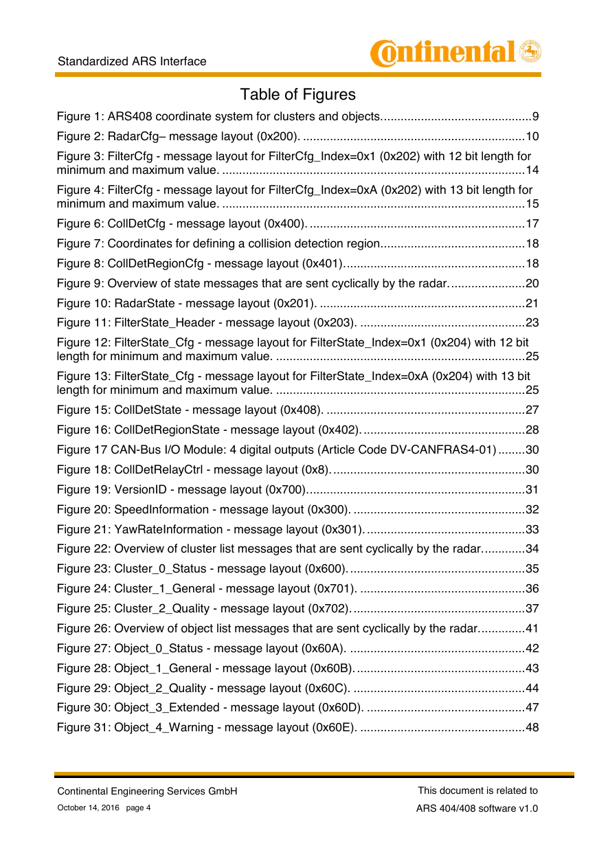
Figure 1: ARS408 coordinate system for clusters and objects. ............................................ 9
Figure 2: RadarCfg– message layout (0x200). .................................................................. 10
Figure 3: FilterCfg - message layout for FilterCfg_Index=0x1 (0x202) with 12 bit length for
minimum and maximum value. .......................................................................................... 14
Figure 4: FilterCfg - message layout for FilterCfg_Index=0xA (0x202) with 13 bit length for
minimum and maximum value. .......................................................................................... 15
Figure 6: CollDetCfg - message layout (0x400). ................................................................ 17
Figure 7: Coordinates for defining a collision detection region. .......................................... 18
Figure 8: CollDetRegionCfg - message layout (0x401). ..................................................... 18
Figure 9: Overview of state messages that are sent cyclically by the radar. ...................... 20
Figure 10: RadarState - message layout (0x201). ............................................................. 21
Figure 11: FilterState_Header - message layout (0x203). ................................................. 23
Figure 12: FilterState_Cfg - message layout for FilterState_Index=0x1 (0x204) with 12 bit
length for minimum and maximum value. .......................................................................... 25
Figure 13: FilterState_Cfg - message layout for FilterState_Index=0xA (0x204) with 13 bit
length for minimum and maximum value. .......................................................................... 25
Figure 15: CollDetState - message layout (0x408). ........................................................... 27
Figure 16: CollDetRegionState - message layout (0x402). ................................................ 28
Figure 17 CAN-Bus I/O Module: 4 digital outputs (Article Code DV-CANFRAS4-01) ........ 30
Figure 18: CollDetRelayCtrl - message layout (0x8). ......................................................... 30
Figure 19: VersionID - message layout (0x700). ................................................................ 31
Figure 20: SpeedInformation - message layout (0x300). ................................................... 32
Figure 21: YawRateInformation - message layout (0x301). ............................................... 33
Figure 22: Overview of cluster list messages that are sent cyclically by the radar. ............ 34
Figure 23: Cluster_0_Status - message layout (0x600). .................................................... 35
Figure 24: Cluster_1_General - message layout (0x701). ................................................. 36
Figure 25: Cluster_2_Quality - message layout (0x702). ................................................... 37
Figure 26: Overview of object list messages that are sent cyclically by the radar. ............. 41
Figure 27: Object_0_Status - message layout (0x60A). .................................................... 42
Figure 28: Object_1_General - message layout (0x60B). .................................................. 43
Figure 29: Object_2_Quality - message layout (0x60C). ................................................... 44
Figure 30: Object_3_Extended - message layout (0x60D). ............................................... 47
Figure 31: Object_4_Warning - message layout (0x60E). ................................................. 48
Continental Engineering Services GmbH
October 14, 2016 page 4
This document is related to
ARS 404/408 software v1.0
�
Standardized ARS Interface
Table of Tables
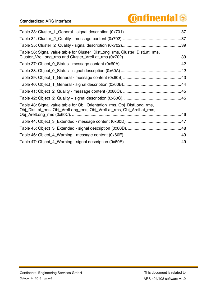
Table 1: Sensor CAN messages (exemplary for sensor ID 0). ............................................ 8
Table 2: RadarCfg– message content (0x200). ................................................................. 11
Table 3: RadarCfg – signal description (0x200). ................................................................ 12
Table 4: Possible filter criteria selectable with FilterCfg_Index. The columns C and O
specify if this filter can be applied to clusters or objects, respectively. ............................... 13
Table 5: FilterCfg - message content (0x202). ................................................................... 15
Table 6: FilterCfg - signal description (0x202). .................................................................. 16
Table 7: CollDetCfg - message content (0x400). ............................................................... 17
Table 8: CollDetCfg - signal description (0x400). ............................................................... 17
Table 9: CollDetRegionCfg - message content (0x401). .................................................... 19
Table 10: CollDetRegionCfg - signal description (0x401). ................................................. 19
Table 11: RadarState - message content (0x201). ............................................................ 21
Table 12: RadarState - signal description (0x201). ............................................................ 22
Table 13: FilterState_Header - message content (0x203). ................................................ 23
Table 14: FilterState_Header - signal description (0x203). ................................................ 23
Table 15: Possible filter criteria selectable with FilterState_Index. The columns C and O
specify if this filter can be applied to clusters or objects, respectively. ............................... 24
Table 16: FilterState_Cfg - message content (0x204). ...................................................... 25
Table 17: FilterState_Cfg - signal description (0x204). ...................................................... 27
Table 18: CollDetState - message content (0x408). .......................................................... 27
Table 19: CollDetState - signal description (0x408). .......................................................... 28
Table 20: CollDetRegionState - message content (0x402). ............................................... 28
Table 21: CollDetRegionState - signal description (0x402). ............................................... 29
Table 22: CollDetRelayCtrl - message content (0x8). ....................................................... 30
Table 23: CollDetRelayCtrl - signal description (0x8). ...................................................... 31
Table 24: VersionID - message content (0x700). ............................................................... 31
Table 25: VersionID – signal description (0x700). ............................................................. 31
Table 26: SpeedInformation - message content (0x300). .................................................. 32
Table 27: SpeedInformation – signal description (0x300). ................................................. 32
Table 28: YawRateInformation - message content (0x301). .............................................. 33
Table 29: YawRateInformation – signal description (0x301). ............................................. 33
Table 30: Cluster_0_Status - message content (0x600). ................................................... 35
Table 31: Cluster_0_Status – signal description (0x600). .................................................. 35
Table 32: Cluster_1_General - message content (0x701). ................................................ 36
Continental Engineering Services GmbH
October 14, 2016 page 5
This document is related to
ARS 404/408 software v1.0
�
Standardized ARS Interface
Table 33: Cluster_1_General - signal description (0x701). ................................................ 37
Table 34: Cluster_2_Quality - message content (0x702). .................................................. 37
Table 35: Cluster_2_Quality - signal description (0x702)................................................... 39
Table 36: Signal value table for Cluster_DistLong_rms, Cluster_DistLat_rms,
Cluster_VrelLong_rms and Cluster_VrelLat_rms (0x702).................................................. 39
Table 37: Object_0_Status - message content (0x60A). ................................................... 42
Table 38: Object_0_Status - signal description (0x60A) .................................................... 42
Table 39: Object_1_General - message content (0x60B). ................................................. 43
Table 40: Object_1_General - signal description (0x60B). ................................................. 44
Table 41: Object_2_Quality - message content (0x60C). .................................................. 45
Table 42: Object_2_Quality – signal description (0x60C). ................................................. 45
Table 43: Signal value table for Obj_Orientation_rms, Obj_DistLong_rms,
Obj_DistLat_rms, Obj_VrelLong_rms, Obj_VrelLat_rms, Obj_ArelLat_rms,
Obj_ArelLong_rms (0x60C). .............................................................................................. 46
Table 44: Object_3_Extended - message content (0x60D). .............................................. 47
Table 45: Object_3_Extended - signal description (0x60D). .............................................. 48
Table 46: Object_4_Warning - message content (0x60E). ................................................ 49
Table 47: Object_4_Warning - signal description (0x60E). ................................................ 49
Continental Engineering Services GmbH
October 14, 2016 page 6
This document is related to
ARS 404/408 software v1.0
�
Standardized ARS Interface
1.
Introduction
The ARS 400 is a Radar Sensor System developed by Continental for the Automotive
Industry to realize advanced driver assistance functions.
For the ARS408, the software of the sensor was adapted to use it also for general
purposes. With the simple software interface it is possible to connect the sensor to a CAN
network and to provide radar based environmental information to one or several evaluation
units. The sensor can also be configured via CAN.
2. Operating Conditions
Please refer to ARS 404/408-Technical Description.
3.
Safety Information
Please refer to ARS 404/408-Technical Description.
Continental Engineering Services GmbH
October 14, 2016 page 7
This document is related to
ARS 404/408 software v1.0
�
Standardized ARS Interface
4.
Interface
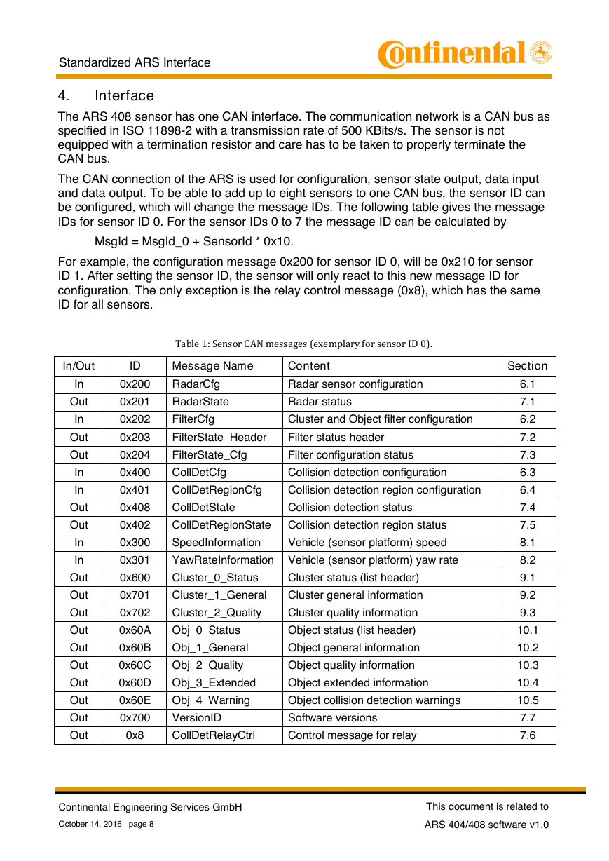
The ARS 408 sensor has one CAN interface. The communication network is a CAN bus as
specified in ISO 11898-2 with a transmission rate of 500 KBits/s. The sensor is not
equipped with a termination resistor and care has to be taken to properly terminate the
CAN bus.
The CAN connection of the ARS is used for configuration, sensor state output, data input
and data output. To be able to add up to eight sensors to one CAN bus, the sensor ID can
be configured, which will change the message IDs. The following table gives the message
IDs for sensor ID 0. For the sensor IDs 0 to 7 the message ID can be calculated by
MsgId = MsgId_0 + SensorId * 0x10.
For example, the configuration message 0x200 for sensor ID 0, will be 0x210 for sensor
ID 1. After setting the sensor ID, the sensor will only react to this new message ID for
configuration. The only exception is the relay control message (0x8), which has the same
ID for all sensors.
Table 1: Sensor CAN messages (exemplary for sensor ID 0).
In/Out
ID
Message Name
Content
Section
In
Out
In
Out
Out
In
In
Out
Out
In
In
Out
Out
Out
Out
Out
Out
Out
Out
Out
Out
0x200
RadarCfg
Radar sensor configuration
0x201
RadarState
Radar status
0x202
FilterCfg
Cluster and Object filter configuration
0x203
FilterState_Header
Filter status header
0x204
FilterState_Cfg
Filter configuration status
0x400
CollDetCfg
Collision detection configuration
0x401
CollDetRegionCfg
Collision detection region configuration
0x408
CollDetState
Collision detection status
0x402
CollDetRegionState Collision detection region status
0x300
SpeedInformation
Vehicle (sensor platform) speed
0x301
YawRateInformation Vehicle (sensor platform) yaw rate
0x600
Cluster_0_Status
Cluster status (list header)
0x701
Cluster_1_General
Cluster general information
0x702
Cluster_2_Quality
Cluster quality information
0x60A
Obj_0_Status
Object status (list header)
0x60B
Obj_1_General
Object general information
0x60C
Obj_2_Quality
Object quality information
0x60D
Obj_3_Extended
Object extended information
0x60E
Obj_4_Warning
Object collision detection warnings
0x700
VersionID
Software versions
0x8
CollDetRelayCtrl
Control message for relay
6.1
7.1
6.2
7.2
7.3
6.3
6.4
7.4
7.5
8.1
8.2
9.1
9.2
9.3
10.1
10.2
10.3
10.4
10.5
7.7
7.6
Continental Engineering Services GmbH
October 14, 2016 page 8
This document is related to
ARS 404/408 software v1.0
�



 2023年江西萍乡中考道德与法治真题及答案.doc
 2012年重庆南川中考生物真题及答案.doc
 2013年江西师范大学地理学综合及文艺理论基础考研真题.doc
 2020年四川甘孜小升初语文真题及答案I卷.doc
 2020年注册岩土工程师专业基础考试真题及答案.doc
 2023-2024学年福建省厦门市九年级上学期数学月考试题及答案.doc
 2021-2022学年辽宁省沈阳市大东区九年级上学期语文期末试题及答案.doc
 2022-2023学年北京东城区初三第一学期物理期末试卷及答案.doc
 2018上半年江西教师资格初中地理学科知识与教学能力真题及答案.doc
 2012年河北国家公务员申论考试真题及答案-省级.doc
 2020-2021学年江苏省扬州市江都区邵樊片九年级上学期数学第一次质量检测试题及答案.doc
 2022下半年黑龙江教师资格证中学综合素质真题及答案.doc