logo资料库

DDC 1.2Digital Intelligent Servo Drive 手册.PDF

第1页 / 共55页
第2页 / 共55页
第3页 / 共55页
第4页 / 共55页
第5页 / 共55页
第6页 / 共55页
第7页 / 共55页
第8页 / 共55页
资料共55页,剩余部分请下载后查看
Table of Contents
1. Introducing the System
1.1. DDC 1.2 Servo Drive
1.2. Functional Performance Features
1.3. Command Interface Card
1.4 Software Module
1.5. Auxiliary Plug-In Cards
1.6 Configuration Rating Plate
2. Technical Data / Ambient Conditions
2.1. Data Sheet
2.2. Operating Conditions
3. Electrical Connections -Installation Guidelines
3.1. Terminal diagram
3.2. Power Connections
3.3. Grounding Conditions
3.4. Power Connection cross sections and Fuses
3.5. Transformers
3.6. DST Three-Phase Autotransformers for Mounting in Control Enclosures
3.7. DLT Three-Phase Isolating Transformers for Mounting in Control Enclosures
3.8. Three-Phase Autotransformers in IP 55 Housing
3.9. Motor Power Connection
3.10. Motor Feedback Connection
3.11. Interface to NC Control Unit
3.12. Control Circuit of the DDC Mains Contactor
3.13. Control Circuit in the DDC with Dynamic Braking
3.14. Control circuit of the DDC Mains Contactor Without Dynamic Braking
3.15. Control Circuit of the DDC Mains Contactor with E-Stop Relays
3.16. Control Inputs
3.17. Signal and Diagnostics Outputs
3.18. Signal Voltages
3.19. Reading Drive Parameters
3.20. Regenerated Power
3.21. Fault Current Protective Device
3.22. High-Voltage Testing
4. Mounting the DDC 1.2
4.1. DDC 1.2-N - dimensional data
4.2. Front View of DDC 1.2-N
4.3. Power Connections
4.4. Minimum Clearances
5. Ordering Information
5.1. Type Codes for the DDC 1.2
5.2. Accessories for Connections
5.3. Item List
6. Index
Index
Symbole
15 inputs
16 outputs
A
Absolute encoder emulator
Accessories for Connections
Additional protective device
Advantage when replacing unit
Alphanumeric display
Ambient Conditions
ANALOG interface
Autotransformers
Autotransformers in IP 55 housing
Auxiliary Plug-In Cards
B
B6 switches
Basic unit
Bb contact
Bend radii of INDRAMAT cables
Bleeder Prewarning
Bleeder resistor
C
Cable for three-phase connections
Circuit breakers
Command Interface Card
Connected load
Connecting accessories
Connection voltage
Connector assignments for DSF and RSF
Conneting accessories
Continuous bleeder power
D
Data Sheet
DC bus converter
DC bus dynamic brake
DC bus dynamic braking
DDC 1.1 terminal diagram
DDC 1.2
DDC 1.2-N - dimensional data
DEA
DEA 5.1
DEA 6.1
DEF 1.1
Digital AC Drive
Digital servo feedback
DLC 1.1
DLC single-axis positioning module
DLC single-axis postioning module
DLF 1.1
DLT Three-Phase Isolating Transformers
Drive controller configuration
Drive enable
DSF
DSM 2.1
DSS 1.1
DSS 1.3
DST ... /G/ type transformers
DST Three-Phase Autotransformers
Duplication
Dynamic Braking
E
E mode of installation
E-stop
E-Stop Relays
Electrical Connections
EN 60204
Exchanging binary signals
F
Fault Current Protective Device
Feedback Connection
FI current limiting circuit breakers
Frequency
Fuses
G
gL class fuses
Grounded threephase systems
Grounding the Supply System
H
High-resolution positioning interface
High-Voltage Testing
Holding brakes
Humidity
I
IKL 232
IKL 241
IKL 243
IKL 244
IKL 245
Increased ambient temperatures
Incremental encoder emulator
Incremental position interface
Individual cable parts
Individual IP 65 connectors
Inductance motors
INK 202
INK 203
INK 204
INK 205
INK 206
INK 250
INK 391
Input/output interface
Inrush current limit
Installation above 1000 meters
Interface to NC Control Unit
IP 00
IP65
Isolating transformers
Isolation transformer
K
K1
K3
K4
M
Machine-dependent values
Mains Contactor
Maximum cable length
Minimum Clearances
Motor power cable capacity
N
Non-periodic overvoltages
O
Operating Conditions
Operating principles
Operating software
Outputs AK1 and AK2
P
PC with a VT 100 emulation program
Permissible overvoltage levels
Positioning module
Power Connection Diameters and Fuses
Power Connections
Power OFF
Power ON
Power shutoff
Power supply cable
R
Radio interference transmission
Reading Drive Parameters
Ready state
Ready-made cables
Ready-made INDRAMAT cables
Regenerated Power
Resolver feedback
rf interference suppression
Rotary drive energy
RS 232 Interface
RSF
S
Safety Clearances
SERCOS interface
SERCOS interface DSS card
Service life
Signal and Diagnostics Outputs
Signal path diagram
Signal Voltages
Slow-blow fuses
Soft start
Software Module
SSI standards
Standard software module
Supply line diameters
T
Technical Data
Terminal X4
Three-Phase Autotransformers
TN mains
Transformers
TT mains
Type Codes
U
U1
U5
UD contact
Ungrounded threephase systems
User-specific parameters
V
VT 100 terminal
X
X5
X7
X8
Z
Zero potential contact
engineering mannesmann Rexroth DDC 1.2 Digital Intelligent Servo Drive with Protection Category IP 65 Project Planning Manual DOK-DIAX02-DDC01******-PRJ1-EN-P 265092 Indramat
About this documentation Title DDC 1.2 Digital Intelligent Servo Drive with Protection Category IP 65 / (basic unit) Type of documentation Project Planning Manual Document Type DOK-DIAX02-DDC01******-PRJ1-EN-E1,44 Internal file reference • Mappe 13 • DDC01-PJ.pdf • 209-0069-4381-01 Reference This electronic document is based on the hardcopy document with document desig.: DOK-DIAX02-DDC01******-PRJ1-EN-P Purpose of the documentation It supplies information on: • the electrical construction • mounting the drive controller (basic unit) • installing the electrical leads to the drive controller Editing sequence Doc. designations of previous documents Status Comment 209-0069-4381-00-EN 03/95 1st edition DOK-DIAX02-DDC01******-PRJ1-EN-P 08/96 new edition DOK-DIAX02-DDC01******-PRJ1-EN-E1,44 01/97 1st edition of the E-Doc Copyright © INDRAMAT GmbH, 1994 Copying this document, and giving it to others and the use or communication of the contents thereof without express authority, are forbidden. Offenders are liable to the payment of damages. All rights are reserved in the event of the grant of a patent or the registration of a utility model or design (DIN 34-1). The electronic documentation (E-doc) may be copied as often as needed if such are to be used by the consumer for the purpose intended. Published by INDRAMAT GmbH • Bgm.-Dr.-Nebel-Straße 2 • 97816 Lohr, Germany Telefon 0049-93 52 / 40-0 • Tx 689421 • Fax 0049-93 52 / 40-48 85 Dept. ENA (DE, FS) Validity We reserve the right to revise the contents of the documentation and to make changes in product availability. • DOK-DIAX02-DDC01******-PRJ1-EN-E1,44 • 01.97 2
Table of Contents Table of Contents 1. Introducing the System Seite 5 1.1. DDC 1.2 Servo Drive........................................................................6 1.2. Functional Performance Features....................................................7 1.3. Command Interface Card .................................................................8 1.4 Software Module ..............................................................................9 1.5. Auxiliary Plug-In Cards ....................................................................9 1.6 Configuration Rating Plate .............................................................10 2. Technical Data / Ambient Conditions 11 2.1. Data Sheet ..................................................................................... 11 2.2. Operating Conditions .....................................................................12 3. Electrical Connections -Installation Guidelines 13 3.1. Terminal diagram............................................................................14 3.2. Power Connections ........................................................................15 3.3. Grounding Conditions ....................................................................16 3.4. Power Connection cross sections and Fuses ................................17 3.5. Transformers ..................................................................................19 3.6. DST Three-Phase Autotransformers for Mounting in Control Enclosures .....................................................................................20 3.7. DLT Three-Phase Isolating Transformers for Mounting in Control Enclosures .........................................................................21 3.8. Three-Phase Autotransformers in IP 55 Housing ..........................22 3.9. Motor Power Connection ...............................................................23 3.10. Motor Feedback Connection ..........................................................27 3.11. Interface to NC Control Unit ...........................................................28 3.12. Control Circuit of the DDC Mains Contactor ..................................29 3.13. Control Circuit in the DDC with Dynamic Braking ..........................30 3.14. Control circuit of the DDC Mains Contactor Without Dynamic Braking ...........................................................................................32 3.15. Control Circuit of the DDC Mains Contactor with E-Stop Relays ..34 3.16. Control Inputs .................................................................................36 • DOK-DIAX02-DDC01******-PRJ1-EN-E1,44 • 01.97 3
Table of Contents 3.17. Signal and Diagnostics Outputs .....................................................37 3.18. Signal Voltages ..............................................................................38 3.19. Reading Drive Parameters .............................................................39 3.20. Regenerated Power .......................................................................39 3.21. Fault Current Protective Device .....................................................40 3.22. High-Voltage Testing ......................................................................40 4. Mounting the DDC 1.2 41 4.1. DDC 1.2-N - dimensional data .......................................................41 4.2. Front View of DDC 1.2-N ...............................................................42 4.3. Power Connections ........................................................................43 4.4. Minimum Clearances .....................................................................44 5. Ordering Information 46 5.1. Type Codes for the DDC 1.2 ..........................................................46 5.2. Accessories for Connections .........................................................47 5.3. Item List ..........................................................................................50 6. Index 51 • DOK-DIAX02-DDC01******-PRJ1-EN-E1,44 • 01.97 4
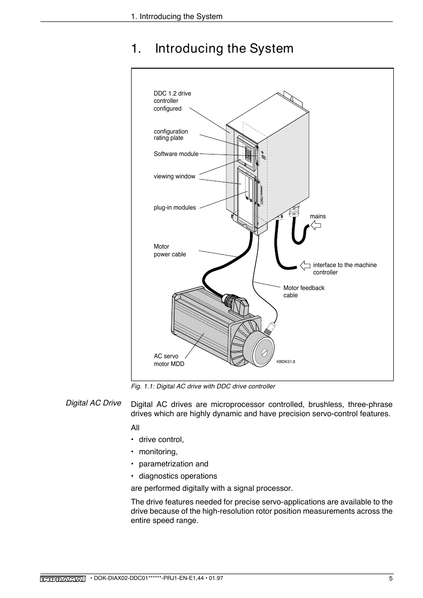
1. Intrroducing the System 1. Introducing the System A1 A2 DDC 1.2 drive controller configured configuration rating plate Software module viewing window plug-in modules Motor power cable mains interface to the machine controller Motor feedback cable AC servo motor MDD KBDKS1.8 Fig. 1.1: Digital AC drive with DDC drive controller Digital AC Drive Digital AC drives are microprocessor controlled, brushless, three-phrase drives which are highly dynamic and have precision servo-control features. All • drive control, • monitoring, • parametrization and • diagnostics operations are performed digitally with a signal processor. The drive features needed for precise servo-applications are available to the drive because of the high-resolution rotor position measurements across the entire speed range. • DOK-DIAX02-DDC01******-PRJ1-EN-E1,44 • 01.97 5
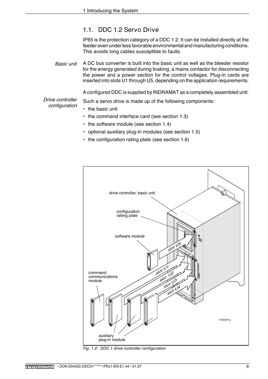
1.Introducing the System 1.1. DDC 1.2 Servo Drive IP65 is the protection category of a DDC 1.2. It can be installed directly at the feeder even under less favorable environmental and manufacturing conditions. This avoids long cables susceptible to faults. Basic unit A DC bus converter is built into the basic unit as well as the bleeder resistor for the energy generated during braking, a mains contactor for disconnecting the power and a power section for the control voltages. Plug-in cards are inserted into slots U1 through U5, depending on the application requirements. A configured DDC is supplied by INDRAMAT as a completely assembled unit. Drive controller configuration Such a servo drive is made up of the following components: • the basic unit • the command interface card (see section 1.3) • the software module (see section 1.4) • optional auxiliary plug-in modules (see section 1.5) • the configuration rating plate (see section 1.6) drive controller, basic unit configuration ratiing plate software module command communications module A1 A2 slot U5 slot U1 slot U2 slot U3 slot U4 auxiliary plug-in module Fig. 1.2: DDC 1 drive controller configuration PZDKSProj • DOK-DIAX02-DDC01******-PRJ1-EN-E1,44 • 01.97 6
1. Introducing the System 1.2. Functional Performance Features Protection Category IP 65: • space-saving installation, without a control cabinet, directly at the feeder • elimination of long connections between motor and drive which are susceptible to interference Power shutoff via integrated protection system in DDC: • power supply isolated by a contactor built into the unit • direct connection to 220V three-phase power source • a longer lifespan due to currentless switching Integral DC bus dynamic braking: • If trouble is encountered in the electronic circuitry of the drive, the drive can be decelerated and stopped with an integral dynamic brake system. Inrush current limit: • The inrush current does not need to be considered when selecting fuses or circuit breakers for the input power. Flexibility for specific applications: • The functions implemented on the drive can be matched to the given application by installing various plug-in modules in the servo drive. Motor holding brake: • Control and monitoring of the holding brake of the motor is integrated inside the servo drive unit. Programmable error reactions: • In the event of power, drive, or system faults, the drive performs the programmed error reaction. Easy to service: • Signal cables are connected via screw terminals. • Extensive diagnostics via alphanumeric display. • DOK-DIAX02-DDC01******-PRJ1-EN-E1,44 • 01.97 7
1. Introducing the System 1.3. Command Interface Card Depending upon type, the command interface module is either the interface to the NC control unit or a positioning control unit with interfaces to the hand terminal or the NC control unit of the machine. The following command interface cards are available: • SERCOS interface, type: DSS 1.1, DSS 1.3 • ANALOG interface with incremental encoder emulator, type: DAE 1.1 • ANALOG interface with absolute encoder emulator, type: DAA 1.1 • Positioning module, type: DLC 1.1 SERCOS interface Type: DSS 1.1, DSS 1.3 ANALOG interface with incremental encoder emulator ANALOG interface with absolute encoder emulator Single-axis positioning module The "SERCOS interface DSS" card allows the digital drives to be operated with SERCOS interface-compatible controllers via optical fiber cables. The interface also has inputs for evaluating reference switches, position limit switches and sensors. Type: DAE 1.1 The "ANALOG interface with incremental encoder emulator" card permits the intelligent digital AC servo drive to be operated with conventional controllers via an analog interface. It also contains control inputs and signal outputs for communication with attached controllers, and it outputs incremental encoder signals to be used as an actual position value. Type: DAA 1.1 The "ANALOG interface with absolute encoder emulator" card permits the intelligent digital AC servo drive to be operated with conventional controllers via an analog interface. It also contains control inputs and signal outputs for communications with an attached controller and it outputs actual absolute position values in accordance with SSI standards (Synchronous Serial Inter- face). Type: DLC 1.1 The "single-axis positioning module" card upgrades the servo drive to perform stand-alone, single-axis position control. This card can be programmed with up to 3,000 program blocks. Each program block defines a sequence of movements, a specific condition of the inputs to be monitored, or the outputs to be set. • DOK-DIAX02-DDC01******-PRJ1-EN-E1,44 • 01.97 8
分享到:
收藏