AAMToolbox: A Shape and
Appearance Modelling Toolbox for
Matlab
User Guide
Dr. A. I. Hanna
2007
aih@cmp.uea.ac.uk
Dr. A. I. Hanna
Page 1
16/11/2007
�
Table of Contents
Installing the software................................................................................................................ 4
Getting Started........................................................................................................................... 5
Overview of Toolbox.................................................................................................................. 6
Image Processing Tool.............................................................................................................. 8
Selecting images ................................................................................................................... 8
Resolution ............................................................................................................................. 8
Crop and Select..................................................................................................................... 8
Template Editor Tool ................................................................................................................. 9
Importing Templates.............................................................................................................. 9
New Templates ................................................................................................................... 10
Choosing Primary Points..................................................................................................... 10
Point Connectivity (Drawing Lines or edges) ...................................................................... 10
Saving the Point Model Template ....................................................................................... 11
Global Point Model Editing.................................................................................................. 11
New Project Tool ..................................................................................................................... 12
Making Augmented Projects.................................................................................................... 13
Importing Group Means........................................................................................................... 15
Choose Template Tool ............................................................................................................ 15
Point Model Editor Tool ........................................................................................................... 15
Moving Points...................................................................................................................... 16
Smoothing Points ................................................................................................................ 16
Other functions .................................................................................................................... 17
Automatic Placement Tool....................................................................................................... 17
Segmentation Fitting ........................................................................................................... 17
Subset Fitting ...................................................................................................................... 19
Likelihood Fitting ................................................................................................................. 19
Set Picker Tool ........................................................................................................................ 19
Modelling Subsets in Context.............................................................................................. 21
Select Images...................................................................................................................... 21
View Stats Model (PDM Walk) Tool ........................................................................................ 22
Shape Space Tool ................................................................................................................... 23
Creating Figures for Papers .................................................................................................... 28
Updating existing templates and point models........................................................................ 32
Conversion between old and new point model templates......... Error! Bookmark not defined.
Comments ............................................................................................................................... 33
Allometry model – the Mathematics ........................................................................................ 33
Contact Information: ................................................................................................................ 36
Dr. A. I. Hanna
Page 2
16/11/2007
�
Table of Figures
Figure 1 Computational Biology Download Page
Figure 2 Setting the path
Figure 3 Directory structure used by the Shape Model toolbox.
Figure 4 First look
Figure 5 Image processing toolbox
Figure 6 Cropping the image
Figure 7 Template Editor before and after loading (or creating) a template
Figure 8 Smoothing secondaries
Figure 9 Adding edges between points
1
1
1
1
1
Error! Bookmark not defined.
9
1
1
Dr. A. I. Hanna
Page 3
16/11/2007
�
now
copy
the
copied
section
for
(please see
Installing the software
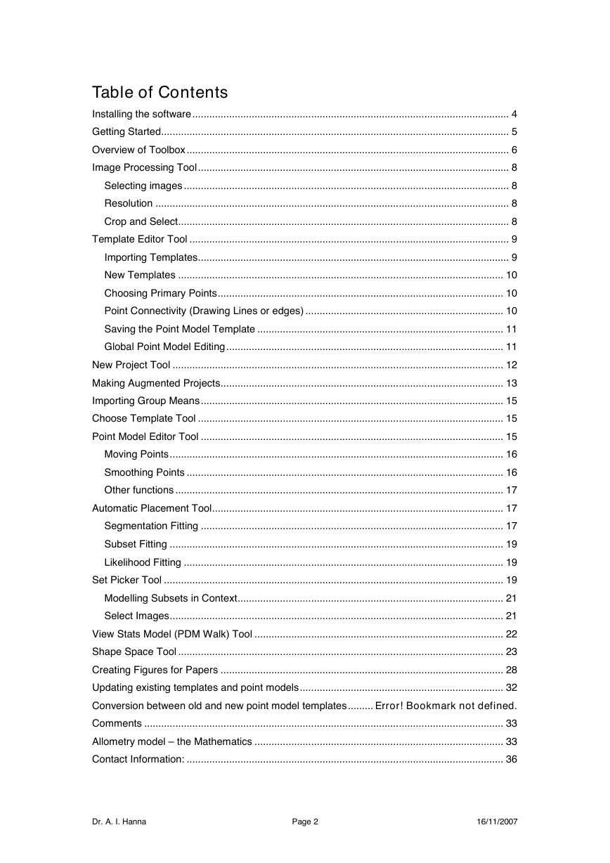
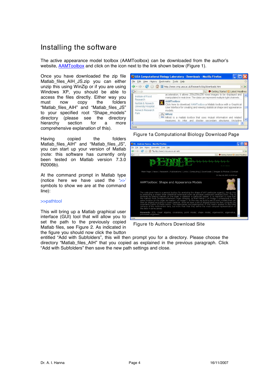
The active appearance model toolbox (AAMToolbox) can be downloaded from the author’s
website, AAMToolbox and click on the icon next to the link shown below (Figure 1).
Once you have downloaded the zip file
Matlab_files_AIH_JS.zip you can either
unzip this using WinZip or if you are using
Windows XP, you should be able to
access the files directly. Either way you
must
folders
“Matlab_files_AIH” and “Matlab_files_JS”
to your specified root “Shape_models”
the directory
directory
hierarchy
a more
comprehensive explanation of this).
Having
folders
Matlab_files_AIH” and “Matlab_files_JS”,
you can start up your version of Matlab
(note: this software has currently only
been
tested on Matlab version 7.3.0
R2006b).
At the command prompt in Matlab type
(notice here we have used
‘>>’
symbols to show we are at the command
line):
>>pathtool
This will bring up a Matlab graphical user
interface (GUI) tool that will allow you to
set the path to the previously copied
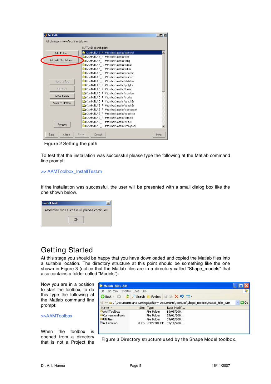
Matlab files, see Figure 2. As indicated in
the figure you should now click the button
entitled “Add with Subfolders”, this will then prompt you for a directory. Please choose the
directory “Matlab_files_AIH” that you copied as explained in the previous paragraph. Click
“Add with Subfolders” then save the new path settings and close.
Figure 1b Authors Download Site
the
Figure 1a Computational Biology Download Page
the
Dr. A. I. Hanna
Page 4
16/11/2007
�
Figure 2 Setting the path
To test that the installation was successful please type the following at the Matlab command
line prompt:
>> AAMToolbox_InstallTest.m
If the installation was successful, the user will be presented with a small dialog box like the
one shown below.
Getting Started
At this stage you should be happy that you have downloaded and copied the Matlab files into
a suitable location. The directory structure at this point should be something like the one
shown in Figure 3 (notice that the Matlab files are in a directory called “Shape_models” that
also contains a folder called “Models”):
Now you are in a position
to start the toolbox, to do
this type the following at
the Matlab command line
prompt:
>>AAMToolbox
is
When
opened from a directory
that is not a Project the
Figure 3 Directory structure used by the Shape Model toolbox.
the
toolbox
Dr. A. I. Hanna
Page 5
16/11/2007
�
Current Template and Sample image axes are empty and the Current Working Project
indicates ‘No Project Selected’
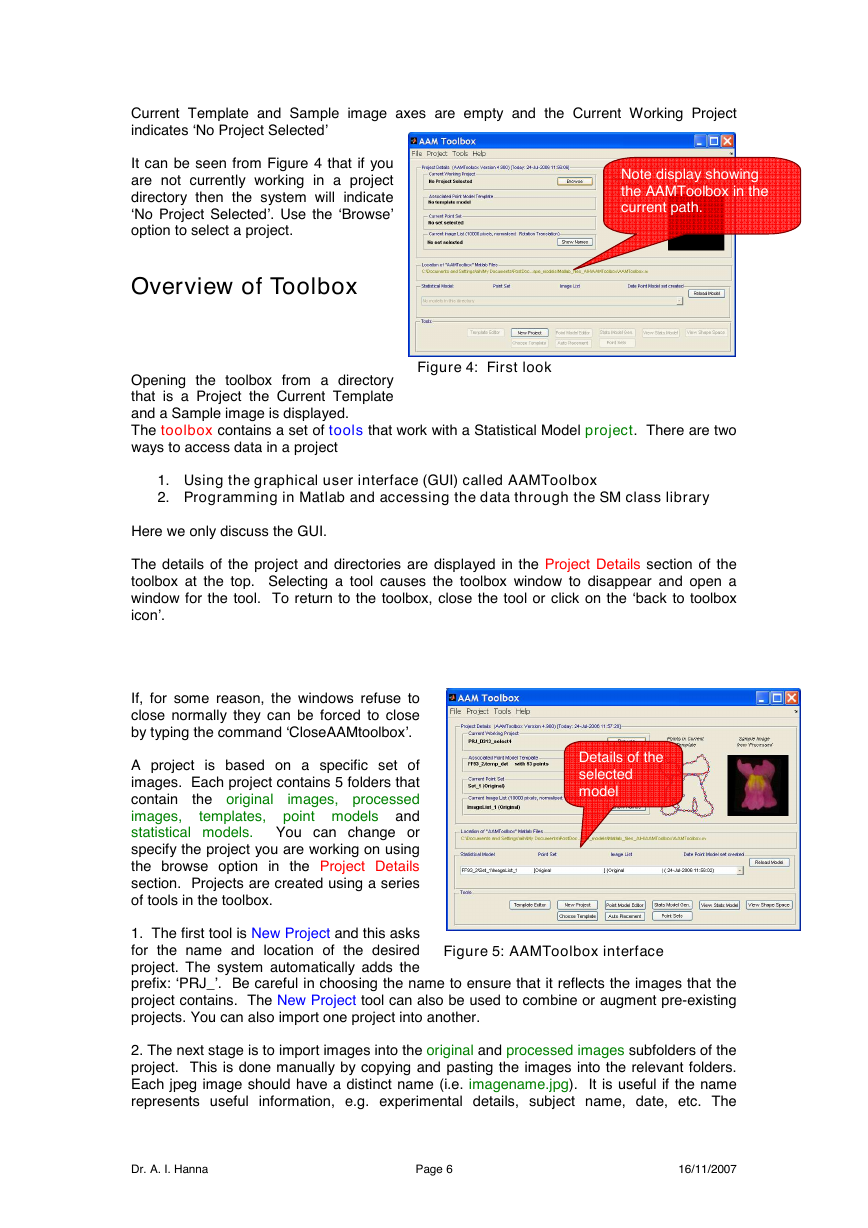
It can be seen from Figure 4 that if you
are not currently working in a project
directory then the system will indicate
‘No Project Selected’. Use the ‘Browse’
option to select a project.
Note display showing
the AAMToolbox in the
current path.
Overview of Toolbox
Opening the toolbox from a directory
that is a Project the Current Template
and a Sample image is displayed.
The toolbox contains a set of tools that work with a Statistical Model project. There are two
ways to access data in a project
Figure 4: First look
1. Using the graphical user interface (GUI) called AAMToolbox
2. Programming in Matlab and accessing the data through the SM class library
Here we only discuss the GUI.
The details of the project and directories are displayed in the Project Details section of the
toolbox at the top. Selecting a tool causes the toolbox window to disappear and open a
window for the tool. To return to the toolbox, close the tool or click on the ‘back to toolbox
icon’.
If, for some reason, the windows refuse to
close normally they can be forced to close
by typing the command ‘CloseAAMtoolbox’.
A project is based on a specific set of
images. Each project contains 5 folders that
the original
contain
images, processed
images,
templates, point models and
statistical models. You can change or
specify the project you are working on using
the browse option in the Project Details
section. Projects are created using a series
of tools in the toolbox.
1. The first tool is New Project and this asks
for the name and location of the desired
project. The system automatically adds the
prefix: ‘PRJ_’. Be careful in choosing the name to ensure that it reflects the images that the
project contains. The New Project tool can also be used to combine or augment pre-existing
projects. You can also import one project into another.
2. The next stage is to import images into the original and processed images subfolders of the
project. This is done manually by copying and pasting the images into the relevant folders.
Each jpeg image should have a distinct name (i.e. imagename.jpg). It is useful if the name
represents useful information, e.g. experimental details, subject name, date, etc. The
Details of the
selected
model
Figure 5: AAMToolbox interface
Dr. A. I. Hanna
Page 6
16/11/2007
�
processed images should all have the same size in pixels (a convenient size is 800 pixels
wide). To help with processing, you can use the image processing tool. Note that if you
want to create an allometric model (one that does not normalise size), you need to untick the
scale box in the Procrustes section of the SMG (Statistical Model Generator) tool (see below).
3. You then need to import at least one template into the Templates folder of the project. This
can either be done manually by copying previous templates and pasting, or using the
template editor tool to browse the list of templates. If you do not have a template you will
need to create one using the template editor tool. Templates all have the suffix .temp_dat. (In
some cases a supplementary file with the suffix .edit_set will be created.)
Point Model
Place points defined by the
template into the correct
positions on every image
Stats Model Gen.
Generate statistical model
from multiple Point Models
View Stats Model
View the statistical model
generated from the Point
Models
Figure 6 Point models to Statistical models.
4. To start creating models (Point Models for each image and Statistical models derived from
multiple images) you need to assign one template from the Templates folder using the choose
template tool. This will create folders with the template name in PointModels and
StatisticalModels directories (i.e. Pointmodels/template_name). Thus all models based on
this template will carry the template_name as an identifier.
5. To define the positions of points in relation to the images there are two options.
A. Point models are created according to the template (selected previously, see
above). They are usual created manually using the Point Model Editor (PM_editor)
tool. Points are moved to the appropriate feature points in the image. A Point Model
is created for each image in the Cropped directory. The pm (point model) files are
stored
subfolder within PointModels directory.
(i.e.pointmodels/template_name/imagename.pm). Note that these are not exclusive
– you could first use Autoplacement and then check the points manually using
PM_editor
template-name
in
the
B. For some image shapes (e.g. leaves), you can automatically place points on your
images using the Autoplacement tool. When you invoke this tool, it will ask you
whether you want to place points through segmentation, warp all points according to
a subset of points, or fit using a probabilistic model based on a subset of points. In
the segmentation option you will be asked to specify the type of image you want to
segment (e.g. petals, leaves etc) and will then create a set of binary images in a
processed images/binary subfolder. You then click on a few key points and draft
point models are created.
7. When Point Models have been created for each image you need to consider which points
to use for your statistical point model. Models associated with each set are stored in separate
subfolders of the StatisticalModels folder. By default all points of the template are used to
create the statistical point model. This is stored in a subfolder called Set_1 located in
StatisticalModels/ template_name. You may also want to select a subset of points. This is
done using Point Sets tool that allows you to choose the subset of points to be used. The
point sub-set information is stored in a newly created folder called Set_2 (further subsets will
be named consecutively) located in StatisticalModels/ template_name. You can also give the
selection of points a logical name and this will be displayed in the project details area.
8. To build a statistical model you now use the SMG (Statistical Model Generator) tool. Using
this, you first need to choose the images that should be included in the statistical models. By
default all images in processed images will be used. This will create a subfolder called
ImageList_1 in StatisticalModels/ template_name /Set_1. You may also want to select a
subset of images. This is done using a drop-down menu within the SMG tool. This allows
Dr. A. I. Hanna
Page 7
16/11/2007
�
you to choose the subset of images to be used and when this is complete, the image set
information is stored in a newly created folder called ImageList_2 (further subsets will be
named consecutively) located in StatisticalModels/ template_name /Set_1. You can also give
the selection of images a logical name and this will be displayed in the project details area.
Within SMG you can also generate a combined shape and appearance model. (You can also
generate appearance models based on treating each triangle as a patch or using wavelets: to
be done).
9. Statistical models can be displayed using the View Stats Model tool. Within this you can
A. Examine how each principal component affects shape and appearance
B. Make movies of the shape and appearance changes
C. Import images to modify the mean appearance
D. Evaluate how well an image is created by the model compares to the original image
E. Examine the effect of quantising shape and appearance space
10. Statistical models can be viewed in shape space 2 or 3D shape space using the View
Shape Space tool.
the
images from
Image Processing Tool
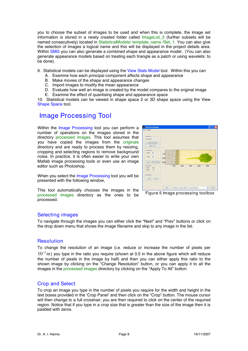
Within the Image Processing tool you can perform a
number of operations on the images stored in the
directory processed images. This tool assumes that
you have copied
the originals
directory and are ready to process them by resizing,
cropping and selecting regions to remove background
noise. In practice, it is often easier to write your own
Matlab image processing tools or even use an image
editor such as Photoshop.
When you select the Image Processing tool you will be
presented with the following window,
This tool automatically chooses the images in the
processed
to be
processed.
images directory as
the ones
Figure 5 Image processing toolbox
Selecting images
To navigate through the images you can either click the “Next” and “Prev” buttons or click on
the drop down menu that shows the image filename and skip to any image in the list.
Resolution
To change the resolution of an image (i.e. reduce or increase the number of pixels per
m210-
) you type in the ratio you require (shown at 0.5 in the above figure which will reduce
the number of pixels in the image by half) and then you can either apply this ratio to the
shown image by clicking on the “Change Resolution” button, or you can apply it to all the
images in the processed images directory by clicking on the “Apply To All” button.
Crop and Select
To crop an image you type in the number of pixels you require for the width and height in the
text boxes provided in the ‘Crop Panel’ and then click on the “Crop” button. The mouse cursor
will then change to a full crosshair; you are then required to click on the center of the required
region. Notice that if you type in a crop size that is greater than the size of the image then it is
padded with zeros.
Dr. A. I. Hanna
Page 8
16/11/2007
�




 2023年江西萍乡中考道德与法治真题及答案.doc
 2012年重庆南川中考生物真题及答案.doc
 2013年江西师范大学地理学综合及文艺理论基础考研真题.doc
 2020年四川甘孜小升初语文真题及答案I卷.doc
 2020年注册岩土工程师专业基础考试真题及答案.doc
 2023-2024学年福建省厦门市九年级上学期数学月考试题及答案.doc
 2021-2022学年辽宁省沈阳市大东区九年级上学期语文期末试题及答案.doc
 2022-2023学年北京东城区初三第一学期物理期末试卷及答案.doc
 2018上半年江西教师资格初中地理学科知识与教学能力真题及答案.doc
 2012年河北国家公务员申论考试真题及答案-省级.doc
 2020-2021学年江苏省扬州市江都区邵樊片九年级上学期数学第一次质量检测试题及答案.doc
 2022下半年黑龙江教师资格证中学综合素质真题及答案.doc