Preface
About this Book
How the Book is Organized
Case Studies
To See How To:
Go To:
Model
page 15
page 17
page 20
page 22
Analysis
page 26
page 26
Results
page 27
page 28
To See How To:
Go To:
Model
page 86
page 88
page 91
Analysis
page 97
Results
page 98
To See How To:
Go To:
Model
page 162
page 165
Analysis
page 166
Results
page 169
Other Books
About MSC
Technical Support
Personal Information
System Information
Product Information
Telephone and Fax:
E-mail:
MSC Web Site
MSC Institute of Technology
How to Register
MSC Partners
CAD Partners
Hardware Partners
Analysis Partners
Documentation Conventions
Chapter 1: Introduction
Virtual Product Development
VPD and Simulation Software
Interfacing with CAD and Vertical Applications
A First Look at Patran
Task Interface
Tools and Applications
Data Management
A Link to Other Software
Profile of a Simulation Project
Simulation Tasks and Patran
Simulating a Product Design
Turning Product Designs into Geometry Models
Meshing and Creating Elements
Modeling Materials
Simulating Forces and Loads
Analyzing the Model with Environmental Loads
Selecting an Analysis Code
Tailoring the Model for a Selected Analysis Code
Running a Finite Element Analysis
Compiling the Analysis Results
Visualizing Numerical Results
The Sequence of Tasks
A Case Study of an Annular Plate
Problem Description
Figure 1-1 Representation of the Annular Plate
Table 1-1 Dimensions and Properties of the Annular Plate
Conceptual Model
Figure 1-2 Patran Finite Element model of Annular Plate
Theoretical Solution
Case Study Task Outline
Figure 1-3 Case Study Task Map
Analysis Procedure
Setup the Analysis Project
Build the Geometry
Create the Finite Elements
Equivalencing the Mesh
Model the Materials
Define Element Properties
Simulate the Loads and Boundary Conditions (LBC)
Create MSC Nastran Input File
Retrieve the Analysis Results
Results Postprocessing
Chapter 2: Fundamentals
Starting and Exiting Patran
A Tour of the Patran Interface
How to Get Things Done
Working with Viewports
2. Click and drag the viewport to a new location.
3. Window machines allow for double clicking to fit the graphics window.
2. When a two-headed arrow appears, click and drag the viewport to the desired size.
2. Enter a name for the new viewport in the New Viewport Name textbox, and click Apply.
The Menu Bar
File
Group
Viewport
Viewing
Viewing Size and Positions on the Toolbar
More About Viewing Rotation
Display
Preferences
Tools
Using Lists
Help
Application Buttons and Application Forms
Application
Function
Application Forms
The Toolbar
System Functions
Mouse Functions
Icon Name
UNIX Icon
Function
Viewing Functions
Icon Name
UNIX Icon
Function
Icon Name
UNIX Icon
Function
Display Functions
Icon Name
UNIX Icon
Function
Icon Name
UNIX Icon
Function
Home (Windows only)
Heartbeat
Command Line and History List Area
Picking and Selecting
Select Menus
Icon
Function
Multilevel Select Menus
Appearance of the Select Menu
2. Click and drag the menu to a new location.
2. To switch to a horizontal set of icons, click and drag the Select menu to the toolbar area or to the History/Command Line area.
Picking an Entity off the Screen
Enclosing Entities
2. First move the cursor into the application form databox and click.
3. Next move the cursor into the viewport. Click once to define the first vertice of the polygon.
2. Click and drag the cursor arrow to define an enclosing rectangle.
Selecting Individual Entities
2. Point the cursor arrow at the desired object and click.
2. Click in the application form databox and then move the cursor into the viewport. Point the cursor at the desired object and click.
Clearing Selected Entities
Selecting All Entities
Changing the Picking Operation
2. Click on the Show Picking Icons checkbox.
3. Quit and restart Patran.
4. Resume the Application that brings up your Select menu.
5. Click on one of the other Picking Operation icons to change the Picking mode.
Chapter 3: The Database
Creating a Database
2. Specify the filename for the new Patran database.
3. Select the directory in which the database will reside (located at the bottom of the form).
Specifying Model Parameters
Global Model Tolerance Definition
Analysis Code and Analysis Type
2. Use the Analysis Type drop-down menu to assign the type of analysis.
Importing CAD Models
2. On the Object drop-down menu, select Model.
3. Specify a Source from the Source drop-down menu.
4. Click Apply.
Import Options
Chapter 4: Geometry Modeling
Overview of Geometry
Options for Starting the Geometry Model
Model Building Tasks
Basic Concepts and Definitions
Parametric Space and Connectivity
Patran’s Mapping Functions Translate Between Parametric and XYZ Space
Figure 4-1 Mapping a surface from parametric space to global XYZ space
Connectivity
Figure 4-2 Two possible connectivities for a surface
Geometric Entities
Points
Curves
Surfaces
Solids
Planes and Vectors
Coordinate Systems and Frames
Figure 4-3 Coordinate Systems
Subentities
Congruency
Creating Geometry
Using the Geometry Application Form
2. Select an Action/Object/Method combination from the drop-down menus at the top of the Geometry application form.
Actions
Objects
Methods
Sample Geometry Form
Creating Trimmed Surfaces
Creating B-Rep Solids
Working with Imported CAD Models
Remove Excess Detail
Add Missing Surfaces
Repair Incomplete Entities
Checking the Geometry
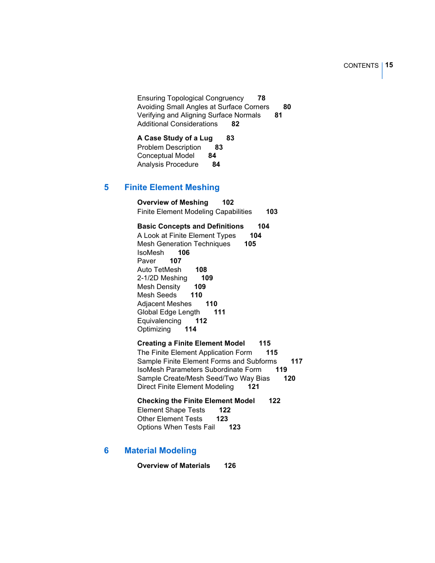
Ensuring Topological Congruency
Figure 4-4 Congruent geometry example
Finding Incongruencies
Correcting Incongruencies
Figure 4-5 Noncongruent geometry with missing vertices
Avoiding Small Angles at Surface Corners
Figure 4-6 Surfaces with and without sharp corners
Verifying and Aligning Surface Normals
Additional Considerations
A Case Study of a Lug
Problem Description
Figure 4-7 Loads on the Lug
Table 4-1 Properties of the Lug
Conceptual Model
Analysis Procedure
Setup the Analysis Project
Import the Geometry
Create a New Coordinate System
Create the Finite Elements
Model the Materials
Define Element Properties
Create a PCL Function Representing the Loading Condition
Simulate the Loads and Boundary Conditions (LBC)
Run MD Nastran
Results Postprocessing
Chapter 5: Finite Element Meshing
Overview of Meshing
Figure 5-1 A geometry model versus a finite element representation
Finite Element Modeling Capabilities
Basic Concepts and Definitions
A Look at Finite Element Types
Mesh Generation Techniques
IsoMesh
Figure 5-2 Example of solid IsoMesh
Paver
Figure 5-3 Example of Paver mesh technique
Auto TetMesh
Figure 5-4 Auto TetMesh technique
2-1/2D Meshing
Mesh Density
Mesh Seeds
Figure 5-5 A mesh transition using mesh seeds
Adjacent Meshes
Figure 5-6 Mesh path examples
Global Edge Length
Equivalencing
Optimizing
Figure 5-7 A Sparse, Symmetric Matrix
Creating a Finite Element Model
The Finite Element Application Form
2. Select an Action, Object, and Type using the drop-down menus at the top of the form.
Actions
Objects
Types
Sample Finite Element Forms and Subforms
Create/Mesh/Solid Form
IsoMesh Parameters Subordinate Form
Sample Create/Mesh Seed/Two Way Bias
Direct Finite Element Modeling
Checking the Finite Element Model
2. Select the corresponding Object and Method for checking an aspect of your finite element mesh.
Element Shape Tests
Other Element Tests
Options When Tests Fail
Remesh the Model
2. Re-create the mesh by selecting from the Create/Mesh family of options described above.
Repair Individual Elements
Check your Tolerance
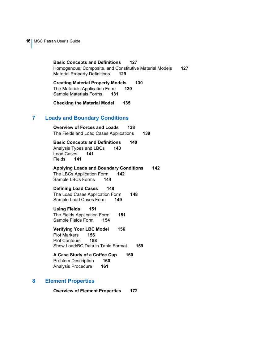
Chapter 6: Material Modeling
Overview of Materials
Basic Concepts and Definitions
Homogenous, Composite, and Constitutive Material Models
Homogenous Material Types
Type (Object)
Structural Characteristics
Composite Material Types
Method
Variations
Algorithm
Intended Application
Constitutive Models
Material Property Definitions
Material Property Fields
Creating Material Property Models
The Materials Application Form
2. Select an Action, Object, and Method from the drop-down menus at the top of the form.
Actions
Objects
Methods
Sample Materials Forms
Sample Manual Input Form
Sample Input Options Subform
Sample Constitutive Model Status form
Checking the Material Model
2. With the Method set to Tabular, select one of your material models from the Existing Materials listbox.
3. Select either Show Material Stiffness or Show Material Compliance to display the stiffness or compliance matrix.
Chapter 7: Loads and Boundary Conditions
Overview of Forces and Loads
Figure 7-1 Model with point load and displacement boundary conditions
The Fields and Load Cases Applications
Figure 7-2 Three LBCs-related applications
Basic Concepts and Definitions
Analysis Types and LBCs
Structural Loads and Boundary Conditions
Thermal Loads and Boundary Conditions
Fluid Dynamics Loads and Boundary Conditions
Load Cases
Fields
Applying Loads and Boundary Conditions
The LBCs Application Form
2. Choose an action, object, and type combination from the pop-up menus.
Actions
Objects
Analysis Type
LBC Object (Set Type)
Types
Sample LBCs Forms
Sample Loads/BCs Input Form
Widgets
Sample Input Data Subform
Widgets
Sample Select Application Region Subform
Widgets
Defining Load Cases
The Load Cases Application Form
2. Select an Action from the top of the application form.
Actions
Sample Load Cases Form
Widgets
Using Fields
The Fields Application Form
2. From the drop-down menus, select an Action, Object, and Method.
Actions
Objects
Field Type
Description
Methods
Field Type
Description
Sample Fields Form
Widgets
Verifying Your LBC Model
Plot Markers
Figure 7-3 Examples of Plot Markers for LBCs
Figure 7-4 Display menu for Loads/BCs/El.Props
Plot Contours
2. From the Object drop-down menu, select the load/boundary condition you wish to plot.
Show Load/BC Data in Table Format
Figure 7-5 Numerical display of LBCs data from Show Tabular action
A Case Study of a Coffee Cup
Problem Description
Analysis Procedure
Setup the Analysis Project
Import the Geometry
Plot the Loads and Boundary Conditions (LBC)
Assign a New Pressure Load to the Model
Create MSC Nastran Input File
Retrieve the Analysis Results
Results Postprocessing
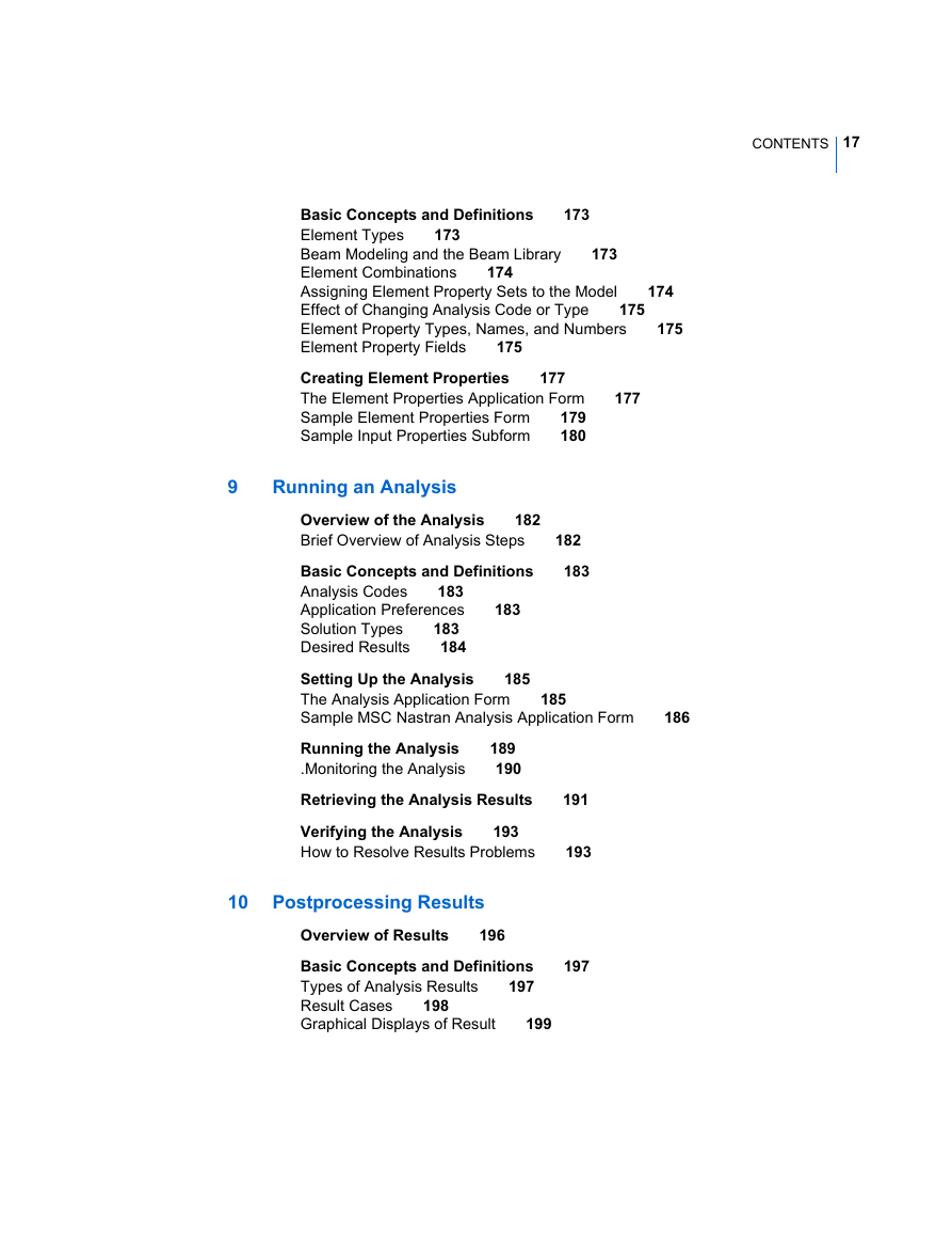
Chapter 8: Element Properties
Overview of Element Properties
Basic Concepts and Definitions
Element Types
Dimension
Type
Beam Modeling and the Beam Library
Element Combinations
Dimension
Type
Option 1
Option 2
Topology
Assigning Element Property Sets to the Model
Effect of Changing Analysis Code or Type
Element Property Types, Names, and Numbers
Element Property Fields
Viewing Element Property Sets
Show/Marker Plot
Show/Scalar Plot
Show/Tabular Plot
Creating Element Properties
The Element Properties Application Form
2. Select an Action, Dimension, and Type combination at the top of the application form.
Actions
Dimensions and Types
Dimension
Type
Sample Element Properties Form
Sample Input Properties Subform
Chapter 9: Running an Analysis
Overview of the Analysis
Brief Overview of Analysis Steps
Basic Concepts and Definitions
Analysis Codes
Application Preferences
Solution Types
Desired Results
Setting Up the Analysis
The Analysis Application Form
2. Select an Action, Object, and Method from the top of the application form.
3. Check the analysis code and analysis type.
Actions
Objects
Methods
Sample MSC Nastran Analysis Application Form
Sample Analysis Application form
Sample MSC Nastran Solution Type Subform
Running the Analysis
2. Select the Apply button.
2. Click on the Apply button
.Monitoring the Analysis
Retrieving the Analysis Results
2. Click on the Select Results File unfold box.
Actions
Objects
Methods
Verifying the Analysis
How to Resolve Results Problems
Chapter 10: Postprocessing Results
Overview of Results
Basic Concepts and Definitions
Types of Analysis Results
Figure 10-1 Color fringe plot of scalar result values
Figure 10-2 Deformed shape plot of vector quantities
Result Cases
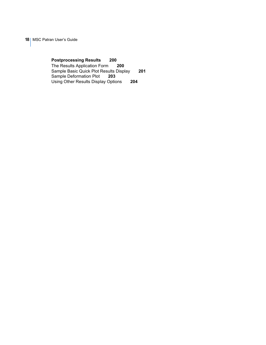
Graphical Displays of Result
Postprocessing Results
The Results Application Form
2. Select an Action and Object from the drop-down menus at the top of the form.
Actions
Objects
Plot
Description
Sample Basic Quick Plot Results Display
Sample Deformation Plot
2. Select a Results Case from this listbox.
3. Select a result associated with the Results Case from this listbox.
4. Press the Apply button on the bottom of the form.
Using Other Results Display Options
Results Options
Index


 2023年江西萍乡中考道德与法治真题及答案.doc
 2012年重庆南川中考生物真题及答案.doc
 2013年江西师范大学地理学综合及文艺理论基础考研真题.doc
 2020年四川甘孜小升初语文真题及答案I卷.doc
 2020年注册岩土工程师专业基础考试真题及答案.doc
 2023-2024学年福建省厦门市九年级上学期数学月考试题及答案.doc
 2021-2022学年辽宁省沈阳市大东区九年级上学期语文期末试题及答案.doc
 2022-2023学年北京东城区初三第一学期物理期末试卷及答案.doc
 2018上半年江西教师资格初中地理学科知识与教学能力真题及答案.doc
 2012年河北国家公务员申论考试真题及答案-省级.doc
 2020-2021学年江苏省扬州市江都区邵樊片九年级上学期数学第一次质量检测试题及答案.doc
 2022下半年黑龙江教师资格证中学综合素质真题及答案.doc