王金明:《 Verilog HDL 程序设计教程》
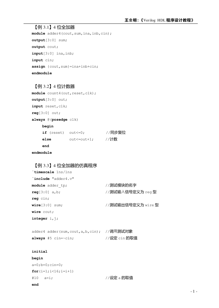
【例 3.1】4 位全加器
module adder4(cout,sum,ina,inb,cin);
output[3:0] sum;
output cout;
input[3:0] ina,inb;
input cin;
assign {cout,sum}=ina+inb+cin;
endmodule
【例 3.2】4 位计数器
module count4(out,reset,clk);
output[3:0] out;
input reset,clk;
reg[3:0] out;
always @(posedge clk)
begin
if (reset) out<=0; //同步复位
else
out<=out+1;
//计数
end
endmodule
【例 3.3】4 位全加器的仿真程序
`timescale 1ns/1ns
`include "adder4.v"
module adder_tp;
reg[3:0] a,b;
reg cin;
wire[3:0] sum;
wire cout;
integer i,j;
adder4 adder(sum,cout,a,b,cin); //调用测试对象
always #5 cin=~cin;
initial
begin
a=0;b=0;cin=0;
for(i=1;i<16;i=i+1)
#10 a=i;
end
//设定 a 的取值
//测试模块的名字
//测试输入信号定义为 reg 型
//测试输出信号定义为 wire 型
//设定 cin 的取值
- 1 -
�
程序文本
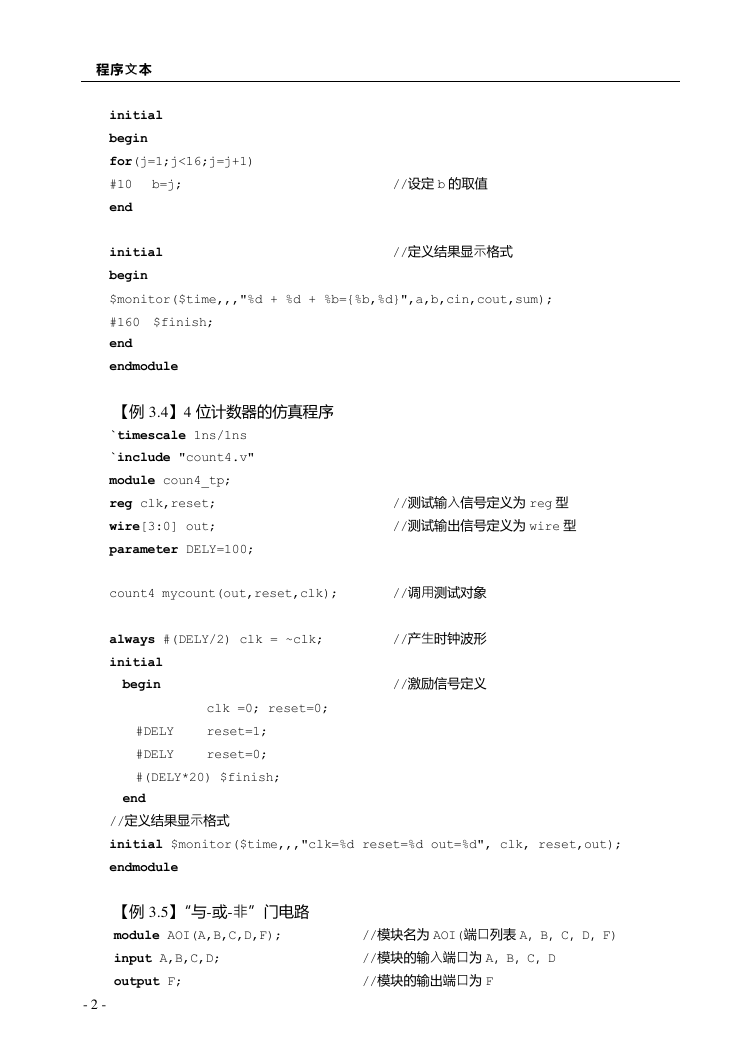
//设定 b 的取值
//定义结果显示格式
initial
begin
for(j=1;j<16;j=j+1)
#10 b=j;
end
initial
begin
$monitor($time,,,"%d + %d + %b={%b,%d}",a,b,cin,cout,sum);
#160 $finish;
end
endmodule
【例 3.4】4 位计数器的仿真程序
`timescale 1ns/1ns
`include "count4.v"
module coun4_tp;
reg clk,reset;
wire[3:0] out;
parameter DELY=100;
count4 mycount(out,reset,clk);
always #(DELY/2) clk = ~clk;
initial
//调用测试对象
//产生时钟波形
//测试输入信号定义为 reg 型
//测试输出信号定义为 wire 型
begin
clk =0; reset=0;
//激励信号定义
#DELY reset=1;
#DELY reset=0;
#(DELY*20) $finish;
end
//定义结果显示格式
initial $monitor($time,,,"clk=%d reset=%d out=%d", clk, reset,out);
endmodule
【例 3.5】“与-或-非”门电路
module AOI(A,B,C,D,F);
input A,B,C,D;
output F;
//模块名为 AOI(端口列表 A,B,C,D,F)
//模块的输入端口为 A,B,C,D
//模块的输出端口为 F
- 2 -
�
王金明:《 Verilog HDL 程序设计教程》
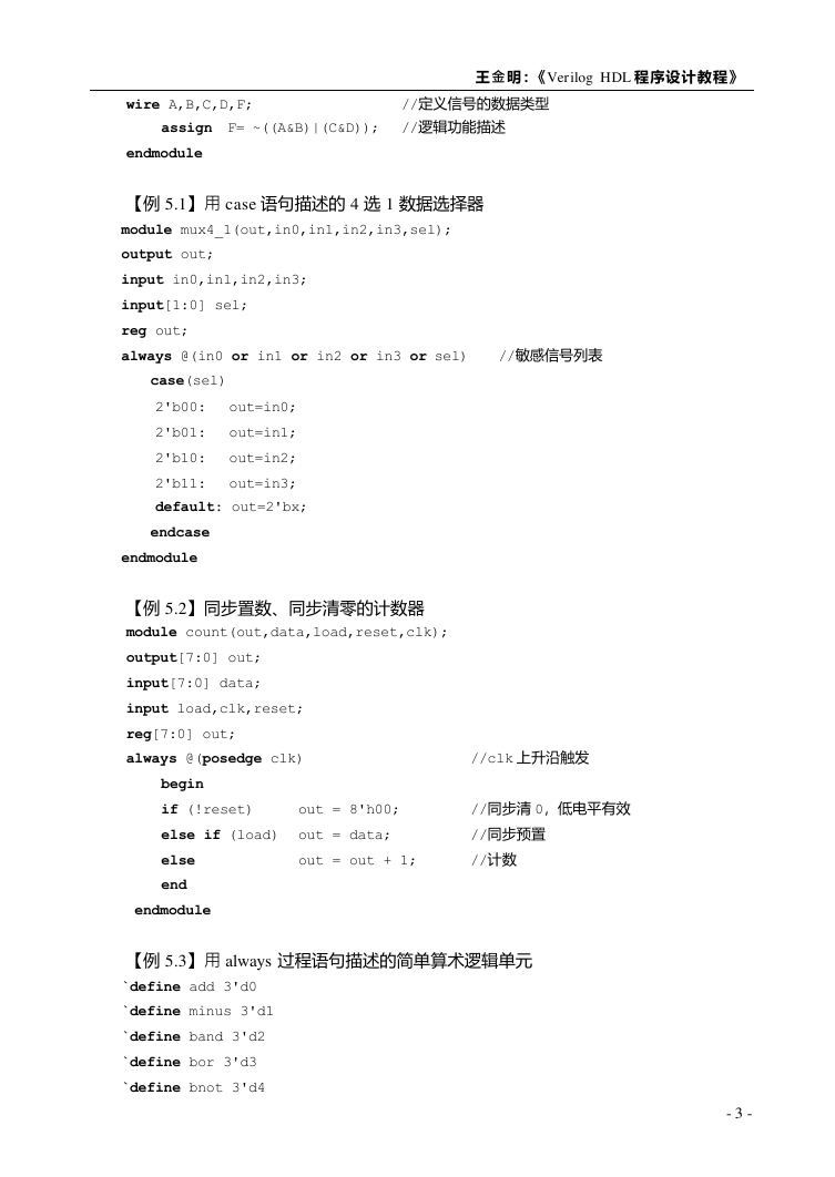
//定义信号的数据类型
wire A,B,C,D,F;
assign F= ~((A&B)|(C&D)); //逻辑功能描述
endmodule
【例 5.1】用 case 语句描述的 4 选 1 数据选择器
module mux4_1(out,in0,in1,in2,in3,sel);
output out;
input in0,in1,in2,in3;
input[1:0] sel;
reg out;
always @(in0 or in1 or in2 or in3 or sel) //敏感信号列表
case(sel)
2'b00: out=in0;
2'b01: out=in1;
2'b10: out=in2;
2'b11: out=in3;
default: out=2'bx;
endcase
endmodule
【例 5.2】同步置数、同步清零的计数器
module count(out,data,load,reset,clk);
output[7:0] out;
input[7:0] data;
input load,clk,reset;
reg[7:0] out;
always @(posedge clk)
begin
if (!reset)
out = 8'h00;
else if (load) out = data;
else
end
out = out + 1;
//clk 上升沿触发
//同步清 0,低电平有效
//同步预置
//计数
endmodule
【例 5.3】用 always 过程语句描述的简单算术逻辑单元
`define add 3'd0
`define minus 3'd1
`define band 3'd2
`define bor 3'd3
`define bnot 3'd4
- 3 -
�
程序文本
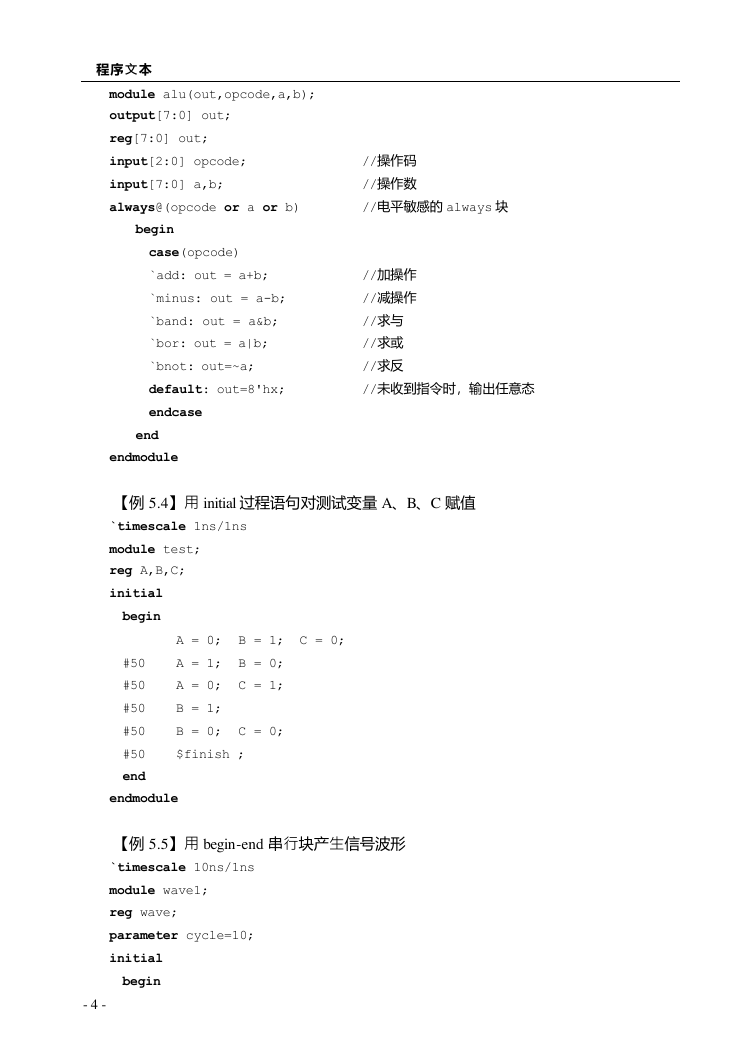
module alu(out,opcode,a,b);
output[7:0] out;
reg[7:0] out;
input[2:0] opcode;
input[7:0] a,b;
always@(opcode or a or b)
begin
//操作码
//操作数
//电平敏感的 always 块
case(opcode)
`add: out = a+b;
`minus: out = a-b;
`band: out = a&b;
`bor: out = a|b;
`bnot: out=~a;
default: out=8'hx;
endcase
end
//加操作
//减操作
//求与
//求或
//求反
//未收到指令时,输出任意态
endmodule
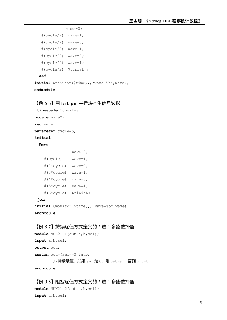
【例 5.4】用 initial 过程语句对测试变量 A、B、C 赋值
`timescale 1ns/1ns
module test;
reg A,B,C;
initial
begin
A = 0; B = 1; C = 0;
#50
#50
#50
#50
#50
end
endmodule
【例 5.5】用 begin-end 串行块产生信号波形
`timescale 10ns/1ns
module wave1;
reg wave;
parameter cycle=10;
initial
begin
A = 1; B = 0;
A = 0; C = 1;
B = 1;
B = 0; C = 0;
$finish ;
- 4 -
�
王金明:《 Verilog HDL 程序设计教程》
wave=0;
#(cycle/2) wave=1;
#(cycle/2) wave=0;
#(cycle/2) wave=1;
#(cycle/2) wave=0;
#(cycle/2) wave=1;
#(cycle/2) $finish ;
end
initial $monitor($time,,,"wave=%b",wave);
endmodule
【例 5.6】用 fork-join 并行块产生信号波形
`timescale 10ns/1ns
module wave2;
reg wave;
parameter cycle=5;
initial
fork
wave=0;
#(cycle) wave=1;
#(2*cycle) wave=0;
#(3*cycle) wave=1;
#(4*cycle) wave=0;
#(5*cycle) wave=1;
#(6*cycle) $finish;
join
initial $monitor($time,,,"wave=%b",wave);
endmodule
【例 5.7】持续赋值方式定义的 2 选 1 多路选择器
module MUX21_1(out,a,b,sel);
input a,b,sel;
output out;
assign out=(sel==0)?a:b;
endmodule
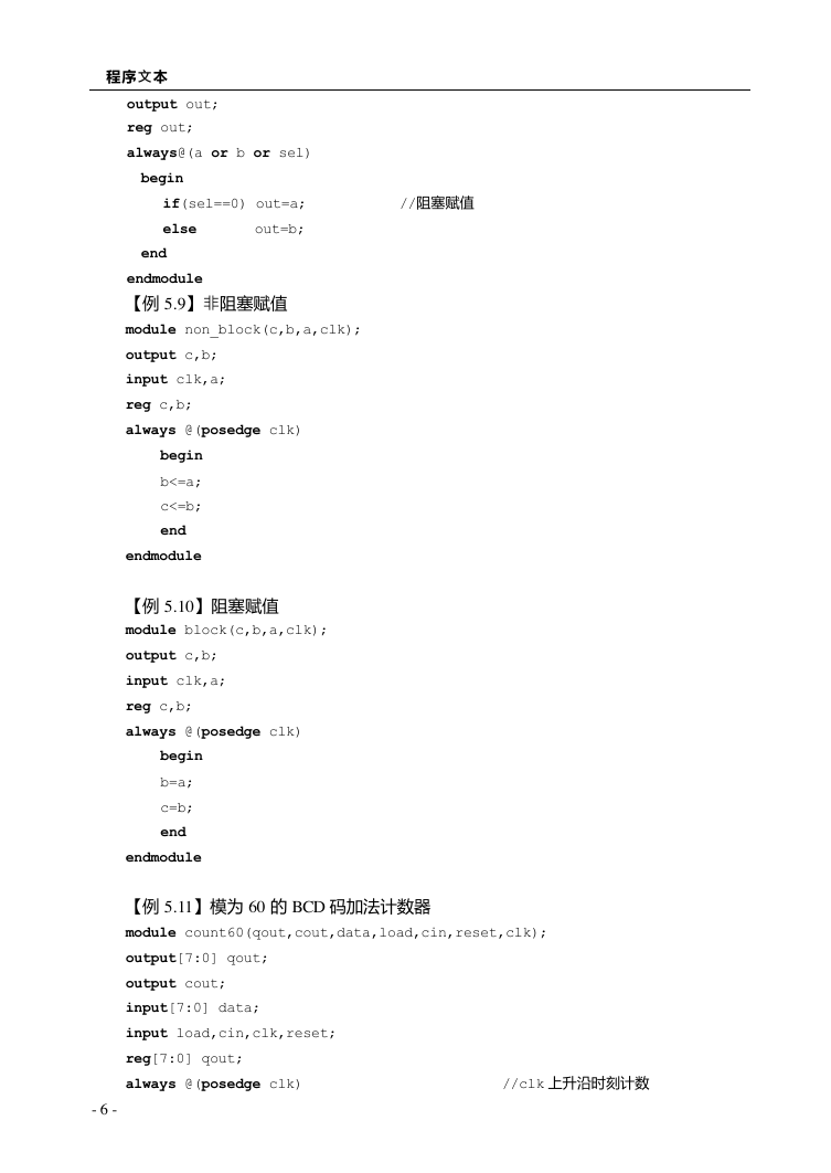
【例 5.8】阻塞赋值方式定义的 2 选 1 多路选择器
module MUX21_2(out,a,b,sel);
input a,b,sel;
//持续赋值,如果 sel 为 0,则 out=a ;否则 out=b
- 5 -
�
程序文本
end
//阻塞赋值
output out;
reg out;
always@(a or b or sel)
begin
if(sel==0) out=a;
else out=b;
end
endmodule
【例 5.9】非阻塞赋值
module non_block(c,b,a,clk);
output c,b;
input clk,a;
reg c,b;
always @(posedge clk)
begin
b<=a;
c<=b;
endmodule
【例 5.10】阻塞赋值
module block(c,b,a,clk);
output c,b;
input clk,a;
reg c,b;
always @(posedge clk)
begin
b=a;
c=b;
end
endmodule
【例 5.11】模为 60 的 BCD 码加法计数器
module count60(qout,cout,data,load,cin,reset,clk);
output[7:0] qout;
output cout;
input[7:0] data;
input load,cin,clk,reset;
reg[7:0] qout;
always @(posedge clk)
//clk 上升沿时刻计数
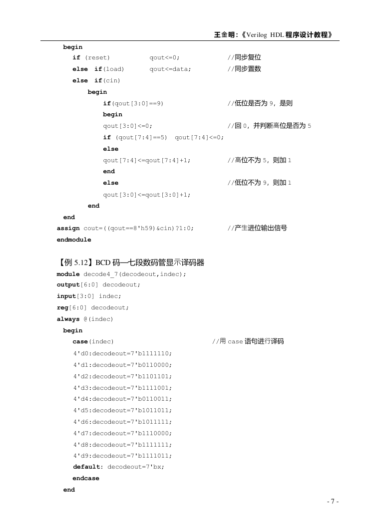
- 6 -
�
王金明:《 Verilog HDL 程序设计教程》
begin
if (reset)
else if(load)
else if(cin)
begin
qout<=0;
qout<=data;
//同步复位
//同步置数
//低位是否为 9,是则
//回 0,并判断高位是否为 5
if(qout[3:0]==9)
begin
qout[3:0]<=0;
if (qout[7:4]==5) qout[7:4]<=0;
else
qout[7:4]<=qout[7:4]+1;
end
else
qout[3:0]<=qout[3:0]+1;
//高位不为 5,则加 1
//低位不为 9,则加 1
end
end
assign cout=((qout==8'h59)&cin)?1:0;
endmodule
【例 5.12】BCD 码—七段数码管显示译码器
module decode4_7(decodeout,indec);
output[6:0] decodeout;
input[3:0] indec;
reg[6:0] decodeout;
always @(indec)
begin
case(indec)
4'd0:decodeout=7'b1111110;
4'd1:decodeout=7'b0110000;
4'd2:decodeout=7'b1101101;
4'd3:decodeout=7'b1111001;
4'd4:decodeout=7'b0110011;
4'd5:decodeout=7'b1011011;
4'd6:decodeout=7'b1011111;
4'd7:decodeout=7'b1110000;
4'd8:decodeout=7'b1111111;
4'd9:decodeout=7'b1111011;
default: decodeout=7'bx;
endcase
end
//产生进位输出信号
//用 case 语句进行译码
- 7 -
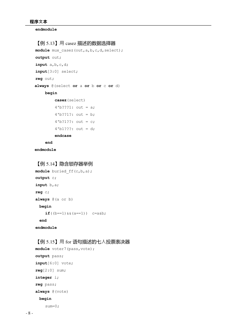
�
程序文本
endmodule
【例 5.13】用 casez 描述的数据选择器
module mux_casez(out,a,b,c,d,select);
output out;
input a,b,c,d;
input[3:0] select;
reg out;
always @(select or a or b or c or d)
begin
casez(select)
4'b???1: out = a;
4'b??1?: out = b;
4'b?1??: out = c;
4'b1???: out = d;
endcase
end
endmodule
【例 5.14】隐含锁存器举例
module buried_ff(c,b,a);
output c;
input b,a;
reg c;
always @(a or b)
begin
if((b==1)&&(a==1)) c=a&b;
end
endmodule
【例 5.15】用 for 语句描述的七人投票表决器
module voter7(pass,vote);
output pass;
input[6:0] vote;
reg[2:0] sum;
integer i;
reg pass;
always @(vote)
begin
sum=0;
- 8 -
�


 2023年江西萍乡中考道德与法治真题及答案.doc
 2012年重庆南川中考生物真题及答案.doc
 2013年江西师范大学地理学综合及文艺理论基础考研真题.doc
 2020年四川甘孜小升初语文真题及答案I卷.doc
 2020年注册岩土工程师专业基础考试真题及答案.doc
 2023-2024学年福建省厦门市九年级上学期数学月考试题及答案.doc
 2021-2022学年辽宁省沈阳市大东区九年级上学期语文期末试题及答案.doc
 2022-2023学年北京东城区初三第一学期物理期末试卷及答案.doc
 2018上半年江西教师资格初中地理学科知识与教学能力真题及答案.doc
 2012年河北国家公务员申论考试真题及答案-省级.doc
 2020-2021学年江苏省扬州市江都区邵樊片九年级上学期数学第一次质量检测试题及答案.doc
 2022下半年黑龙江教师资格证中学综合素质真题及答案.doc