logo资料库

MAN-G-DS301.pdf

第1页 / 共208页
第2页 / 共208页
第3页 / 共208页
第4页 / 共208页
第5页 / 共208页
第6页 / 共208页
第7页 / 共208页
第8页 / 共208页
资料共208页,剩余部分请下载后查看
Chapter 1: Introduction
1.1. Relevant Elmo Documentation
1.2. Terms and Abbreviations
1.3. Gold Line Communications
Chapter 2: CANopen Basics
2.1. Physical Layer
2.2. Standard vs. Extended Addressing
2.3. Client - Server Relations
2.4. RTR – Remote Transmission Request
2.5. Object Dictionary
2.6. Communication Objects
2.7. Object Dictionary - Data Types
2.7.1. PDO Communication Parameter - Object 0x20
2.7.2. PDO Mapping - Object 0x21
2.8. Servo Drive Device-Specific Data Types
2.8.1. PVT Data Parameters Object 0x40
2.8.2. PT Data Parameters - Object 0x41
2.8.3. Binary Interpreter Query - Object 0x42
2.8.4. Binary Interpreter Command - Object 0x43
2.8.5. DSP 402 PV Data - Object 0x44
2.8.6. Home On Block Limits - Object 0x45
2.8.7. DS402 Interpolated Time Period , Object 0x80
2.8.8. DSP 402 Interpolated Data Configuration - Object 0x81
2.8.9. DSP 402 Interpolated Data Record - Object 0x82
2.9. Representation of Numbers
Chapter 3: The Object Dictionary
Chapter 4: Service Data Objects (SDOs)
4.1. Initiate SDO Download Protocol
4.2. Download SDO Protocol
4.3. Initiate SDO Upload Protocol
4.4. Upload SDO Segment Protocol
4.5. Abort SDO Transfer Protocol
Example of SDO abort transfer
4.6. Uploading Data Using an SDO
Example of segmented SDO upload transfer
Example of an expedited upload SDO transfer
4.7. Downloading Data Using an SDO
Example of an expedited download SDO transfer
Chapter 5: Process Data Objects (PDOs)
5.1. PDO Mapping
5.1.1. Transmission Type
5.1.2. The Synchronous Trigger
5.1.3. The Asynchronous Trigger
5.1.4. Mapping Parameter Objects
5.1.5. Default Values
5.2. Receive PDOs
5.2.1. RPDO Error Handling
5.2.2. Mapping procedure
Example of RPDO mapping
5.3. Transmit PDOs
Example of TPDO mapping
Chapter 6: Emergency (EMCY)
6.1. Emergency Codes
6.2. ELMO Error Codes
Example of Emergency message
Chapter 7: Network Management (NMT)
7.1. NMT States
Examples of NMT message
Chapter 8: Boot-up Messages
8.1. Boot-up Event
Examples of boot-up message
Chapter 9: Heartbeat Messages
9.1. Producer message
Example of producer message
9.2. Consumer HB EMCY message
Example of HB EMCY message that was sent from ELMO drive
9.3. Support of two heartbeat producers
Example
Chapter 10: SYNC Messages
Chapter 11: Time Stamp
Chapter 12: Binary Interpreter Commands
12.1. Binary Interpreter Commands and Results
12.1.1. Set and Query Commands
12.1.1.1. RPDO2 Structure
Byte 3, bit 6
Example 1
Example 2
Example 3
Example 4
Example 5
Example 6
12.1.1.2. TPDO2 Structure
Byte 3, bit 6
Example 1
Example 2
12.1.2. Execute Command
Example
12.2. ASCII Interpreter Commands not Supported by Binary Interpreter
Chapter 13: The OS Interpreter
Example
Chapter 14: The EDS
Chapter 15: Communication Profile Objects
15.1. Object 0x1000: Device type
15.2. Object 0x1001: Error register
15.3. Object 0x1002: Manufacturer status register
15.4. Object 0x1003: Pre-defined error field
15.5. Object 0x1006: Communication Cycle Period
15.6. Object 0x1008: Manufacturer device name
15.7. Object 0x1009: Manufacturer hardware version
Example (in Hexadecimal)
15.8. Object 0x100A: Manufacturer software version
15.9. Object 0x100B: Node ID
15.10. Object 0x1010: Store parameters
Example of write SDO to object 0x1010 sub index 1
15.11. Object 0x1011: Restore parameters
Example of write SDO to object 0x1011 sub index 1
15.12. Object 0x1016: Consumer heartbeat time
15.13. Object 0x1017: Producer heartbeat time
15.14. Object 0x1018: Identity object
15.15. Object 0x1023: OS command and prompt
15.16. Object 0x1024: OS command mode
15.17. Object 0x1029: Error behavior
15.18. Objects 0x1400 - 0x1403: Receive PDO communication parameter
15.18.1. Description of RPDO transmission type, sub index 2
15.19. Objects 0x1600 - 0x1603: Receive PDO mapping
15.20. Objects 0x1800 - 0x1803: Transmit PDO communication parameter
15.20.1. Description of RPDO transmission type, sub index 2
15.20.1.1. Inhibit Time
15.20.1.2. Event Timer
15.21. Objects 0x1A00 - 0x1A03: Transmit PDO mapping parameter
Chapter 16: Manufacturer-specific Objects
16.1. Object 0x2005: Fast Reference
16.2. Object 0x2012: Binary interpreter input
16.3. Object 0x2013: Binary interpreter output
16.4. Object 0x2020: Home on block limit parameters
16.5. Object 0x2030: Recorder data
Example of uploading recorded data
16.6. Object 0x2035: Upload Data Parameters
16.7. Object 0x2036: Upload Data
16.8. Object 0x2041: Timestamp (free running timer)
16.9. Object 0x2045
16.10. Object 0x2051: Download Data
16.11. Object 0x2060: Drive Parameters Checksum
16.12. Object 0x207B: Additional Position Range Limit
Example (all messages in hexadecimal)
16.13. Object 0x2081: Extended Error Code
16.14. Object 0x2082: CAN controller status
16.15. Object 0x2085: Extra status register
16.16. Object 0x2086 STO status register
16.17. Object 0x2087: PAL Version
16.18. Object 0x2090: Firmware download
16.19. Object 0x20A0: Auxiliary position actual value
16.20. Object 0x20B0: Socket Additional Function
16.21. Object 0x20FC: Absolute Sensor Functions
16.22. Object 0x20FD: Digital Inputs
Example
16.23. Object 0x2201: Digital input low byte
16.24. Object 0x2202: Extended input
16.25. Object 0x2203: Application Object
16.26. Object 0x2205: Analog Input Object
Example:
16.27. Object 0x2206: 5V DC supply
16.28. Object 0x22A0: Digital Outputs
16.29. Object 0x22A1: Extended Outputs
16.30. Object 0x22A2: Drive Temperature in ˚C
16.31. Object 0x22A3: Temperature Array
16.32. Object 0x2E06: Torque Window
16.33. Object 0x2E07: Torque Window Time
16.34. Object 0x2E10: Home Position on Touch Probe Capture
16.35. Object 0x2E15: Gantry YAW offset
16.36. Object 0x2F00: User Integer
16.37. Object 0x2F01: User Float Array
16.38. Object 0x2F05: Get drive control board type
16.39. Object 0x2F20: TPDO asynchronous events
16.40. Object 0x2F21: Emergency events
16.41. Object 0x2F41: DS402 Configuration object
16.42. Object 0x2F45: Threshold parameter
16.43. Object 0x2F70 – CAN Encoder Range
16.44. Object 0x2F75 – Extrapolation Cycles Timeout
Chapter 17: ECAT only Objects
17.1. Object 0x10E0: Device ID reload
17.2. Object 0x1C12: SM2 (Outputs) PDO assignments
17.3. Object 0x1C13: SM3 (Inputs) PDO assignments
17.4. Object 0x10F1: Sync Error Setting
17.5. Object 0x2046: DC Clock inhibit time
17.6. Object 0x2061: FoE Download Parameters Error
17.7. Object 0x2062: FoE Parameters Last Processed Command
17.8. Object 0x20E0: ECAT alias ID object
Chapter 18: Little and Big Endians
Gold DS-301 Implementation Guide April 2014 (Ver. 1.006) www.elmomc.com Table of Contents |Relevant Elmo Documentation|www.elmomc.com
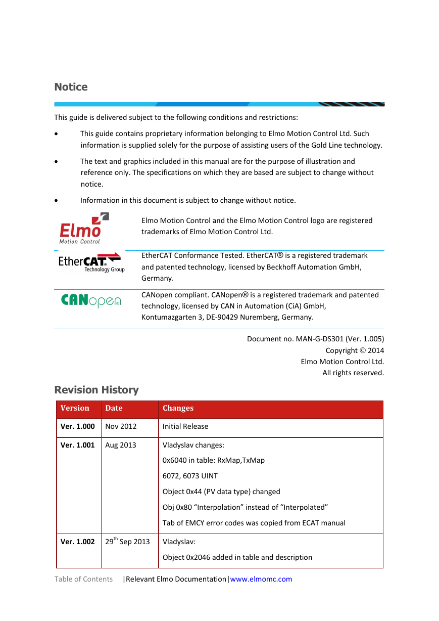
Notice This guide is delivered subject to the following conditions and restrictions: • This guide contains proprietary information belonging to Elmo Motion Control Ltd. Such information is supplied solely for the purpose of assisting users of the Gold Line technology. • • The text and graphics included in this manual are for the purpose of illustration and reference only. The specifications on which they are based are subject to change without notice. Information in this document is subject to change without notice. Elmo Motion Control and the Elmo Motion Control logo are registered trademarks of Elmo Motion Control Ltd. EtherCAT Conformance Tested. EtherCAT® is a registered trademark and patented technology, licensed by Beckhoff Automation GmbH, Germany. CANopen compliant. CANopen® is a registered trademark and patented technology, licensed by CAN in Automation (CiA) GmbH, Kontumazgarten 3, DE-90429 Nuremberg, Germany. Document no. MAN-G-DS301 (Ver. 1.005) Copyright  2014 Elmo Motion Control Ltd. All rights reserved. Revision History Version Date Changes Ver. 1.000 Nov 2012 Initial Release Ver. 1.001 Aug 2013 Vladyslav changes: 0x6040 in table: RxMap,TxMap 6072, 6073 UINT Object 0x44 (PV data type) changed Obj 0x80 “Interpolation” instead of “Interpolated” Tab of EMCY error codes was copied from ECAT manual Ver. 1.002 29th Sep 2013 Vladyslav: Object 0x2046 added in table and description Table of Contents |Relevant Elmo Documentation|www.elmomc.com
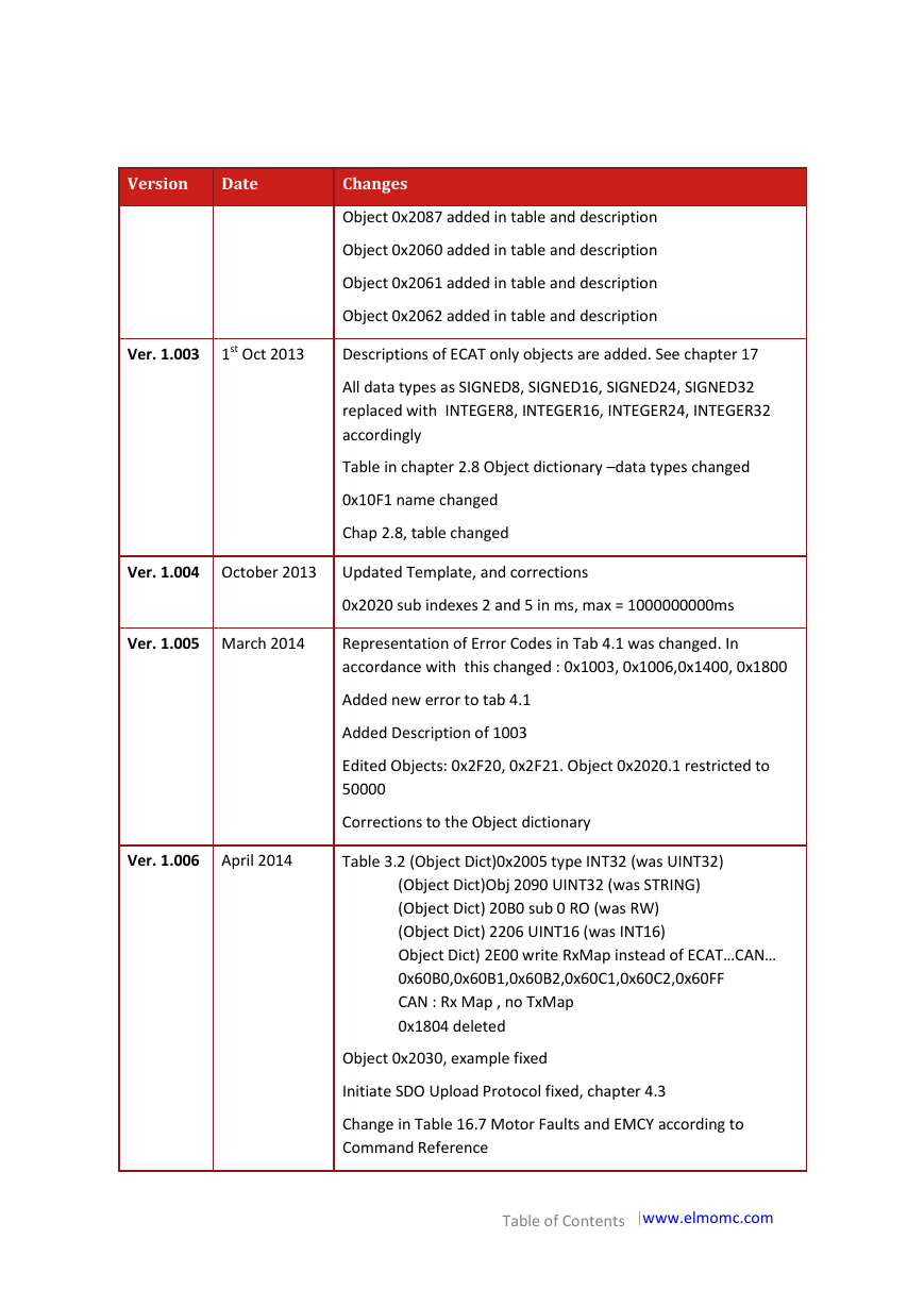
Version Date Changes Object 0x2087 added in table and description Object 0x2060 added in table and description Object 0x2061 added in table and description Object 0x2062 added in table and description Ver. 1.003 1st Oct 2013 Descriptions of ECAT only objects are added. See chapter 17 All data types as SIGNED8, SIGNED16, SIGNED24, SIGNED32 replaced with INTEGER8, INTEGER16, INTEGER24, INTEGER32 accordingly Table in chapter 2.8 Object dictionary –data types changed 0x10F1 name changed Chap 2.8, table changed Ver. 1.004 October 2013 Updated Template, and corrections 0x2020 sub indexes 2 and 5 in ms, max = 1000000000ms Ver. 1.005 March 2014 Representation of Error Codes in Tab 4.1 was changed. In accordance with this changed : 0x1003, 0x1006,0x1400, 0x1800 Ver. 1.006 April 2014 Added new error to tab 4.1 Added Description of 1003 Edited Objects: 0x2F20, 0x2F21. Object 0x2020.1 restricted to 50000 Corrections to the Object dictionary Table 3.2 (Object Dict)0x2005 type INT32 (was UINT32) (Object Dict)Obj 2090 UINT32 (was STRING) (Object Dict) 20B0 sub 0 RO (was RW) (Object Dict) 2206 UINT16 (was INT16) Object Dict) 2E00 write RxMap instead of ECAT…CAN… 0x60B0,0x60B1,0x60B2,0x60C1,0x60C2,0x60FF CAN : Rx Map , no TxMap 0x1804 deleted Object 0x2030, example fixed Initiate SDO Upload Protocol fixed, chapter 4.3 Change in Table 16.7 Motor Faults and EMCY according to Command Reference Table of Contents |www.elmomc.com
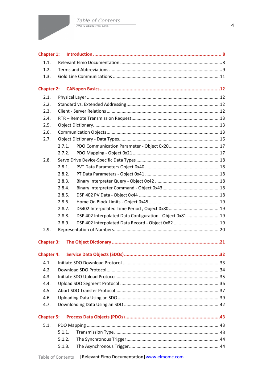
Table of Contents MAN-G-DS301 (Ver. 1.006) 4 Chapter 1: Introduction ............................................................................................... 8 Relevant Elmo Documentation .................................................................................. 8 1.1. 1.2. Terms and Abbreviations ........................................................................................... 9 1.3. Gold Line Communications ...................................................................................... 11 Chapter 2: CANopen Basics ......................................................................................... 12 Physical Layer ........................................................................................................... 12 2.1. Standard vs. Extended Addressing ........................................................................... 12 2.2. Client - Server Relations ........................................................................................... 12 2.3. 2.4. RTR – Remote Transmission Request ....................................................................... 13 2.5. Object Dictionary ...................................................................................................... 13 2.6. Communication Objects ........................................................................................... 13 2.7. Object Dictionary - Data Types ................................................................................. 16 PDO Communication Parameter - Object 0x20 ......................................... 17 2.7.1. 2.7.2. PDO Mapping - Object 0x21 ...................................................................... 17 Servo Drive Device-Specific Data Types ................................................................... 18 2.8.1. PVT Data Parameters Object 0x40 ............................................................ 18 PT Data Parameters - Object 0x41 ............................................................ 18 2.8.2. Binary Interpreter Query - Object 0x42 .................................................... 18 2.8.3. 2.8.4. Binary Interpreter Command - Object 0x43 .............................................. 18 2.8.5. DSP 402 PV Data - Object 0x44 ................................................................. 18 2.8.6. Home On Block Limits - Object 0x45 ......................................................... 19 DS402 Interpolated Time Period , Object 0x80 ......................................... 19 2.8.7. 2.8.8. DSP 402 Interpolated Data Configuration - Object 0x81 .......................... 19 2.8.9. DSP 402 Interpolated Data Record - Object 0x82 ..................................... 19 Representation of Numbers ..................................................................................... 20 2.9. 2.8. Chapter 3: The Object Dictionary ................................................................................ 21 Chapter 4: Service Data Objects (SDOs) ....................................................................... 32 Initiate SDO Download Protocol .............................................................................. 33 4.1. Download SDO Protocol ........................................................................................... 34 4.2. 4.3. Initiate SDO Upload Protocol ................................................................................... 35 4.4. Upload SDO Segment Protocol ................................................................................ 36 4.5. Abort SDO Transfer Protocol .................................................................................... 37 4.6. Uploading Data Using an SDO .................................................................................. 39 4.7. Downloading Data Using an SDO ............................................................................. 42 Chapter 5: 5.1. Process Data Objects (PDOs) ...................................................................... 43 PDO Mapping ........................................................................................................... 43 Transmission Type ..................................................................................... 43 5.1.1. The Synchronous Trigger ........................................................................... 44 5.1.2. 5.1.3. The Asynchronous Trigger ......................................................................... 44 Table of Contents |Relevant Elmo Documentation|www.elmomc.com
Table of Contents MAN-G-DS301 (Ver. 1.006) 5 5.1.4. Mapping Parameter Objects ..................................................................... 44 5.1.5. Default Values ........................................................................................... 44 Receive PDOs ............................................................................................................ 45 5.2.1. RPDO Error Handling ................................................................................. 45 5.2.2. Mapping procedure ................................................................................... 46 Transmit PDOs .......................................................................................................... 49 5.2. 5.3. Chapter 6: Emergency (EMCY) .................................................................................... 51 Emergency Codes ..................................................................................................... 51 ELMO Error Codes .................................................................................................... 57 6.1. 6.2. Chapter 7: Network Management (NMT) .................................................................... 66 7.1. NMT States ............................................................................................................... 67 Chapter 8: 8.1. Boot-up Messages ..................................................................................... 68 Boot-up Event ........................................................................................................... 68 Chapter 9: Heartbeat Messages .................................................................................. 69 Producer message .................................................................................................... 70 Consumer HB EMCY message .................................................................................. 70 Support of two heartbeat producers ....................................................................... 71 9.1. 9.2. 9.3. Chapter 10: SYNC Messages.......................................................................................... 72 Chapter 11: Time Stamp ............................................................................................... 72 Chapter 12: Binary Interpreter Commands .................................................................... 73 12.1. Binary Interpreter Commands and Results .............................................................. 75 12.1.1. Set and Query Commands ......................................................................... 75 12.1.1.1. RPDO2 Structure....................................................................... 75 12.1.1.2. TPDO2 Structure ....................................................................... 77 12.1.2. Execute Command..................................................................................... 78 12.2. ASCII Interpreter Commands not Supported by Binary Interpreter ........................ 79 Chapter 13: The OS Interpreter ..................................................................................... 80 Chapter 14: The EDS ..................................................................................................... 82 Chapter 15: Communication Profile Objects .................................................................. 83 15.1. Object 0x1000: Device type ..................................................................................... 83 15.2. Object 0x1001: Error register ................................................................................... 84 15.3. Object 0x1002: Manufacturer status register .......................................................... 85 15.4. Object 0x1003: Pre-defined error field .................................................................... 86 15.5. Object 0x1006: Communication Cycle Period .......................................................... 88 Table of Contents |www.elmomc.com
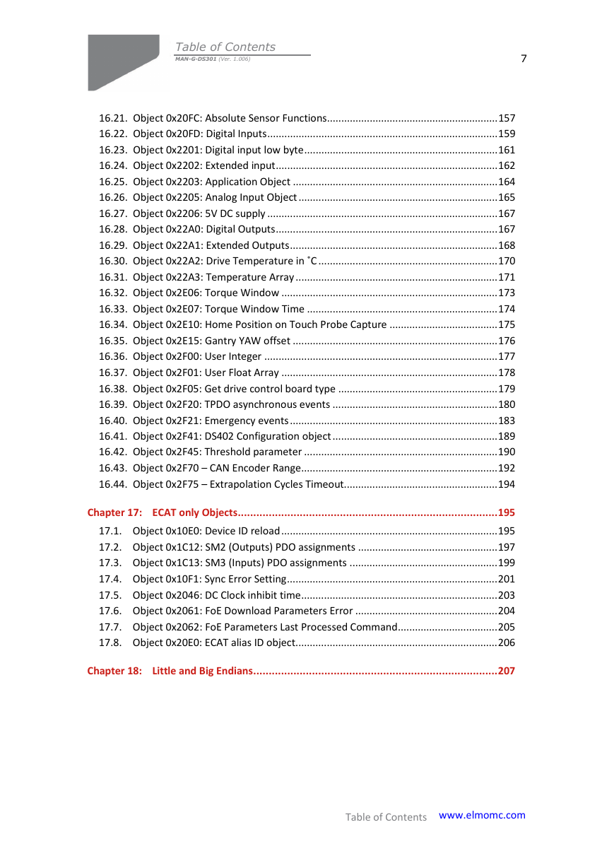
Table of Contents MAN-G-DS301 (Ver. 1.006) 6 15.6. Object 0x1008: Manufacturer device name ............................................................ 89 15.7. Object 0x1009: Manufacturer hardware version ..................................................... 90 15.8. Object 0x100A: Manufacturer software version ...................................................... 92 15.9. Object 0x100B: Node ID ........................................................................................... 93 15.10. Object 0x1010: Store parameters ............................................................................ 94 15.11. Object 0x1011: Restore parameters ........................................................................ 96 15.12. Object 0x1016: Consumer heartbeat time ............................................................... 98 15.13. Object 0x1017: Producer heartbeat time .............................................................. 100 15.14. Object 0x1018: Identity object ............................................................................... 101 15.15. Object 0x1023: OS command and prompt ............................................................. 103 15.16. Object 0x1024: OS command mode ...................................................................... 105 15.17. Object 0x1029: Error behavior ............................................................................... 106 15.18. Objects 0x1400 - 0x1403: Receive PDO communication parameter .................... 107 15.18.1. Description of RPDO transmission type, sub index 2 .............................. 110 15.19. Objects 0x1600 - 0x1603: Receive PDO mapping .................................................. 111 15.20. Objects 0x1800 - 0x1803: Transmit PDO communication parameter .................. 115 15.20.1. Description of RPDO transmission type, sub index 2 .............................. 119 15.20.1.1. Inhibit Time............................................................................. 119 15.20.1.2. Event Timer ............................................................................ 119 15.21. Objects 0x1A00 - 0x1A03: Transmit PDO mapping parameter .............................. 120 Chapter 16: Manufacturer-specific Objects ................................................................. 123 16.1. Object 0x2005: Fast Reference .............................................................................. 123 16.2. Object 0x2012: Binary interpreter input ................................................................ 124 16.3. Object 0x2013: Binary interpreter output ............................................................. 124 16.4. Object 0x2020: Home on block limit parameters .................................................. 125 Home On Block Limits, Object 0x45 ....................................................................... 125 16.5. Object 0x2030: Recorder data ............................................................................... 127 16.6. Object 0x2035: Upload Data Parameters ............................................................... 135 16.7. Object 0x2036: Upload Data .................................................................................. 135 16.8. Object 0x2041: Timestamp (free running timer) ................................................... 136 16.9. Object 0x2045 ........................................................................................................ 137 16.10. Object 0x2051: Download Data ............................................................................. 137 16.11. Object 0x2060: Drive Parameters Checksum ......................................................... 138 16.12. Object 0x207B: Additional Position Range Limit .................................................... 139 16.13. Object 0x2081: Extended Error Code ..................................................................... 143 16.14. Object 0x2082: CAN controller status .................................................................... 145 16.15. Object 0x2085: Extra status register ...................................................................... 148 16.16. Object 0x2086 STO status register ......................................................................... 150 16.17. Object 0x2087: PAL Version ................................................................................... 152 16.18. Object 0x2090: Firmware download ...................................................................... 153 16.19. Object 0x20A0: Auxiliary position actual value ...................................................... 153 16.20. Object 0x20B0: Socket Additional Function ........................................................... 154 Table of Contents |www.elmomc.com
Table of Contents MAN-G-DS301 (Ver. 1.006) 7 16.21. Object 0x20FC: Absolute Sensor Functions ............................................................ 157 16.22. Object 0x20FD: Digital Inputs ................................................................................. 159 16.23. Object 0x2201: Digital input low byte .................................................................... 161 16.24. Object 0x2202: Extended input .............................................................................. 162 16.25. Object 0x2203: Application Object ........................................................................ 164 16.26. Object 0x2205: Analog Input Object ...................................................................... 165 16.27. Object 0x2206: 5V DC supply ................................................................................. 167 16.28. Object 0x22A0: Digital Outputs .............................................................................. 167 16.29. Object 0x22A1: Extended Outputs ......................................................................... 168 16.30. Object 0x22A2: Drive Temperature in ˚C ............................................................... 170 16.31. Object 0x22A3: Temperature Array ....................................................................... 171 16.32. Object 0x2E06: Torque Window ............................................................................ 173 16.33. Object 0x2E07: Torque Window Time ................................................................... 174 16.34. Object 0x2E10: Home Position on Touch Probe Capture ...................................... 175 16.35. Object 0x2E15: Gantry YAW offset ........................................................................ 176 16.36. Object 0x2F00: User Integer .................................................................................. 177 16.37. Object 0x2F01: User Float Array ............................................................................ 178 16.38. Object 0x2F05: Get drive control board type ........................................................ 179 16.39. Object 0x2F20: TPDO asynchronous events .......................................................... 180 16.40. Object 0x2F21: Emergency events ......................................................................... 183 16.41. Object 0x2F41: DS402 Configuration object .......................................................... 189 16.42. Object 0x2F45: Threshold parameter .................................................................... 190 16.43. Object 0x2F70 – CAN Encoder Range ..................................................................... 192 16.44. Object 0x2F75 – Extrapolation Cycles Timeout...................................................... 194 Chapter 17: ECAT only Objects .................................................................................... 195 17.1. Object 0x10E0: Device ID reload ............................................................................ 195 17.2. Object 0x1C12: SM2 (Outputs) PDO assignments ................................................. 197 17.3. Object 0x1C13: SM3 (Inputs) PDO assignments .................................................... 199 17.4. Object 0x10F1: Sync Error Setting .......................................................................... 201 17.5. Object 0x2046: DC Clock inhibit time ..................................................................... 203 17.6. Object 0x2061: FoE Download Parameters Error .................................................. 204 17.7. Object 0x2062: FoE Parameters Last Processed Command ................................... 205 17.8. Object 0x20E0: ECAT alias ID object ....................................................................... 206 Chapter 18: Little and Big Endians ............................................................................... 207 Table of Contents |www.elmomc.com
Gold DS-301 Implementation Guide MAN-G-DS301 (Ver. 1.006) 8 Chapter 1: Introduction This manual explains how to implement EtherCAT and CANopen DS-301 communication with Elmo’s Gold DSP-based digital servo drives. It provides a description of the Gold drives and the means of implementing communication based on the EtherCAT and CiA CANopen protocols. Most of the Gold functionality is standard, according to CiA documents DS-301, version 4.01, DSP 402 (proprietary) and the CiA OS interpreter. In this document, emphasis is placed on manufacturer-specific behaviors, although it also repeats certain CiA standard material, to enhance understanding and to complete certain descriptions. The manual contains data which is relevant to the operation of the Elmo drive. 1.1. Relevant Elmo Documentation This manual is part of the Elmo Gold documentation set, which also includes: • Gold Installation Guides, which provide full instructions for installing the Gold digital servo drives. • • • The EAS User Manual, which includes explanations of all the software tools that are a part of Elmo’s Application Software environment. The Gold Command Reference Manual, which describes, in detail, each software command used to manipulate the motion controller. This is the main source of detailed explanations of all Gold commands mentioned in this manual. The Gold Language & User Program Manual, which describes the comprehensive software used with Gold digital servo drives Table of Contents |Relevant Elmo Documentation|www.elmomc.com
分享到:
收藏