DIN SPEC 70121
Dezember 2014
D
ICS 43.120; 29.160.40
Ersatz für
DIN SPEC 70121:2012-08
Elektromobilität –
Digitale Kommunikation zwischen einer Gleichstrom-Ladestation und
einem Elektrofahrzeug zur Regelung der Gleichstromladung im
Verbund-Ladesystem; Text in Englisch
Electromobility –
Digital communication between a d.c. EV charging station and an electric vehicle for
control of d.c. charging in the Combined Charging System; Text in English
Électromobilité –
Communication digitale entre la borne de recharge à courant continu et la véhicule
éléctrique pour régler la charge à courant continu dans le système de charge
combiné (CCS); Texte en anglais
Zur Erstellung einer DIN SPEC können verschiedene Verfahrensweisen herangezogen werden:
Das vorliegende Dokument wurde nach den Verfahrensregeln einer Vornorm erstellt.
Gesamtumfang 212 Seiten
DIN-Normenausschuss Automobiltechnik (NAAutomobil)
©
DIN Deutsches Institut für Normung e. V. · Jede Art der Vervielfältigung, auch auszugsweise,
nur mit Genehmigung des DIN Deutsches Institut für Normung e. V., Berlin, gestattet.
Alleinverkauf der Spezifikationen durch Beuth Verlag GmbH, 10772 Berlin
Preisgruppe 38
www.din.de
www.beuth.de
!%=b/"
2266312
Deutsches Institut f¨¹r Normung e. V.Provided by IHS under license with DINLicensee=Shanghai Institute of Standardization269 5908977Not for Resale, 2016-1-29 01:21:27 No reproduction or networking permitted without license from IHS--`,``,`,,,`,`,,`````,,,`-`-``,```,,,`---�
DIN SPEC 70121:2014-12
Table of Content
Seite
Foreword ......................................................................................................................................................... 3
1
Scope ................................................................................................................................................. 5
Normative references ....................................................................................................................... 5
2
Terms and definitions ...................................................................................................................... 7
3
4
Symbols and abbreviated terms ................................................................................................... 13
Relation to other standards ........................................................................................................... 15
5
Conventions .................................................................................................................................... 15
6
6.1
Definition of OSI based services ................................................................................................... 15
6.2
Requirement structure ................................................................................................................... 15
Notation used for XML schema diagrams .................................................................................... 16
6.3
DC Charging System Architecture ................................................................................................ 17
7
7.1
System schematics of DC charging system ................................................................................ 17
7.2
Pilot function ................................................................................................................................... 17
Communication Stack .................................................................................................................... 17
7.3
EV-EVSE Communication .............................................................................................................. 18
8
8.1
Basic requirements for V2G Communication .............................................................................. 18
Service primitive concept of OSI layered architecture ............................................................... 18
8.2
Physical and Data Link Layer ........................................................................................................ 19
8.3
8.4
V2G communication states ............................................................................................................ 69
8.5
Network Layer ................................................................................................................................. 73
8.6
Transport Layer ............................................................................................................................... 75
V2G Transfer Protocol .................................................................................................................... 76
8.7
8.8
Presentation Layer.......................................................................................................................... 81
Application Layer ............................................................................................................................ 84
8.9
9
Application Layer messages ......................................................................................................... 92
General information and definitions ............................................................................................. 92
9.1
Protocol handshake ....................................................................................................................... 92
9.2
9.3
Message structure .......................................................................................................................... 96
9.4
BodyElement Definitions ............................................................................................................... 99
Complex data types ...................................................................................................................... 123
9.5
9.6
Session timing and error handling ............................................................................................. 150
9.7
Message sequences ..................................................................................................................... 161
Annex A (normative) XML Schema application layer messages ......................................................... 180
Annex B (informative) Difference between Multi-Network Broadcast, Broadcast, and Unicast ...... 211
Bibliography ............................................................................................................................................... 212
2Deutsches Institut f¨¹r Normung e. V.Provided by IHS under license with DINLicensee=Shanghai Institute of Standardization269 5908977Not for Resale, 2016-1-29 01:21:27 No reproduction or networking permitted without license from IHS--`,``,`,,,`,`,,`````,,,`-`-``,```,,,`---�
DIN SPEC 70121:2014-12
Foreword
This document has been prepared by Working Group NA 052-01-03-17 AK “Vehicle to grid communication
interface (V2G-CI)” of the DIN Standards Committe Road Vehicle Engineering (NAAutomobil).
A DIN SPEC adopted as a Pre-standard is the result of standardization that is not published by DIN as a
Standard owing to certain reservations as to its content or owing to the process of its development deviating
from that of a standard.
A draft for this DIN SPEC has not been published.
Experiences made with this DIN SPEC are welcome
preferably as a file in tabular form submitted via e-Mail an NAAutomobil@vda.de. The template of
this table can be retrieved from the internet under http://www.din.de/stellungnahme;
or in paper form forwarded to Normenausschuss Automobiltechnik, Behrenstr. 35, 10117 Berlin,
Germany.
Attention is drawn to the possibility that some of the elements of this document may be the subject of patent
rights. DIN [and/or] DKE shall not be held responsible for identifying any or all such patents rights.
Amendments
With regard to DIN SPEC 70121:2012-08, the following amendments have been made:
a) clause 2: Several normative references have been added;
b) clause 3: List of terms and definitions has been revised;
c) previous sub-clause 7.1 (list of use cases) has been deleted;
d) clause 8: Various subclauses have been revised:
1) subclause 8.3: “HomePlug Green PHY“ were added (e.g. „NUM_SOUNDS“
„CM_SLAC_PARM.CNF“ has been changed into 0xA, etc.);
in message
2) subclauses 8.3.3 und 8.3.5 have been revised;
3) subclause 8.9: Several use case services have been added.
e) clause 9: Serveral requirements have been added with the complete section;
f)
cubclause 9.5.2.5. has been added;
g) annex B has been added.
Previous editions
DIN SPEC 70121: 2012-08
3Deutsches Institut f¨¹r Normung e. V.Provided by IHS under license with DINLicensee=Shanghai Institute of Standardization269 5908977Not for Resale, 2016-1-29 01:21:27 No reproduction or networking permitted without license from IHS--`,``,`,,,`,`,,`````,,,`-`-``,```,,,`---�
DIN SPEC 70121:2014-12
Introduction
The time consumption for electrical vehicles (EVs) charging process is determined by the maximum power,
which can be transferred to the EV. The alternating current (AC) charging has a fixed limited voltage (e.g.
400 V in Europe) and therefore an increasing of power supply can only be achieved by higher currents. This
approach is limited by the cable weight, because a higher current requires a greater cross section of the
copper cable. As the user must be able to connect the EV with the EVSE the charging cable should not be
heavier than a typical fuel tube of a filling Station today. A further disadvantage of the AC charging approach
is that the rectifier must be placed in the EV. This results in an increase of the overall EV weight and
complexity of it as depending on a size of the rectifier, a special liquid cooling system may be required for it.
The weight of a rectifier however increases with the power it can handle. These disadvantages can be
prevented by using a DC charging approach. In this case the rectifier is placed in the EVSE and the used
voltage is limited by the maximum battery voltage (typically 400-800 volt), which is normally higher than the
AC voltage.
The drawback of the DC charging solution is that the communication real time requirements on the EV-EVSE
interface increases as the rectifier and the battery management system must be able to communicate via this
interface. The prevention of an incorrect charging state requires a real time communication, which is tailored
to the charging process. The real time requirements depend on the battery system and are subjects of further
investigations.
The main aspects of this specification are
Support of the Combined Charging System based on IEC 61851-23;
Aligned charging process with SAE J2847/2;
Ease of integration of SEP2.0 or similar XML based approach for V2G Communications.
4Deutsches Institut f¨¹r Normung e. V.Provided by IHS under license with DINLicensee=Shanghai Institute of Standardization269 5908977Not for Resale, 2016-1-29 01:21:27 No reproduction or networking permitted without license from IHS--`,``,`,,,`,`,,`````,,,`-`-``,```,,,`---�
DIN SPEC 70121:2014-12
1 Scope
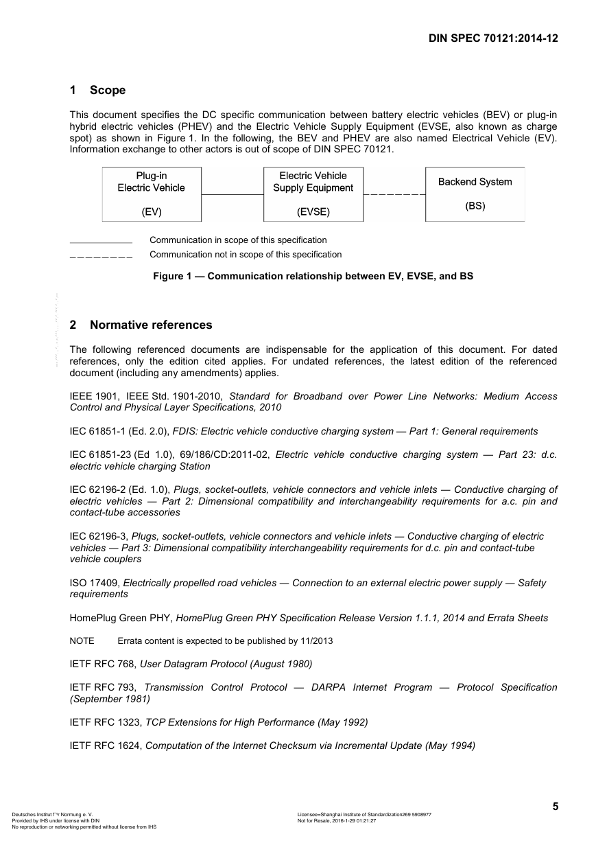
This document specifies the DC specific communication between battery electric vehicles (BEV) or plug-in
hybrid electric vehicles (PHEV) and the Electric Vehicle Supply Equipment (EVSE, also known as charge
spot) as shown in Figure 1. In the following, the BEV and PHEV are also named Electrical Vehicle (EV).
Information exchange to other actors is out of scope of DIN SPEC 70121.
Communication in scope of this specification
Communication not in scope of this specification
Figure 1 — Communication relationship between EV, EVSE, and BS
2 Normative references
The following referenced documents are indispensable for the application of this document. For dated
references, only the edition cited applies. For undated references, the latest edition of the referenced
document (including any amendments) applies.
IEEE 1901, IEEE Std. 1901-2010, Standard for Broadband over Power Line Networks: Medium Access
Control and Physical Layer Specifications, 2010
IEC 61851-1 (Ed. 2.0), FDIS: Electric vehicle conductive charging system — Part 1: General requirements
IEC 61851-23 (Ed 1.0), 69/186/CD:2011-02, Electric vehicle conductive charging system — Part 23: d.c.
electric vehicle charging Station
IEC 62196-2 (Ed. 1.0), Plugs, socket-outlets, vehicle connectors and vehicle inlets ― Conductive charging of
electric vehicles ― Part 2: Dimensional compatibility and interchangeability requirements for a.c. pin and
contact-tube accessories
IEC 62196-3, Plugs, socket-outlets, vehicle connectors and vehicle inlets ― Conductive charging of electric
vehicles ― Part 3: Dimensional compatibility interchangeability requirements for d.c. pin and contact-tube
vehicle couplers
ISO 17409, Electrically propelled road vehicles ― Connection to an external electric power supply ― Safety
requirements
HomePlug Green PHY, HomePlug Green PHY Specification Release Version 1.1.1, 2014 and Errata Sheets
NOTE
Errata content is expected to be published by 11/2013
IETF RFC 768, User Datagram Protocol (August 1980)
IETF RFC 793, Transmission Control Protocol — DARPA Internet Program — Protocol Specification
(September 1981)
IETF RFC 1323, TCP Extensions for High Performance (May 1992)
IETF RFC 1624, Computation of the Internet Checksum via Incremental Update (May 1994)
5Deutsches Institut f¨¹r Normung e. V.Provided by IHS under license with DINLicensee=Shanghai Institute of Standardization269 5908977Not for Resale, 2016-1-29 01:21:27 No reproduction or networking permitted without license from IHS--`,``,`,,,`,`,,`````,,,`-`-``,```,,,`---�
DIN SPEC 70121:2014-12
IETF RFC 1981, Path MTU Discovery for IP version 6 (August 1996)
IETF RFC 2018, TCP Selective Acknowledgment Options (October 1996)
IETF RFC 2460, Internet Protocol, Version 6 (IPv6) Specification (December 1998)
IETF RFC 2988, Computing TCP's Retransmission Timer (November 2000)
IETF RFC 3122, Extensions to IPv6 Neighbor Discovery for Inverse Discovery Specification (June 2001)
IETF RFC 3484, Default Address Selection for Internet Protocol version 6 (IPv6) (February 2003)
IETF RFC 6582, The NewReno Modification to TCP's Fast Recovery Algorithm (April 2012)
4286, Multicast Router Discovery (December 2005)
IETF RFC 4291, IP Version 6 Addressing Architecture (February 2006)
IETF RFC 4294, IPv6 Node Requirements (April 2006)
IETF RFC 4429, Optimistic Duplicate Address Detection (DAD) for IPv6
IETF RFC 4443, Internet Control Message Protocol (ICMP v6) for the Internet Protocol version 6 (IPv6)
specification (March 2006)
IETF RFC 4861, Neighbour Discovery for IP version 6 (IPv6)
IETF RFC 4862, IPv6 Stateless Address Autoconfiguration (September 2007)
IETF RFC 4884, Extended ICMP to Support Multi-Part Messages (April 2007)
IETF RFC 5095, Deprecation of Type 0 Routing Headers in IPv6 (December 2007)
IETF RFC 5220, Problem Statement for Default Address Selection in Multi-Prefix Environments: Operational
Issues of RFC 3484 Default Rules (July 2008)
IETF RFC 5482, TCP User Timeout Option (March 2009)
IETF RFC 5681, TCP Congestion Control (September 2009)
IETF RFC 5722, Handling of Overlapping IPv6 Fragments (December 2009)
IETF RFC 5871, IANA Allocation Guidelines for the IPv6 Routing Header (May 2010)
IETF RFC 6298, Computing TCP's Retransmission Timer (June 2011)
IETF RFC 6335, Internet Assigned Numbers Authority (IANA) Procedures for the Management of the Service
Name and Transfer Protocol Port Number Registry (August 2011)
DIN SPEC 91286:2011-11, Electric mobility — Schemes of identifiers for E-Roaming — Contract ID and
Electric Vehicle Supply Equipment ID
SAE J1772, SAE Electric Vehicle and Plug in Hybrid Electric Vehicle Conductive Charge Coupler
SAE J2847/2 Communication between Plug-in Vehicles and Off-Board DC Chargers
W3C EXI 1.0, Efficient XML Interchange (EXI) Format 1.0, W3C Recommendation (March 2011)
6Deutsches Institut f¨¹r Normung e. V.Provided by IHS under license with DINLicensee=Shanghai Institute of Standardization269 5908977Not for Resale, 2016-1-29 01:21:27 No reproduction or networking permitted without license from IHS--`,``,`,,,`,`,,`````,,,`-`-``,```,,,`---�
DIN SPEC 70121:2014-12
3 Terms and definitions
For the purposes of this document, the following terms and definitions apply.
NOTE
In the context of this document, the term EVSE refers to the charging equipment, external to the EV.
3.1
Amplitude map
specifies a transmit power-reduction factor for each subcarrier related to the Tone Map
3.2
Central Coordinator (CCo)
the manager of a HomePlug Green PHY network
3.3
Channel Access Priority (CAP)
a method to prioritize the channel access (see HomePlug Green PHY specification)
3.4
Charging session
time between the beginning (connection of the cable) and the end (disconnection of the cable) of a charging
process
3.5
Coexistence
ability of different Green PHY systems to share the same physical media and to function simultaneously
3.6
Communication Media
the physical media carrying the Green PHY signal is given by the cable assembly, which connects the
charging infrastructure and the EV
3.7
Communication Setup Timer
timer that monitors the time from plug-in until reception of the SessionSetupRes message by the EV
3.8
Connection coordination
the entity which provides the whole functionality for EV to EVSE Matching and initialization, via the Data Link
Control SAP. This entity also controls the relationships between the basic signaling and the upper layers
The entity indicates link status and error information to higher layers. The control of the low-layer
communication Network Management parameters is handled over the Data Link Control SAP
3.9
Control Service Access Point (SAP)
Port or logical connection point to a network layer protocol
3.10
CP_EVSE_Function
summary of functionalities according to IEC 61851-1 within the EVSE, e.g. generation Control Pilot duty cycle;
control interface; to turn on/off charging power; safety control functions
3.11
CPLT
Control Pilot Line Transmission according to IEC 61851-1 and SAE J1772
7Deutsches Institut f¨¹r Normung e. V.Provided by IHS under license with DINLicensee=Shanghai Institute of Standardization269 5908977Not for Resale, 2016-1-29 01:21:27 No reproduction or networking permitted without license from IHS--`,``,`,,,`,`,,`````,,,`-`-``,```,,,`---�
DIN SPEC 70121:2014-12
3.12
Crosstalk
Capacitive or inductive coupling between two individual electric circuits, each providing a media for a Green
PHY network, in a way that the two networks are influenced by each other
3.13
Data Link Control Service Access Point (SAP)
Port or logical connection point between data link and network layer
3.14
DATA SAP
a Service Access Point that defines the interface between Layer 2 and Layer 3 for exchange of V2G related
payload
3.15
Electric Vehicle Communication Controller (EVCC)
entity which implements the communication to one or multiple SECCs
3.16
ETH SAP
the Ethernet II-class SAP supports applications using Ethernet II Class packets, including IEEE 802.3 with or
without IEEE 802.2 (LLC), IEEE 802.1H (SNAP) extensions, and/or VLAN tagging
3.17
Frame
Message on data link layer level
NOTE
information required on data link layer as e.g. synchronization information)
A Frame can include a IP-packet in its payload (framing the higher level packet and adding additional
3.18
Global address
IP address with unlimited scope
3.19
Green PHY Bridge
System that allows an EVSE’s Green PHY node to communicate on an external network of the EVSE, by
converting Green PHY to any other PHY. This bridge acts on OSI-layer 2
3.20
Green PHY module
functional assembly behind each socket outlet (IEC61851-1 case B) or each connector (IEC61851-1 case C)
which includes the Green PHY node, and the Connection Coordination functionality
3.21
Green PHY node
device equipped with a HomePlug Green PHY compatible modem chip. It characterises one logical and
physical communication device that is attached to a physical media, and is capable of sending, receiving, or
forwarding information over a HomePlug Green PHY communication channel
3.22
High-Level Communication (HLC)
High-Level Communication refers to the digital communication used for the exchange of charging parameters
e.g. voltage and current. HLC starts with CM_SLAC_PARM.REQ and ends when the TCP connection is
closed.
8Deutsches Institut f¨¹r Normung e. V.Provided by IHS under license with DINLicensee=Shanghai Institute of Standardization269 5908977Not for Resale, 2016-1-29 01:21:27 No reproduction or networking permitted without license from IHS--`,``,`,,,`,`,,`````,,,`-`-``,```,,,`---�



 2023年江西萍乡中考道德与法治真题及答案.doc
 2012年重庆南川中考生物真题及答案.doc
 2013年江西师范大学地理学综合及文艺理论基础考研真题.doc
 2020年四川甘孜小升初语文真题及答案I卷.doc
 2020年注册岩土工程师专业基础考试真题及答案.doc
 2023-2024学年福建省厦门市九年级上学期数学月考试题及答案.doc
 2021-2022学年辽宁省沈阳市大东区九年级上学期语文期末试题及答案.doc
 2022-2023学年北京东城区初三第一学期物理期末试卷及答案.doc
 2018上半年江西教师资格初中地理学科知识与教学能力真题及答案.doc
 2012年河北国家公务员申论考试真题及答案-省级.doc
 2020-2021学年江苏省扬州市江都区邵樊片九年级上学期数学第一次质量检测试题及答案.doc
 2022下半年黑龙江教师资格证中学综合素质真题及答案.doc