Notice to End Users
This Users Guide & Technical Reference is for assisting system
manufacturers and end users in setting up and installing the
mainboard.
Every effort has been made to ensure that the information in this
manual is accurate. Soltek Computer Inc. is not responsible for
printing or clerical errors. Information in this document is subject to
change without notice and does not represent a commitment on the
part of Soltek Computer Inc.
No part of this manual may be reproduced, transmitted, translated
into any language in any form or by any means, electronic or
mechanical, including photocopying and recording, for any purpose
without the express written permission of Soltek Computer Inc.
Companies and products mentioned in this manual are for
identification purposes only. Product names appearing in this
manual may or may not be registered trademarks or copyrights of
their respective companies.
SOLTEK COMPUTER INC. PROVIDES THIS MANUAL AS IS
WITHOUT WARRANTY OF ANY KIND, EITHER EXPRESS OR IMPLIED,
INCLUDING BUT NOT LIMITED TO THE IMPLIED WARRANTIES OR
CONDITIONS OF MERCHANTABILITY OR FITNESS FOR A
PARTICULAR PURPOSE. IN NO EVENT SHALL SOLTEK COMPUTER
INC. BE LIABLE FOR ANY LOSS OR PROFITS, LOSS OF BUSINESS, LOSS
OF USE OR DATA, INTERRUPTION OF BUSINESS, OR FOR INDIRECT,
SPECIAL, INCIDENTAL, OR CONSEQUENTIAL DAMAGES OF ANY
KIND, EVEN IF SOLTEK COMPUTER INC. HAS BEEN ADVISED OF THE
POSSIBILITY OF SUCH DAMAGES ARISING FROM ANY DEFECT OR
ERROR IN THIS MANUAL OR PRODUCT.
' Copyright 1998 Soltek Computer Inc. All right reserved
Web site: http://www.soltek.com.tw
email:
support@mail.soltek.com.tw
Edition: September 1998
Version: 1.0
SL-67C/67CW SERIALS
®
i
�
�
Contents
1
Chapter 1: Introduction ---------------------------------------
1
Features -------------------------------------------------------------------------
CPU ------------------------------------------------------------------------
1
1
Chipset --------------------------------------------------------------------
1
L2 Cache ------------------------------------------------------------------
1
Main Memory -----------------------------------------------------------
2
BIOS ------------------------------------------------------------------------
Super I/O Function ----------------------------------------------------
2
2
Other Functions ---------------------------------------------------------
Mainboard Layout with Default Settings ------------------------------
3
Chapter 2: Hardware Setup ----------------------------------
4
4
CPU Type Configuration---------------------------------------------------
4
CPU 3.5X Clock Setting -----------------------------------------------
4
Deschutes — 350/100MHz ---------------------------------------
Pentium II — 233/66MHz ----------------------------------------
4
5
CPU 4.0X Clock Setting -----------------------------------------------
5
Deschutes — 400/100MHz ---------------------------------------
5
Pentium II — 266/66 MHz ---------------------------------------
CPU 4.5X Clock Setting -----------------------------------------------
5
5
Deschutes — 450/100MHz ---------------------------------------
5
Pentium II — 300/66 MHz ---------------------------------------
5
CPU 5.0X Clock Setting -----------------------------------------------
Deschutes — 500/100MHz ---------------------------------------
5
5
Pentium II — 333/66 MHz ---------------------------------------
6
System Memory Configuration-------------------------------------------
CPU Installation --------------------------------------------------------------
6
Contents iii
�
Jumper Settings -------------------------------------------------------------
JP2: Keyboard Power Selection -----------------------------------
XFAN 1: Onboard FAN (12V) Connector ----------------------
JBAT1: Clear CMOS Data ------------------------------------------
JP6: Power Lost Resume--------------------------------------------
JP3, JP4: USB Port Select--------------------------------------------
JVGA1: VGA Card ---------------------------------------------------
SW1: 5—6 Bus Clock Select -----------------------------------------
SW1: 1—4: Bus Ratio Select -----------------------------------------
IDE LED Activity Light: (J2 pin1—4)------------------------------
Infrared Port Module Connector (J2 pin6—10) -----------------
J2 pin12, 13: PWR Switch-------------------------------------------
SLEEP Switch (J2 pin14, 15) ----------------------------------------
Speaker Connector (J3 pin1—4) ------------------------------------
Reset Switch (J3 pin5, 6)---------------------------------------------
J1: Audio Socket (SB Link)-----------------------------------------
Power LED and Keylock Switch (J3 pin8—12)------------------
JWOL1: Wake On Lan (WOL) Connector ----------------------
Green LED (J3 pin14, 15)--------------------------------------------
J2 Switch Signal Summary -----------------------------------------
J3 Switch Signal Summary -----------------------------------------
Chapter 3: BIOS Setup ---------------------------------------
Standard CMOS Setup ----------------------------------------------------
BIOS Features Setup -------------------------------------------------------
Chipset Features Setup ---------------------------------------------------
Power Management Setup -----------------------------------------------
PnP/PCI Configuration Setup ------------------------------------------
Load Setup Defaults -------------------------------------------------------
Integrated Peripherals ----------------------------------------------------
Supervisor/User Password----------------------------------------------
IDE HDD Auto Detection ------------------------------------------------
Save & Exit Setup ----------------------------------------------------------
Exit Without Saving -------------------------------------------------------
10
10
11
11
11
12
12
12
13
13
14
14
14
14
14
14
14
15
15
16
17
18
19
21
25
29
33
37
37
41
42
42
42
iv
�
Chapter 1
Introduction
Features
CPU
1. Supports Intel Pentium II, Deschutes, and Celeron
(Mendocino) CPUs using SLOT1 at 233 ~ 533 MHz
PII/Celeron (Mendocino) or 800MHz Deschutes
2. Supports CPU voltage autodetect circuit
3. Supports 66/100MHz Bus Clock with autodetect (BIOS
provides 103/112 MHz Bus Clock without auto detect)
Chipset
1. VIA 693 chipset
2. PCI Rev 2.1, 5V, 33MHz interface compliant
3. Supports AGP 1x/2x Mode, 3.3V AGP (Accelerated
Graphics Port) slot
L2 Cache
1. PII (Deschutes) supports 256K/512k write back cache
with Pipelined Burst SRAMs
Main Memory
1. Memory range from 8MB (minimum) to 1GB (SDRAM)
(maximum) with DRAM Table Free configurations
2. Supports SDRAM with 12/10/8ns DRAM speed
3. Supports 4 pcs 168pin DIMM sockets (3.3V
Unbuffered type)
4. DRAM supports ECC or Parity function
Introduction 1
�
BIOS
1. AWARD Plug and Play BIOS
2. Supports Advanced Power Management Function
3. Flash Memory for easy upgrade
Super I/O Function
1.
Integrated USB (Universal Serial Bus) controller with
two USB ports.
2. Supports 2 IDE channels with 4IDE devices (including
3. Provides PCI IDE Bus Master function and supports
120MB IDE floppy)
Ultra DMA33 function
4. One floppy port
5. Two high speed 16550 FIFO UART ports
6. One parallel port with EPP/ECP/SPP capabilities
7. PS/2 mouse connector
8. Built-in RTC, CMOS, keyboard controller on single I/O
chip
9. Peripherals boot function (with ATX power)
Other Functions
1. ATX size 17cm x 30.5cm
2. 5 PCI Master slots, 2 ISA slots, and 1 AGP slot
3. Supports CPU temperature warning function (optional)
4. Provides DIP switch setting
5. Supports 66/100MHz Bus Clock
6. Supports keyboard Power On function
7. Supports Wake On LAN function
8. BIOS supports 103/112MHz Bus clock.
2
�
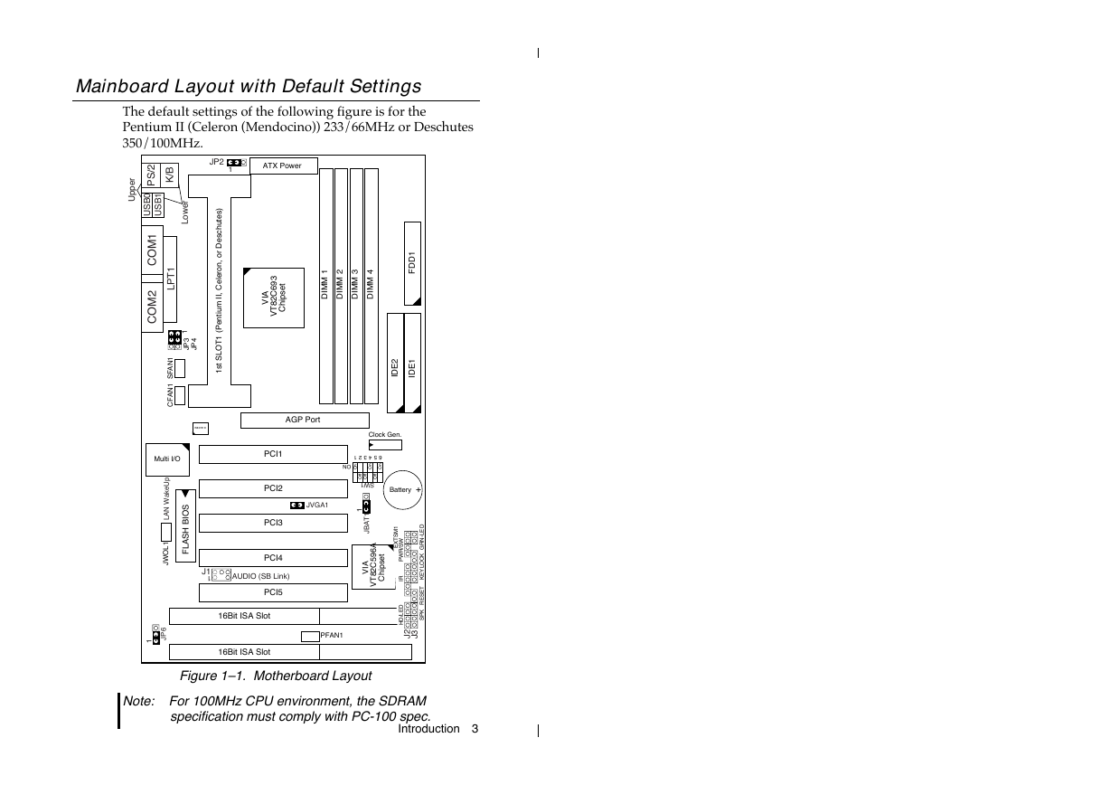
Mainboard Layout with Default Settings
The default settings of the following figure is for the
Pentium II (Celeron (Mendocino)) 233/66MHz or Deschutes
350/100MHz.
JP2
1
ATX Power
)
s
e
t
u
h
c
s
e
D
r
o
,
n
o
r
e
e
C
l
,
I
I
m
u
i
t
n
e
P
(
1
T
O
L
S
t
s
1
A
V
I
t
e
s
p
h
C
i
3
9
6
C
2
8
T
V
1
M
M
D
I
2
M
M
D
I
3
M
M
D
I
4
M
M
D
I
1
D
D
F
2
E
D
I
1
E
D
I
r
e
p
p
U
2
/
S
P
B
K
/
0
B
S
U
1
B
S
U
r
e
w
o
L
1
M
O
C
2
M
O
C
1
T
P
L
1
N
A
F
S
1
N
A
F
C
1
3
P
J
4
P
J
W83781D
AGP Port
Clock Gen.
Multi I/O
I
S
O
B
H
S
A
L
F
p
U
e
k
a
W
N
A
L
1
L
O
W
J
6
P
J
1
PCI1
PCI2
PCI3
PCI4
J1
1
AUDIO (SB Link)
PCI5
16Bit ISA Slot
16Bit ISA Slot
654321
ON
n
O
n
O
n
O
f
f
f
f
O
O
f
f
O
SW1
1
1
T
A
B
J
JVGA1
A
6
9
5
C
2
8
T
V
t
e
s
p
h
C
i
I
A
V
Battery
+
1
M
S
T
X
E
/
W
S
R
W
P
R
I
D
E
L
D
H
/
D
E
L
-
N
R
G
K
C
O
L
Y
E
K
T
E
S
E
R
K
P
S
PFAN1
2
J
3
J
Figure 1–1. Motherboard Layout
Note: For 100MHz CPU environment, the SDRAM
specification must comply with PC-100 spec.
Introduction 3
�
Chapter 2
Hardware Setup
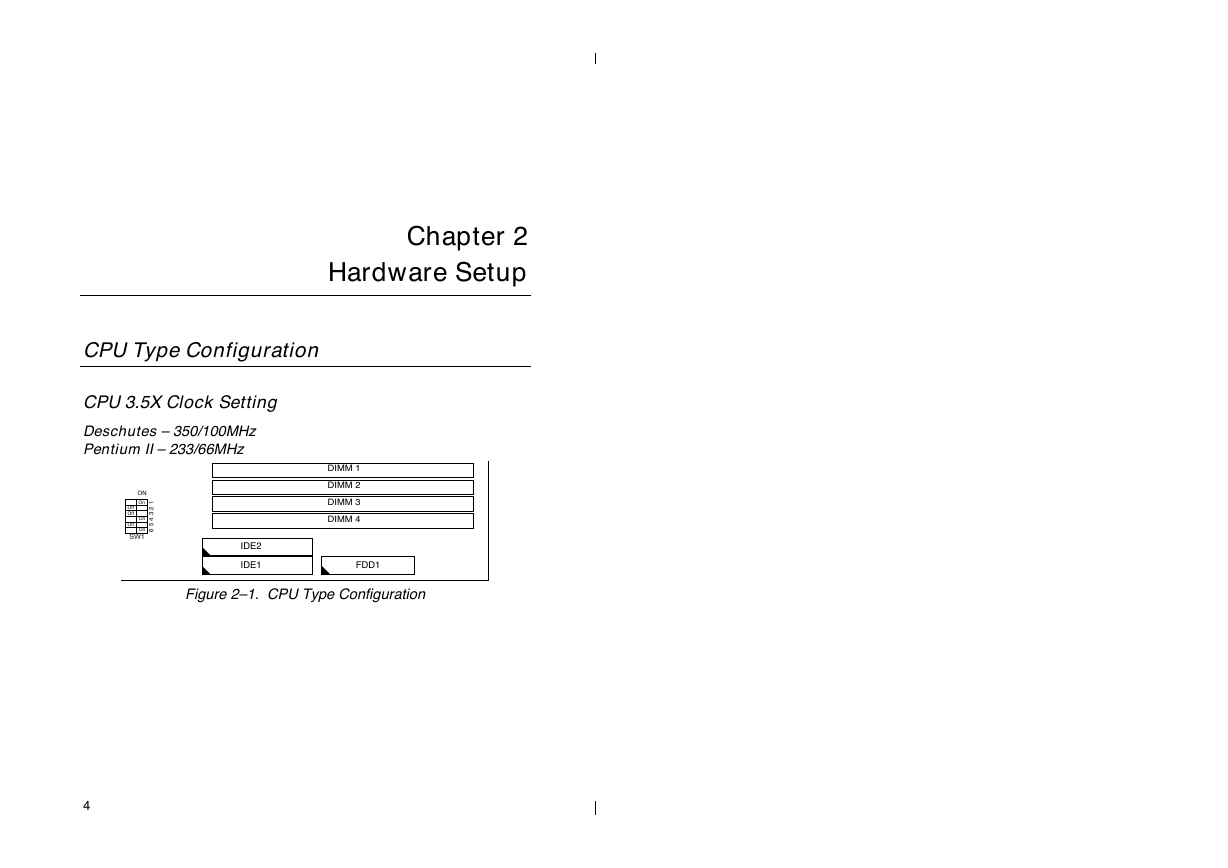
CPU Type Configuration
CPU 3.5X Clock Setting
Deschutes – 350/100MHz
Pentium II – 233/66MHz
ON
On
On
On
SW1
Off
Off
Off
1
2
3
4
5
6
DIMM 1
DIMM 2
DIMM 3
DIMM 4
IDE2
IDE1
FDD1
Figure 2–1. CPU Type Configuration
4
�




 2023年江西萍乡中考道德与法治真题及答案.doc
 2012年重庆南川中考生物真题及答案.doc
 2013年江西师范大学地理学综合及文艺理论基础考研真题.doc
 2020年四川甘孜小升初语文真题及答案I卷.doc
 2020年注册岩土工程师专业基础考试真题及答案.doc
 2023-2024学年福建省厦门市九年级上学期数学月考试题及答案.doc
 2021-2022学年辽宁省沈阳市大东区九年级上学期语文期末试题及答案.doc
 2022-2023学年北京东城区初三第一学期物理期末试卷及答案.doc
 2018上半年江西教师资格初中地理学科知识与教学能力真题及答案.doc
 2012年河北国家公务员申论考试真题及答案-省级.doc
 2020-2021学年江苏省扬州市江都区邵樊片九年级上学期数学第一次质量检测试题及答案.doc
 2022下半年黑龙江教师资格证中学综合素质真题及答案.doc