TELKOMNIKA, Vol.11, No.1, January 2013, pp. 279~286
e-ISSN: 2087-278X
� 279
The Implementation of S-curve Acceleration and
Deceleration Using FPGA
Guangyou Yang*1,2, Zhijian Ye1,2, Yurong Pan1,2 and Zhiyan Ma1,2
1School of Mechanical Engineering, Hubei University of Technology, Wuhan, China
2State Key Lab. Of Digital Manufacturing Equipment & Technology (HUST), Wuhan, China
*corresponding author, e-mail: pekka@126.com
Abstract
This paper analyzes the basic principle of S-curve acceleration and deceleration, and presents an
implementation method of S-curve control algorithm based on FPGA. The S-curve function module
diagram and implementing method of PWM speed adjusting are described in FPGA. The steps of S-curve
speed dissociation module and PWM variable frequency speed control are shown in this paper. High
Performance and Capacity Mixed HDL Simulation software – ModelSim is used to verify the algorithm
Verilog HDL code executed in FPGA. At last, a test experiment utilizing such algorithm mentioned above is
carried out on one x-y working stand. There is a good agreement between simulation and experiment. The
experimental results indicate that the algorithm is simple and reliable enough to meet different application
requirements.
Keyword: FPGA; S-curve; Acceleration/deceleration; PWM.
1. Introduction
Copyright © 2013 Universitas Ahmad Dahlan. All rights reserved.
The speed control of motor acceleration and deceleration is a crucial factor when
high speed and precision position of motor is needed [1], [2]. The common speed controlling
curves are linear, index and S-curve. The flexibility of control system with linear speed control is
poor. It triggers potential problems such as shock and acceleration/deceleration mutations when
the motor start up and acceleration/deceleration phase is over. Therefore, this algorithm is not
suited for a control system which requires high speed and precision. By contrast, the S-curve
algorithm is usually used in many high grade multi-axis motion control systems. It reduces
shock and makes full use of the motor performance by attenuation of the motor deceleration in
start-up stage [3]. In order to improve the real-time performance of motion control system, the
acceleration/deceleration speed control algorithm must be simple [4]. This paper analyzes S-
curve speed control algorithm and realization in FPGA.
2. System structure of S-curve acceleration and deceleration based on FPGA
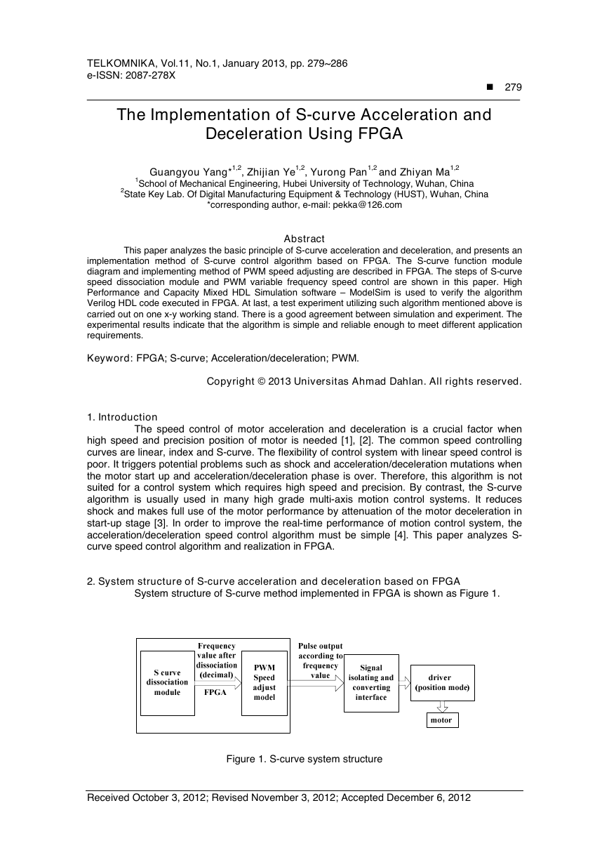
System structure of S-curve method implemented in FPGA is shown as Figure 1.
Figure 1. S-curve system structure
Received October 3, 2012; Revised November 3, 2012; Accepted December 6, 2012
�
280
�
e-ISSN: 2087-278X
The S-curve dissociation module in the Figure 1 extracts several points from continuous
speed-time S-curve and converts those speed value to corresponding frequency value (decimal)
for every point. The more points extracted, the higher precision of S-curve realized in FPGA.
In this paper the motor drive works in position mode, which changes motor speed by
altering the frequency of input signal. Thus, the regulation of motor speed using S-curve
controlling algorithm can be achieved by altering the frequency of speed controlling pulse. In
Figure 1, In order to adjust the speed of motor, the PWM speed regulation model converts
frequency value produced by S-curve module to corresponding frequency pulse output, and
different frequency value has different frequency pulse.
2.1 S curve speed dissociation module
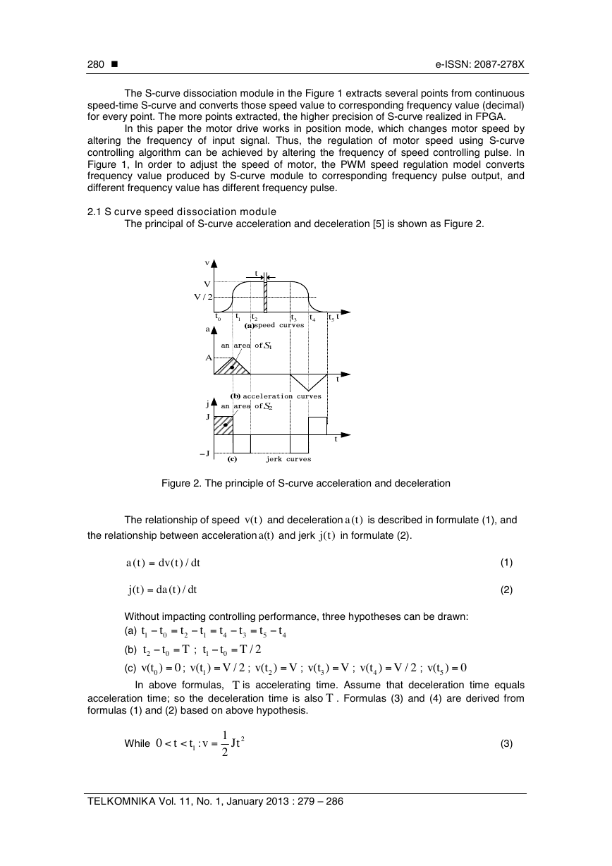
The principal of S-curve acceleration and deceleration [5] is shown as Figure 2.
v
V
/ 2V
a
A
j
J
J-
t
0t
1t
2t
3t
4t
t
5t
t
t
Figure 2. The principle of S-curve acceleration and deceleration
The relationship of speed
( )v t
the relationship between acceleration
and deceleration
( )a t
and jerk
)(tj
( )a t
in formulate (2).
is described in formulate (1), and
)( =
ta
)( =
tj
tdv
/)(
dt
tda
/)(
dt
(1)
(2)
Without impacting controlling performance, three hypotheses can be drawn:
(a)
-=
t
2
T
;
-=
t
t
t
1
0
4
- =
- =
t
t
t
2
0
v t =
V=
0(
) 0
In above formulas,
t
1
t
;
1
1( )
v t
0
(b)
(c)
t
4
t
3
T
/ 2
T
-=
t
5
/ 2
2(
v t
;
is accelerating time. Assume that deceleration time equals
. Formulas (3) and (4) are derived from
v t =
5( ) 0
3( )
v t
V=
V=
V=
4(
v t
/ 2
;
;
)
;
)
acceleration time; so the deceleration time is also
formulas (1) and (2) based on above hypothesis.
T
While
< <
0 t
v =
t
1
:
1
2
2
Jt
(3)
TELKOMNIKA Vol. 11, No. 1, January 2013 : 279 – 286
-
D
�
TELKOMNIKA
While
t
1
< <
t
=
t
2
:
v
e-ISSN: 2087-278X
1
4
J
(4
tT
2
2
t
T
2
)
�
281
(4)
=
J
4 /
V T
2
, utilizing counter/timer to get running time:
t n
c
t
, and it is usually
is the value of counter. Utilizing formulas (1), (2), (3) and (4), the final
updates the speed and corresponding output frequency at every cycle
microsecond level,
speed calculating formulas (5) and (6) can be derived as follows:
. This algorithm
cn
t
= D
While
While
< <
0 t
=
t
1
:
v
2
2
V t n
c
2
/
T
2
< <
t
t
1
t
2
:
=
v V T
/
2
(4
T tn T
c
2
2
2
t n
c
T
2
)
(5)
(6)
v
The value of
on every point of the S-curve can be derived from formulas (5) and
(6). Then decimal frequency value corresponding to different speed can be derived from the
(the unit of is um/s and
is HZ,
is a constant and it
formula of speed and frequency
has different value in different system, for experimental system,
is set to 20) [6]. Figure 3 is
S-curve’s instantiation figure in FPGA.
kv=
f
k
k
v
f
Figure 3. The S-curve model instantiation figure in FPGA
2.2 PWM speed regulation model
f
Frequency value
derived from corresponding speed value needs to be converted to
corresponding pulse output. While the new type of power electronic power components are
appearing daily, Pulse Width Modulation (PWM) control ways become mainstream [7], [8] by
using all-controlling switch power components. In this paper, motor driver works in position
mode and can adjust motor speed by changing the frequency of PWM signal (keeping duty ratio
unchanged). Figure 4 is the basic model of PWM.
Figure 4. The basic model of pulse width modulation
The Implementation of S-curve Acceleration and Deceleration Using FPGA (Guangyou Yang)
D
-
-
·
D
D
-
D
-
�
282
�
e-ISSN: 2087-278X
In Figure 4, circulation counter count extern sampling pulse and its value is added 1 at
every sampling cycle. The comparator will compare counter value with value loaded in buffer
register. When the output value of counter is less than half of the counting value of pulse cycle,
the output of comparator stays low level. When they are equal, the output changes into high
level. When the output value is equal to the counting value of pulse cycle, the output level is
changed from high to low. Thus a pulse cycle is over. In every cycle of comparator’s counting,
the comparator outputs different frequency pulse due to different pulse cycles of modulating
signal from input, so that the speed regulation of motor can be achieved under the position
mode of motor drive.
Figure 5 is the instantiation figure of PWM model. This model designs a common
controlled frequency division machine, which can meet various requirement described above
using hardware programming language Verilog HDL [9] on Quartus-II [10] researching platform.
Compared to Figure 4, reset is reset signal, clk is input clock, cycle is cycle value of pulse (it is
the value of
derived from 2.1) and clkout is PWM output signal.
f
reset
clk
cy cle[31:0]
INPUT
VCC
INPUT
VCC
INPUT
VCC
PWM_Module
reset
clk
cy cle[31..0]
inst
clkout
OUTPUT
clkout
Figure 5. Instantiation figure of PWM model in FPGA
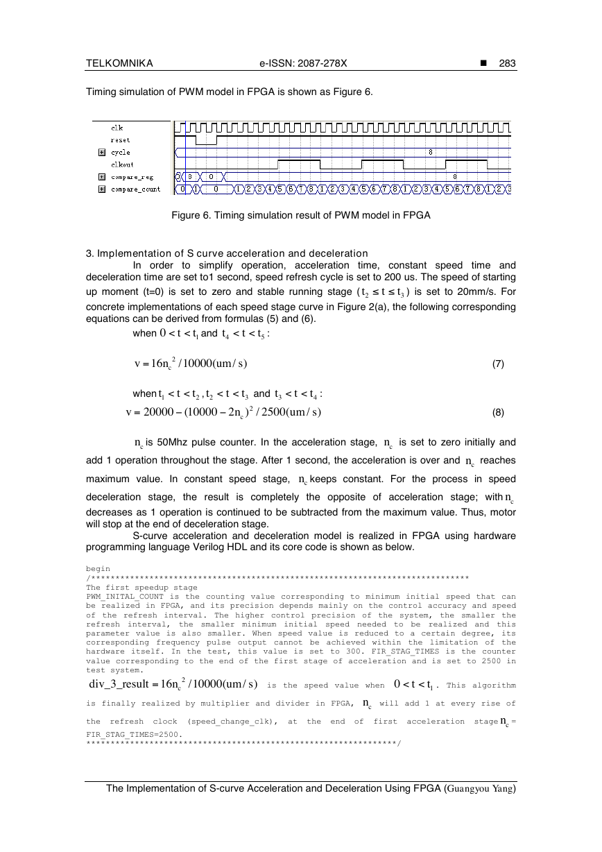
PWM model is realized in FPGA using hardware programming language Verilog HDL and its
core code is shown as below.
wire[31:0] duty; // occupy proportion
assign duty = compare_reg/2; //occupy proportion is always 50%
reg[31:0] compare_count;//count of pulse
//regcompare_reg_refresh_flag;
always @ (negedge reset or posedgeclk)
begin
if(!reset)
begin
clkout<= 0;
compare_count<= 0;
end
else if (compare_reg != 0)
/* when output value of comparator is half of cycle value ofpulse, the output level
begin
of comparator changes to high level.*/
/* when output value of comparator is equal to cycle value of pulse, the output level
begin
clkout<= 1;
compare_count<= compare_count + 1;
end
if(compare_count == duty)
of comparator changes from high to low. */
else if (compare_count == compare_reg)
else
begin
clkout<= 0;
compare_count<= 1;
end
compare_count<= compare_count + 1;
begin
compare_count<= 0;
clkout<= 0;
end
end
else
end
TELKOMNIKA Vol. 11, No. 1, January 2013 : 279 – 286
�
TELKOMNIKA
e-ISSN: 2087-278X
�
283
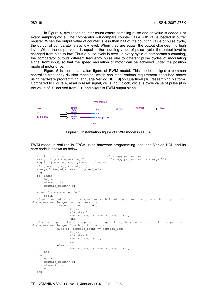
Timing simulation of PWM model in FPGA is shown as Figure 6.
Figure 6. Timing simulation result of PWM model in FPGA
3. Implementation of S curve acceleration and deceleration
In order
to simplify operation, acceleration
time and
deceleration time are set to1 second, speed refresh cycle is set to 200 us. The speed of starting
up moment (t=0) is set to zero and stable running stage (
) is set to 20mm/s. For
concrete implementations of each speed stage curve in Figure 2(a), the following corresponding
equations can be derived from formulas (5) and (6).
time, constant speed
t
t
t
2
3
< <
0 t
t
1
and
t
4
< <
t
t
5
:
=
when
v
when
=
v
16
2
n
c
/10000(
/ )
um s
< <
t
t
1
t
2
,
t
2
< <
t
t
3
20000 (10000 2 ) / 2500(
n
c
t
3
and
2
< <
t
t
:
4
/ )
um s
(7)
(8)
cn
is 50Mhz pulse counter. In the acceleration stage,
cn
is set to zero initially and
add 1 operation throughout the stage. After 1 second, the acceleration is over and
cn
reaches
maximum value. In constant speed stage,
keeps constant. For the process in speed
cn
deceleration stage, the result is completely the opposite of acceleration stage; with
decreases as 1 operation is continued to be subtracted from the maximum value. Thus, motor
will stop at the end of deceleration stage.
cn
S-curve acceleration and deceleration model is realized in FPGA using hardware
programming language Verilog HDL and its core code is shown as below.
begin
/******************************************************************************
The first speedup stage
PWM_INITAL_COUNT is the counting value corresponding to minimum initial speed that can
be realized in FPGA, and its precision depends mainly on the control accuracy and speed
of the refresh interval. The higher control precision of the system, the smaller the
refresh interval, the smaller minimum initial speed needed to be realized and this
parameter value is also smaller. When speed value is reduced to a certain degree, its
corresponding frequency pulse output cannot be achieved within the limitation of the
hardware itself. In the test, this value is set to 300. FIR_STAG_TIMES is the counter
value corresponding to the end of the first stage of acceleration and is set to 2500 in
test system.
=
div_3_result 16
is the speed value when
. This algorithm
/10000(
/ )
um s
< <
0 t
2
cn
t
1
is finally realized by multiplier and divider in FPGA,
cn
will add 1 at every rise of
the refresh clock (speed_change_clk), at the end of first acceleration stage
cn
=
FIR_STAG_TIMES=2500.
****************************************************************/
The Implementation of S-curve Acceleration and Deceleration Using FPGA (Guangyou Yang)
£
£
-
-
�
284
�
e-ISSN: 2087-278X
v <= div_3_result;
if (s_count>= PWM_INITAL_COUNT &&s_count<= FIR_STAG_TIMES)
begin
end
/*************************************************************
The second speedup stage
TOTAL_SPEEDUP_TIMES is the counting value corresponding to the end of the second
system.
acceleration
=
< <
div_1_quo
20000 (10000 2 ) / 2500(
is the speed value when
/ )
um s
is
2
stage
5000
test
set
and
in
to
t
t
cn
t
1
2
.This algorithm is finally realized by multiplier and divider in FPGA,
cn
will add 1 at
every rise of the refresh clock(speed_change_clk),
cn
=TOTAL_SPEEDUP_TIMES=5000 at the
stage(the
deceleration
begin
end
v <= 20000 - div_1_quo;
if(s_count> FIR_STAG_TIMES &&s_count<= TOTAL_SPEEDUP_TIMES )
end of second acceleration stage, and will keep its value not changed in constant speed
stage.
*************************************************************/
/*************************************************************
The first speeddown stage
The first stage of deceleration is an inverse process of the second stage of
acceleration. FIRST_SPEEDDOWN_STAR_POINT is counting value corresponding to the moment
when
over,
SECON_SPEEDDOWN_STAR_POINT is the counting value corresponding to the moment when first
deceleration stage(the moment at the beginning of second deceleration) is over.
*************************************************************/
if(s_count>=FIRST_SPEEDDOWN_STAR_POINT&&s_count<=SECON_SPEEDDOWN_STAR_POINT)
/*************************************************************
The second speeddown stage
The second deceleration stage is a inverse process of the first acceleration stage.
S_CARVE_END_POINT is the speed value corresponding to the moment when S curve algorithm
is running over
***********************************************************/
if (s_count>SECON_SPEEDDOWN_STAR_POINT &&s_count<= S_CARVE_END_POINT)
begin
end
v <= 20000 - div_1_quo;
begin
end
v <= div_3_result;
constant
stage)
end
the
of
is
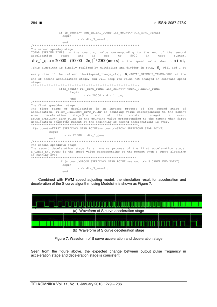
Combined with PWM speed adjusting model, the simulation result for acceleration and
deceleration of the S curve algorithm using Modelsim is shown as Figure 7.
(a) Waveform of S curve acceleration stage
(b) Waveform of S curve deceleration stage
Figure 7. Waveform of S curve acceleration and deceleration stage
Seen from the figure above, the expected change between output pulse frequency in
acceleration stage and deceleration stage is consistent.
TELKOMNIKA Vol. 11, No. 1, January 2013 : 279 – 286
-
-
�
TELKOMNIKA
4. Application experiment
e-ISSN: 2087-278X
�
285
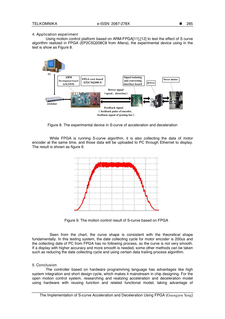
Using motion control platform based on ARM-FPGA[11],[12] to test the effect of S curve
algorithm realized in FPGA (EP2C5Q208C8 from Altera), the experimental device using in the
test is show as Figure 8.
ARM
Development board
(s3c2410)
FPGA core board
EP2C5Q208C8
Signal isolating
and converting
interface board
driver
Sever motor
switcher
Driver signal
speed direction
Feedback signal
feedback pulse of encoder,
feedback signal of grating bar
Figure 8. The experimental device in S-curve of acceleration and deceleration
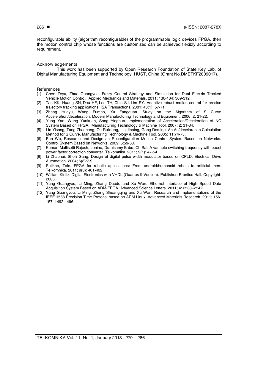
While FPGA is running S-curve algorithm, it is also collecting the data of motor
encoder at the same time, and those data will be uploaded to PC through Ethernet to display.
The result is shown as figure 9.
Figure 9. The motion control result of S-curve based on FPGA
Seen from the chart, the curve shape is consistent with the theoretical shape
fundamentally. In this testing system, the date collecting cycle for motor encoder is 200us and
the collecting date of PC from FPGA has no following process, so the curve is not very smooth.
If a display with higher accuracy and more smooth is needed, some other methods can be taken
such as reducing the date collecting cycle and using certain data trailing process algorithm.
5. Conclusion
The controller based on hardware programming language has advantages like high
system integration and short design cycle, which makes it mainstream in chip designing. For the
open motion control system, researching and realizing acceleration and deceleration model
using hardware with reusing function and related functional model, taking advantage of
The Implementation of S-curve Acceleration and Deceleration Using FPGA (Guangyou Yang)
�
286
�
e-ISSN: 2087-278X
reconfigurable ability (algorithm reconfigurable) of the programmable logic devices FPGA, then
the motion control chip whose functions are customized can be achieved flexibly according to
requirement.
Acknowledgements
This work has been supported by Open Research Foundation of State Key Lab. of
Digital Manufacturing Equipment and Technology, HUST, China (Grant No.DMETKF2009017).
References
[1] Chen Zeyu, Zhao Guangyao. Fuzzy Control Strategy and Simulation for Dual Electric Tracked
Vehicle Motion Control. Applied Mechanics and Materials. 2011; 130-134: 309-312.
[2] Tan KK, Huang SN, Dou HF, Lee TH, Chin SJ, Lim SY. Adaptive robust motion control for precise
trajectory tracking applications. ISA Transactions. 2001; 40(1); 57-71.
[3] Zhang Huayu, Wang Fumao, Xu Fangquan. Study on
the Algorithm of S Curve
Acceleration/deceleration. Modern Manufacturing Technology and Equipment. 2006; 2: 21-22.
[4] Yang Yan, Wang Yunkuan, Song Yinghua. Implementation of Acceleration/Deceleration of NC
System Based on FPGA. Manufacturing Technology & Machine Tool. 2007; 2: 31-34.
[5] Lin Yisong, Tang Zhaohong, Ou Ruixiang, Lin Jinping, Gong Deming. An Ac/decelaration Calculation
Method for S Curve. Manufacturing Technology & Machine Tool. 2005; 11:74-75.
[6] Pan Wu, Research and Design an Reconfiguration Motion Control System Based on Networks.
Control System Based on Networks. 2009; 5:59-60.
[7] Kumar, Mallisetti Rajesh, Lenine, Duraisamy Babu, Ch Sai. A variable switching frequency with boost
power factor correction converter. Telkomnika. 2011; 9(1): 47-54.
[8] Li Zhaohui, Shen Gang. Design of digital pulse width modulator based on CPLD. Electrical Drive
Automation. 2004; 6(3):7-9.
[9] Sutikno, Tole. FPGA for robotic applications: From android/humanoid robots to artificial men.
Telkomnika. 2011; 9(3): 401-402.
[10] William Kleitz. Digital Electronics with VHDL (Quartus II Version). Publisher: Prentice Hall. Copyright:
2006.
[11] Yang Guangyou, Li Ming, Zhang Daode and Xu Wan. Ethernet Interface of High Speed Data
Acquisition System Based on ARM-FPGA. Advanced Science Letters. 2011; 4: 2538–2542.
[12] Yang Guangyou, Li Ming, Zhang Shuangqing and Xu Wan. Research and implementations of the
IEEE 1588 Precision Time Protocol based on ARM-Linux. Advanced Materials Research. 2011; 156-
157: 1492-1496.
TELKOMNIKA Vol. 11, No. 1, January 2013 : 279 – 286
�



 2023年江西萍乡中考道德与法治真题及答案.doc
 2012年重庆南川中考生物真题及答案.doc
 2013年江西师范大学地理学综合及文艺理论基础考研真题.doc
 2020年四川甘孜小升初语文真题及答案I卷.doc
 2020年注册岩土工程师专业基础考试真题及答案.doc
 2023-2024学年福建省厦门市九年级上学期数学月考试题及答案.doc
 2021-2022学年辽宁省沈阳市大东区九年级上学期语文期末试题及答案.doc
 2022-2023学年北京东城区初三第一学期物理期末试卷及答案.doc
 2018上半年江西教师资格初中地理学科知识与教学能力真题及答案.doc
 2012年河北国家公务员申论考试真题及答案-省级.doc
 2020-2021学年江苏省扬州市江都区邵樊片九年级上学期数学第一次质量检测试题及答案.doc
 2022下半年黑龙江教师资格证中学综合素质真题及答案.doc