GPUs - Graphics Processing Units
Minh Tri Do Dinh
Minh.Do-Dinh@student.uibk.ac.at
Vertiefungsseminar Architektur von Prozessoren, SS 2008
Institute of Computer Science, University of Innsbruck
July 7, 2008
This paper is meant to provide a closer look at modern Graphics Processing Units. It explores
their architecture and underlying design principles, using chips from Nvidia’s ”Geforce” series as
examples.
1 Introduction
Before we dive into the architectural details of some example GPUs, we’ll have a look at some basic concepts
of graphics processing and 3D graphics, which will make it easier for us to understand the functionality of
GPUs
1.1 What is a GPU?
A GPU (Graphics Processing Unit) is essentially a dedicated hardware device that is responsible for trans-
lating data into a 2D image formed by pixels. In this paper, we will focus on the 3D graphics, since that is
what modern GPUs are mainly designed for.
1.2 The anatomy of a 3D scene
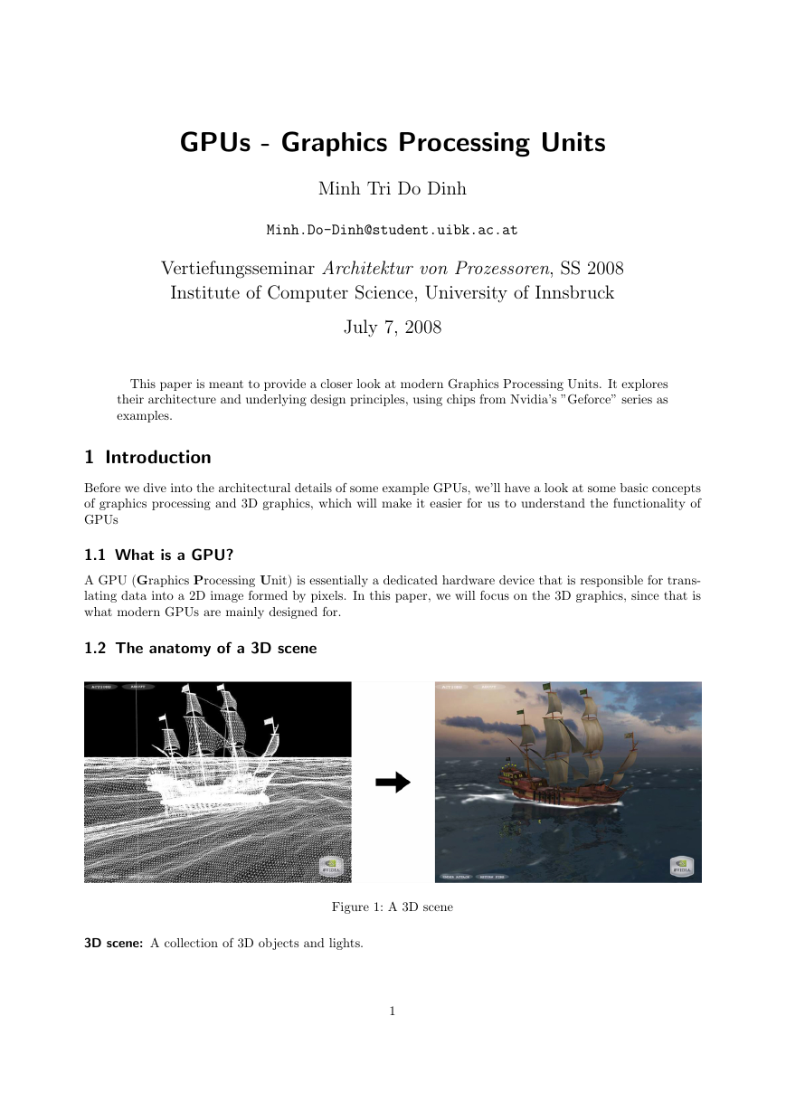
3D scene: A collection of 3D objects and lights.
Figure 1: A 3D scene
1
�
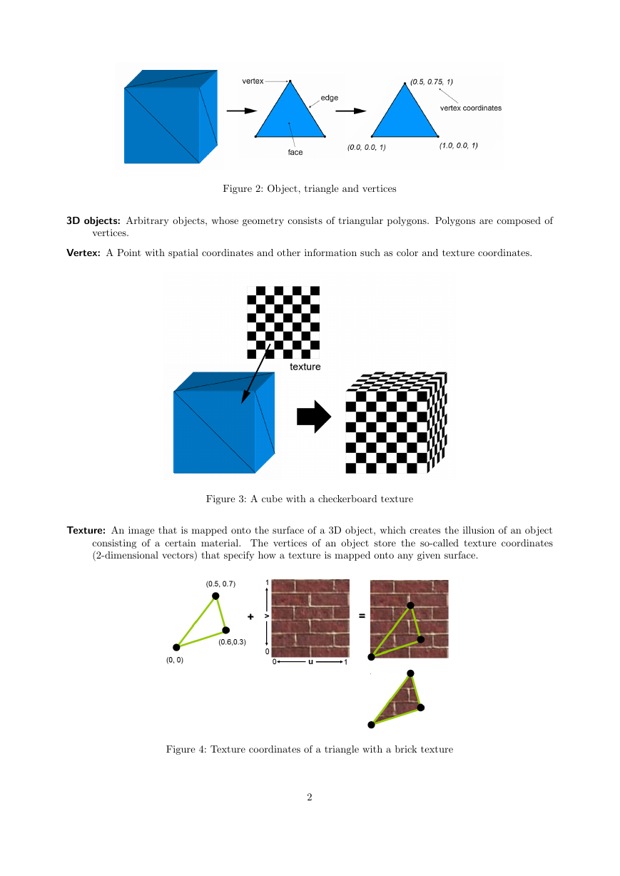
Figure 2: Object, triangle and vertices
3D objects: Arbitrary objects, whose geometry consists of triangular polygons. Polygons are composed of
vertices.
Vertex: A Point with spatial coordinates and other information such as color and texture coordinates.
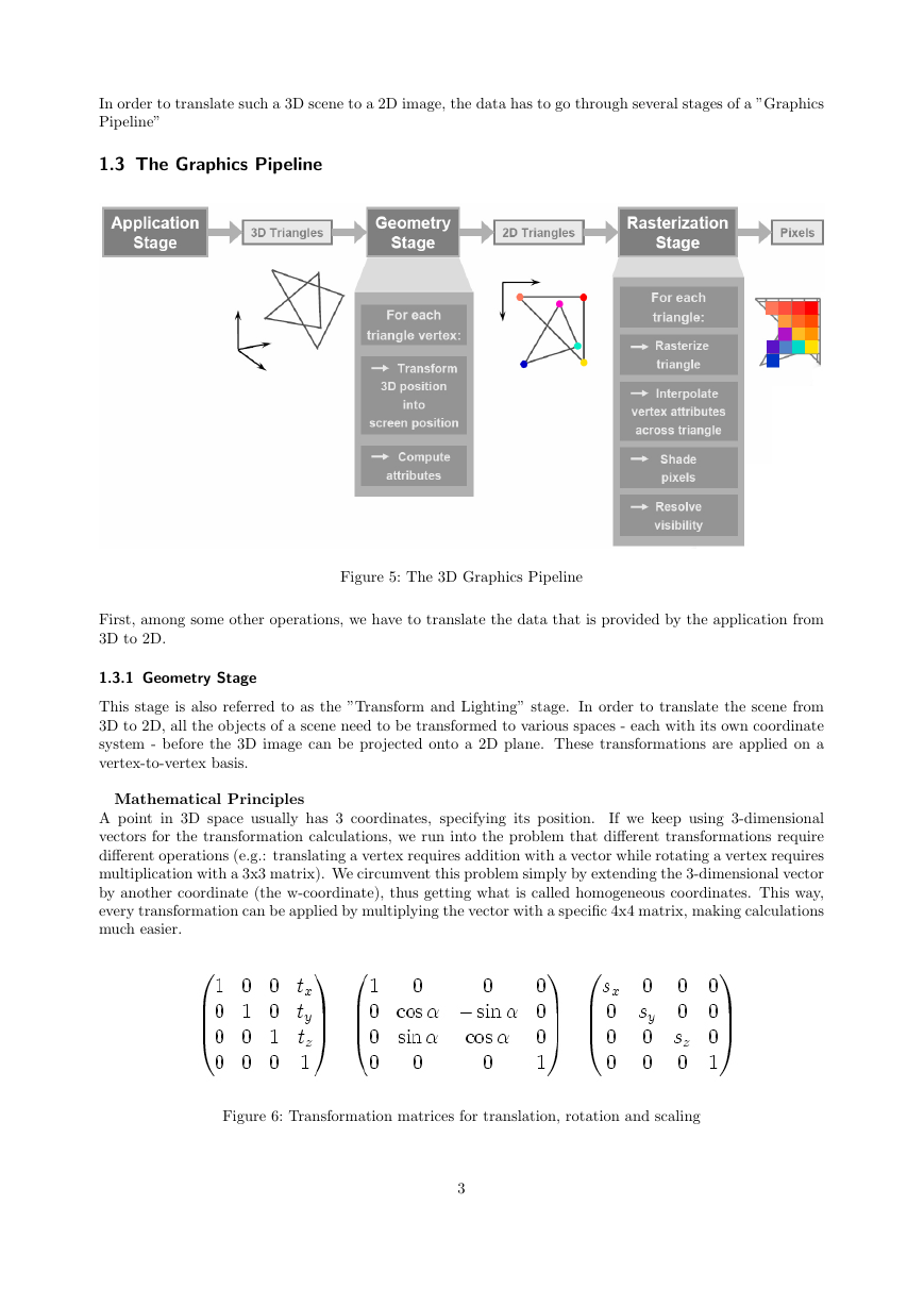
Figure 3: A cube with a checkerboard texture
Texture: An image that is mapped onto the surface of a 3D object, which creates the illusion of an object
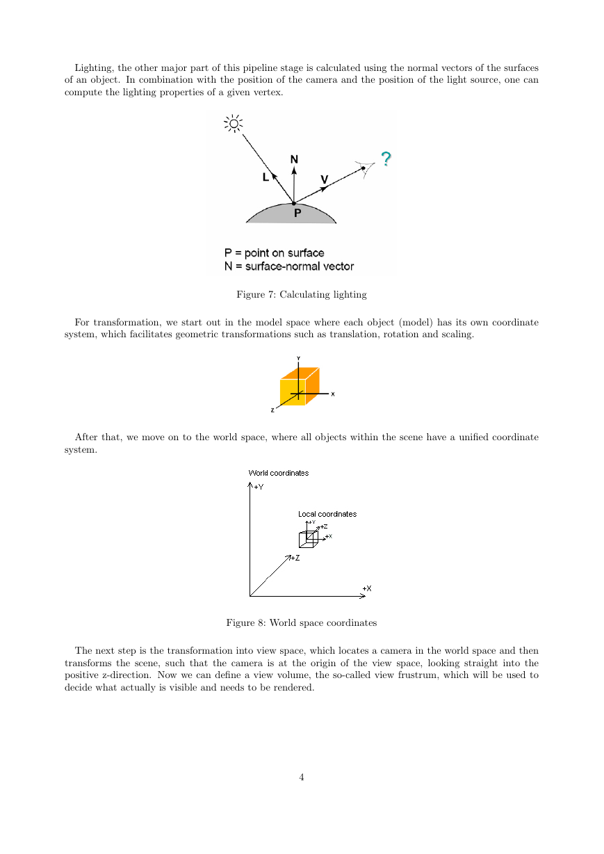
consisting of a certain material. The vertices of an object store the so-called texture coordinates
(2-dimensional vectors) that specify how a texture is mapped onto any given surface.
Figure 4: Texture coordinates of a triangle with a brick texture
2
�
In order to translate such a 3D scene to a 2D image, the data has to go through several stages of a ”Graphics
Pipeline”
1.3 The Graphics Pipeline
Figure 5: The 3D Graphics Pipeline
First, among some other operations, we have to translate the data that is provided by the application from
3D to 2D.
1.3.1 Geometry Stage
This stage is also referred to as the ”Transform and Lighting” stage. In order to translate the scene from
3D to 2D, all the objects of a scene need to be transformed to various spaces - each with its own coordinate
system - before the 3D image can be projected onto a 2D plane. These transformations are applied on a
vertex-to-vertex basis.
Mathematical Principles
If we keep using 3-dimensional
A point in 3D space usually has 3 coordinates, specifying its position.
vectors for the transformation calculations, we run into the problem that different transformations require
different operations (e.g.: translating a vertex requires addition with a vector while rotating a vertex requires
multiplication with a 3x3 matrix). We circumvent this problem simply by extending the 3-dimensional vector
by another coordinate (the w-coordinate), thus getting what is called homogeneous coordinates. This way,
every transformation can be applied by multiplying the vector with a specific 4x4 matrix, making calculations
much easier.
Figure 6: Transformation matrices for translation, rotation and scaling
3
�
Lighting, the other major part of this pipeline stage is calculated using the normal vectors of the surfaces
of an object. In combination with the position of the camera and the position of the light source, one can
compute the lighting properties of a given vertex.
Figure 7: Calculating lighting
For transformation, we start out in the model space where each object (model) has its own coordinate
system, which facilitates geometric transformations such as translation, rotation and scaling.
After that, we move on to the world space, where all objects within the scene have a unified coordinate
system.
Figure 8: World space coordinates
The next step is the transformation into view space, which locates a camera in the world space and then
transforms the scene, such that the camera is at the origin of the view space, looking straight into the
positive z-direction. Now we can define a view volume, the so-called view frustrum, which will be used to
decide what actually is visible and needs to be rendered.
4
�
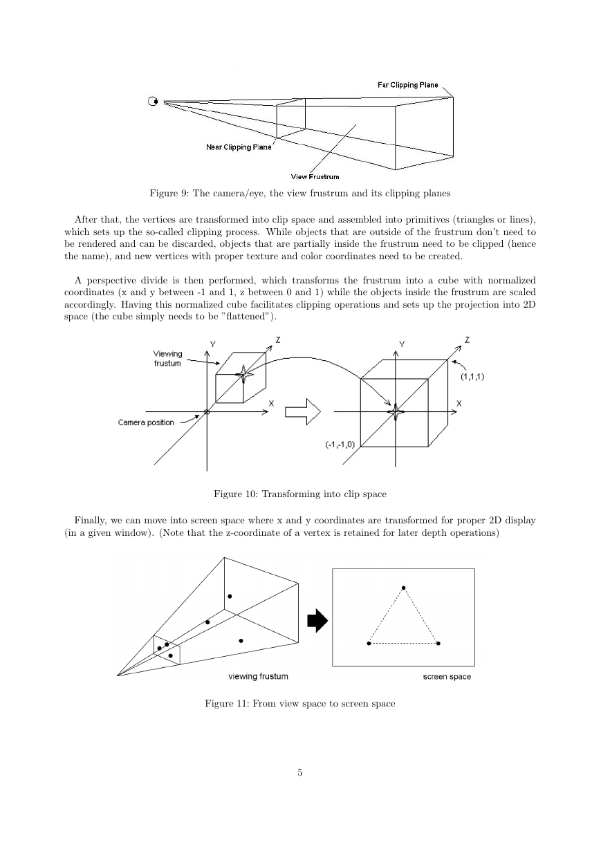
Figure 9: The camera/eye, the view frustrum and its clipping planes
After that, the vertices are transformed into clip space and assembled into primitives (triangles or lines),
which sets up the so-called clipping process. While objects that are outside of the frustrum don’t need to
be rendered and can be discarded, objects that are partially inside the frustrum need to be clipped (hence
the name), and new vertices with proper texture and color coordinates need to be created.
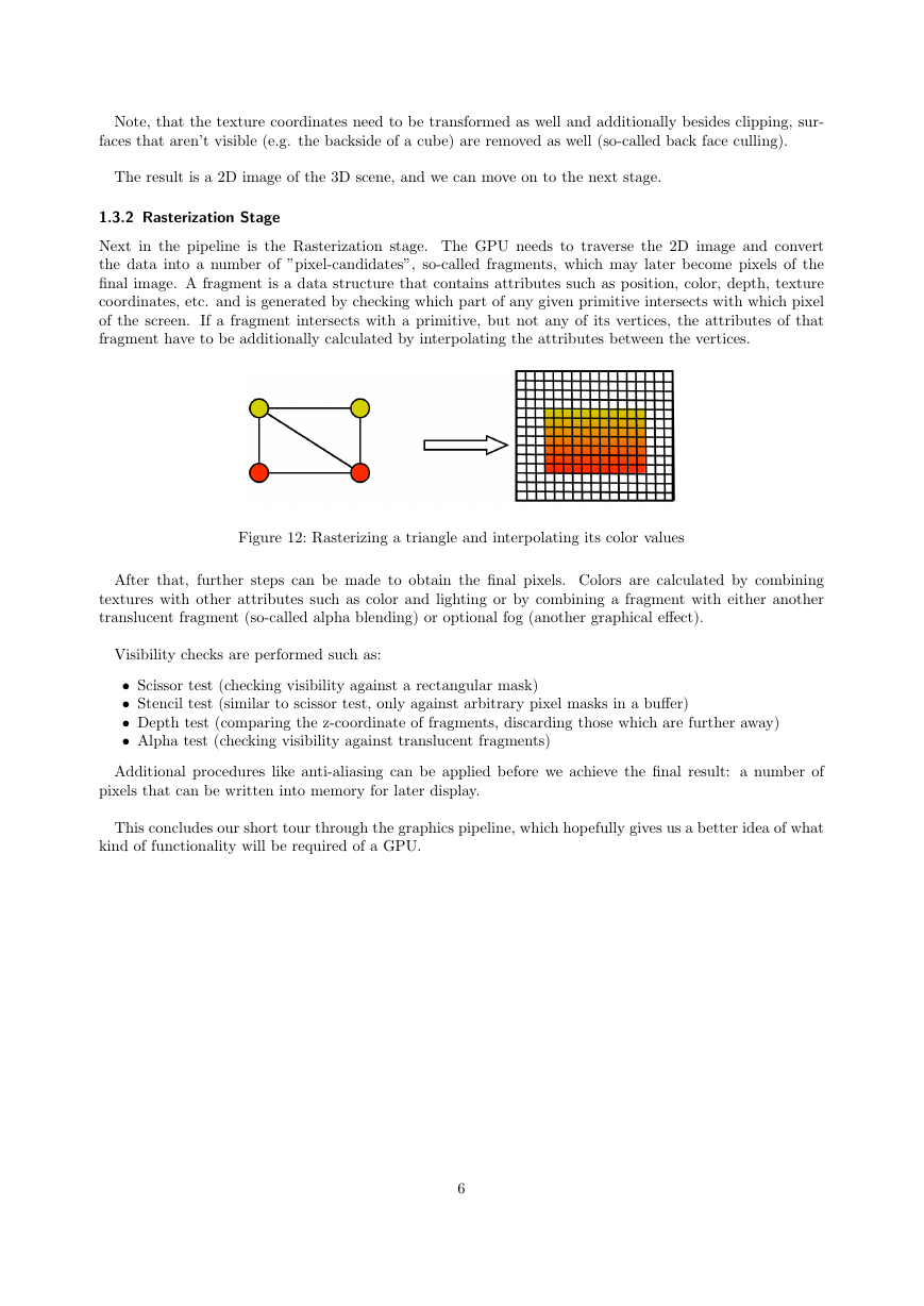
A perspective divide is then performed, which transforms the frustrum into a cube with normalized
coordinates (x and y between -1 and 1, z between 0 and 1) while the objects inside the frustrum are scaled
accordingly. Having this normalized cube facilitates clipping operations and sets up the projection into 2D
space (the cube simply needs to be ”flattened”).
Figure 10: Transforming into clip space
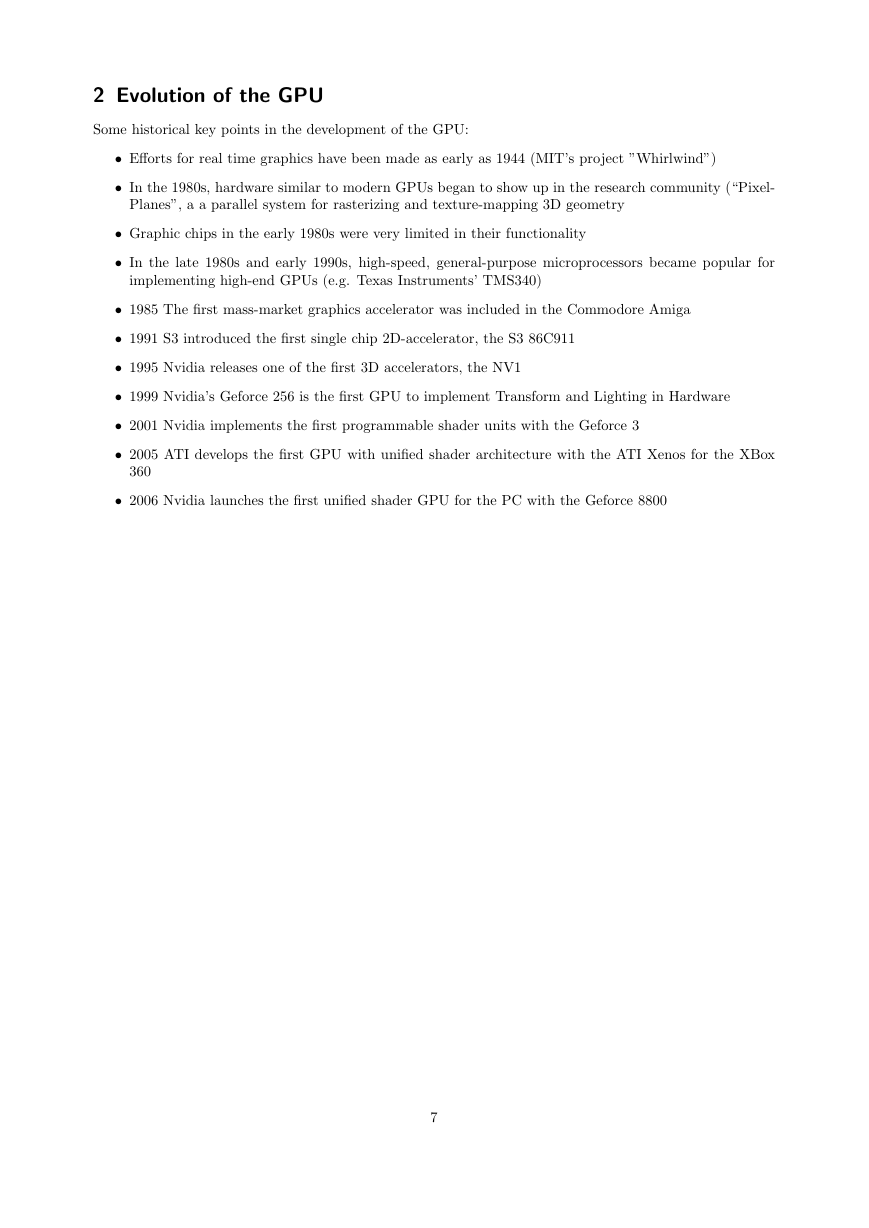
Finally, we can move into screen space where x and y coordinates are transformed for proper 2D display
(in a given window). (Note that the z-coordinate of a vertex is retained for later depth operations)
Figure 11: From view space to screen space
5
�
Note, that the texture coordinates need to be transformed as well and additionally besides clipping, sur-
faces that aren’t visible (e.g. the backside of a cube) are removed as well (so-called back face culling).
The result is a 2D image of the 3D scene, and we can move on to the next stage.
1.3.2 Rasterization Stage
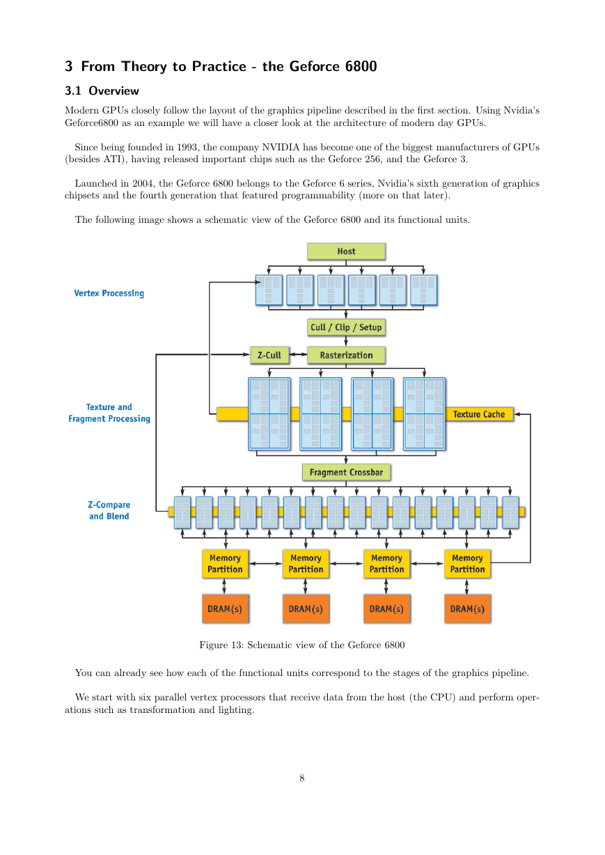
Next in the pipeline is the Rasterization stage. The GPU needs to traverse the 2D image and convert
the data into a number of ”pixel-candidates”, so-called fragments, which may later become pixels of the
final image. A fragment is a data structure that contains attributes such as position, color, depth, texture
coordinates, etc. and is generated by checking which part of any given primitive intersects with which pixel
of the screen. If a fragment intersects with a primitive, but not any of its vertices, the attributes of that
fragment have to be additionally calculated by interpolating the attributes between the vertices.
Figure 12: Rasterizing a triangle and interpolating its color values
After that, further steps can be made to obtain the final pixels. Colors are calculated by combining
textures with other attributes such as color and lighting or by combining a fragment with either another
translucent fragment (so-called alpha blending) or optional fog (another graphical effect).
Visibility checks are performed such as:
• Scissor test (checking visibility against a rectangular mask)
• Stencil test (similar to scissor test, only against arbitrary pixel masks in a buffer)
• Depth test (comparing the z-coordinate of fragments, discarding those which are further away)
• Alpha test (checking visibility against translucent fragments)
Additional procedures like anti-aliasing can be applied before we achieve the final result: a number of
pixels that can be written into memory for later display.
This concludes our short tour through the graphics pipeline, which hopefully gives us a better idea of what
kind of functionality will be required of a GPU.
6
�
2 Evolution of the GPU
Some historical key points in the development of the GPU:
• Efforts for real time graphics have been made as early as 1944 (MIT’s project ”Whirlwind”)
• In the 1980s, hardware similar to modern GPUs began to show up in the research community (“Pixel-
Planes”, a a parallel system for rasterizing and texture-mapping 3D geometry
• Graphic chips in the early 1980s were very limited in their functionality
• In the late 1980s and early 1990s, high-speed, general-purpose microprocessors became popular for
implementing high-end GPUs (e.g. Texas Instruments’ TMS340)
• 1985 The first mass-market graphics accelerator was included in the Commodore Amiga
• 1991 S3 introduced the first single chip 2D-accelerator, the S3 86C911
• 1995 Nvidia releases one of the first 3D accelerators, the NV1
• 1999 Nvidia’s Geforce 256 is the first GPU to implement Transform and Lighting in Hardware
• 2001 Nvidia implements the first programmable shader units with the Geforce 3
• 2005 ATI develops the first GPU with unified shader architecture with the ATI Xenos for the XBox
360
• 2006 Nvidia launches the first unified shader GPU for the PC with the Geforce 8800
7
�
3 From Theory to Practice - the Geforce 6800
3.1 Overview
Modern GPUs closely follow the layout of the graphics pipeline described in the first section. Using Nvidia’s
Geforce6800 as an example we will have a closer look at the architecture of modern day GPUs.
Since being founded in 1993, the company NVIDIA has become one of the biggest manufacturers of GPUs
(besides ATI), having released important chips such as the Geforce 256, and the Geforce 3.
Launched in 2004, the Geforce 6800 belongs to the Geforce 6 series, Nvidia’s sixth generation of graphics
chipsets and the fourth generation that featured programmability (more on that later).
The following image shows a schematic view of the Geforce 6800 and its functional units.
Figure 13: Schematic view of the Geforce 6800
You can already see how each of the functional units correspond to the stages of the graphics pipeline.
We start with six parallel vertex processors that receive data from the host (the CPU) and perform oper-
ations such as transformation and lighting.
8
�


 2023年江西萍乡中考道德与法治真题及答案.doc
 2012年重庆南川中考生物真题及答案.doc
 2013年江西师范大学地理学综合及文艺理论基础考研真题.doc
 2020年四川甘孜小升初语文真题及答案I卷.doc
 2020年注册岩土工程师专业基础考试真题及答案.doc
 2023-2024学年福建省厦门市九年级上学期数学月考试题及答案.doc
 2021-2022学年辽宁省沈阳市大东区九年级上学期语文期末试题及答案.doc
 2022-2023学年北京东城区初三第一学期物理期末试卷及答案.doc
 2018上半年江西教师资格初中地理学科知识与教学能力真题及答案.doc
 2012年河北国家公务员申论考试真题及答案-省级.doc
 2020-2021学年江苏省扬州市江都区邵樊片九年级上学期数学第一次质量检测试题及答案.doc
 2022下半年黑龙江教师资格证中学综合素质真题及答案.doc