logo资料库

pg105-cordic-Xilinx.pdf

第1页 / 共66页
第2页 / 共66页
第3页 / 共66页
第4页 / 共66页
第5页 / 共66页
第6页 / 共66页
第7页 / 共66页
第8页 / 共66页
资料共66页,剩余部分请下载后查看
CORDIC v6.0
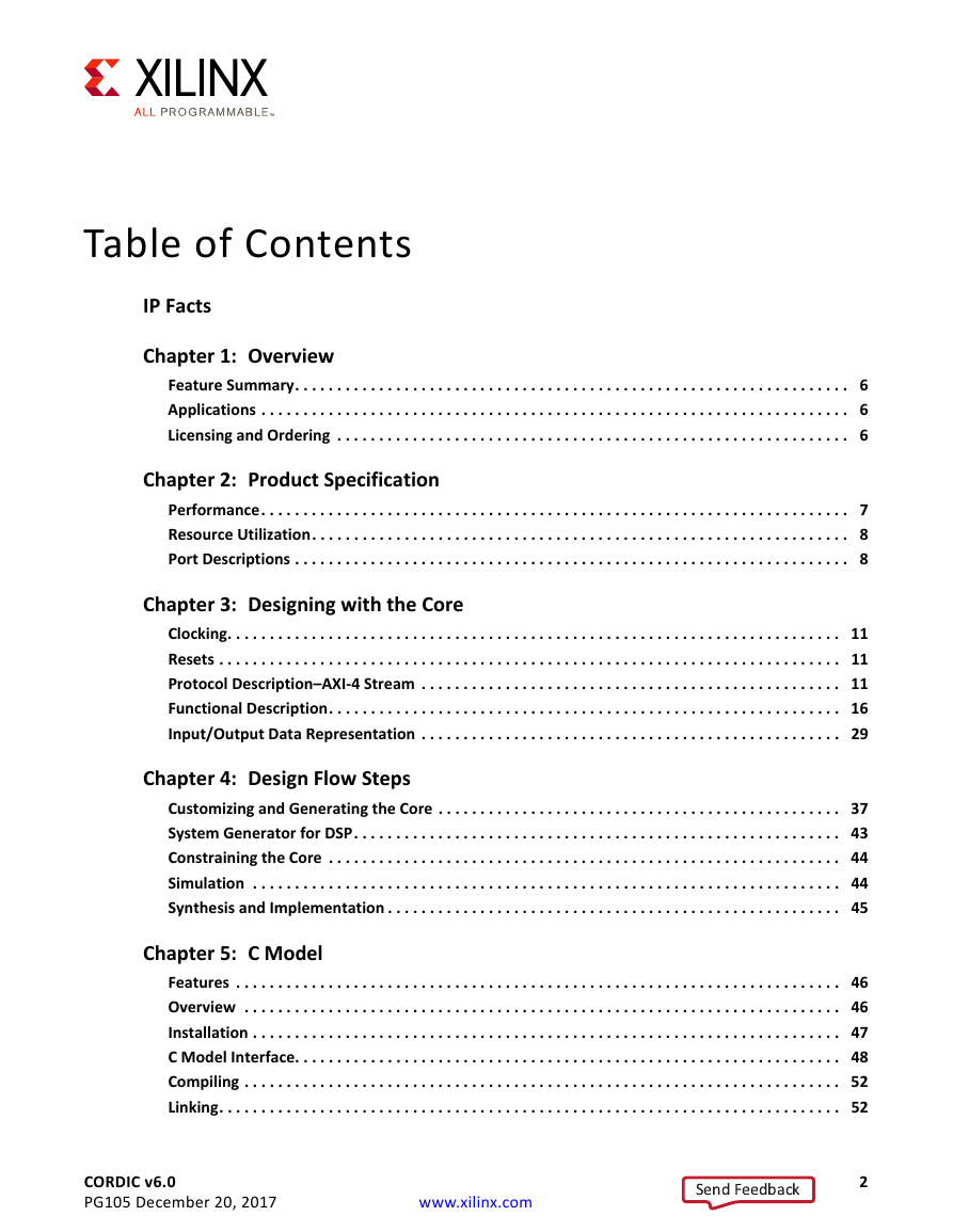
Table of Contents
IP Facts
Ch. 1: Overview
Feature Summary
Applications
Licensing and Ordering
Ch. 2: Product Specification
Performance
Parallel Architectural Configuration
Word Serial Architectural Configuration
Resource Utilization
Port Descriptions
Data Inputs and Outputs
Ch. 3: Designing with the Core
Clocking
Resets
Protocol Description–AXI-4 Stream
Basic Handshake
Non Blocking Mode
Blocking Mode
TDATA Packing
TDATA Structure for Cartesian Channel
TDATA Structure for Phase Channel
TDATA Structure for Output (DOUT) Channel
TLAST and TUSER Handling
TLAST Options
TUSER Options
Functional Description
Vector Rotation
Polar to Rectangular Translation
Example 1: Vector Rotation
Vector Translation
Rectangular to Polar Translation
Example 2: Vector Translation
CORDIC Scale Factor
Output Quantization Error
Example 1a: The quantization error in phase output for a small input vector, (Xin_small, Yin_small).
Example 1b: Quantization error in phase output for a large input vector, (Xin_large, Yin_large).
Sin and Cos
Example 3: Sin and Cos
Sinh and Cosh
Example 4: Sinh and Cosh
ArcTan
Example 5: ArcTan
ArcTanh
Example 6: ArcTanh
Square Root
Example 7a: Square Root - Unsigned Fraction
Example 7b: Square Root - Unsigned Integer
Input/Output Data Representation
Cartesian Operands and Results
Phase Signals
Q Numbers Format
Mapping Different Data Formats
Rotate, Translate, Sin, Cos and Atan Functional Configurations
Example 8a
Example 8b
Square Root Functional Configuration
Example 9
Ch. 4: Design Flow Steps
Customizing and Generating the Core
Tab 1 & 2: IP Symbol and Implementation Details
Page 1 - Configuration Options
Input / Output Options:
Page 2 - AXI4-Stream Options
Cartesian Channel Options:
Phase Channel Options:
Optional Pins
User Parameters
Output Generation
System Generator for DSP
Implementation
Constraining the Core
Required Constraints
Device, Package, and Speed Grade Selections
Clock Frequencies
Clock Management
Clock Placement
Banking
Transceiver Placement
I/O Standard and Placement
Simulation
Synthesis and Implementation
Ch. 5: C Model
Features
Overview
Unpacking and Model Contents
Installation
Linux
Windows
C Model Interface
Data Types
Data Values
Functions
Information Functions
Initialization Functions
Execution Functions
Compiling
Linking
Linux
Windows
Dependent Libraries
Example
Ch. 6: Test Bench
Demonstration Test Bench
Using the Demonstration Test Bench
Demonstration Test Bench in Detail
Customizing the Demonstration Test Bench
Appx. A: Upgrading
Migrating to the Vivado Design Suite
Upgrading in the Vivado Design Suite
Parameter Changes
Port Changes
Latency Changes
Instructions for Minimum Change Migration (v4.0 to v6.0)
Parameters
Ports
Functionality Changes
Simulation Changes
Appx. B: Debugging
Finding Help on Xilinx.com
Documentation
Answer Records
Master Answer Record for the CORDIC Core
Technical Support
Debug Tools
Vivado Design Suite Debug Feature
Reference Boards
C Model Reference
Third-Party Tools
Simulation Debug
AXI4-Stream Interface Debug
Appx. C: Additional Resources and Legal Notices
Xilinx Resources
Documentation Navigator and Design Hubs
References
Revision History
Please Read: Important Legal Notices
CORDIC v6.0 LogiCORE IP Product Guide Vivado Design Suite PG105 December 20, 2017
Table of Contents IP Facts Chapter 1: Overview Feature Summary. . . . . . . . . . . . . . . . . . . . . . . . . . . . . . . . . . . . . . . . . . . . . . . . . . . . . . . . . . . . . . . . . . 6 Applications . . . . . . . . . . . . . . . . . . . . . . . . . . . . . . . . . . . . . . . . . . . . . . . . . . . . . . . . . . . . . . . . . . . . . . 6 Licensing and Ordering . . . . . . . . . . . . . . . . . . . . . . . . . . . . . . . . . . . . . . . . . . . . . . . . . . . . . . . . . . . . . 6 Chapter 2: Product Specification Performance. . . . . . . . . . . . . . . . . . . . . . . . . . . . . . . . . . . . . . . . . . . . . . . . . . . . . . . . . . . . . . . . . . . . . . 7 Resource Utilization. . . . . . . . . . . . . . . . . . . . . . . . . . . . . . . . . . . . . . . . . . . . . . . . . . . . . . . . . . . . . . . . 8 Port Descriptions . . . . . . . . . . . . . . . . . . . . . . . . . . . . . . . . . . . . . . . . . . . . . . . . . . . . . . . . . . . . . . . . . . 8 Chapter 3: Designing with the Core Clocking. . . . . . . . . . . . . . . . . . . . . . . . . . . . . . . . . . . . . . . . . . . . . . . . . . . . . . . . . . . . . . . . . . . . . . . . . 11 Resets . . . . . . . . . . . . . . . . . . . . . . . . . . . . . . . . . . . . . . . . . . . . . . . . . . . . . . . . . . . . . . . . . . . . . . . . . . 11 Protocol Description–AXI-4 Stream . . . . . . . . . . . . . . . . . . . . . . . . . . . . . . . . . . . . . . . . . . . . . . . . . . 11 Functional Description. . . . . . . . . . . . . . . . . . . . . . . . . . . . . . . . . . . . . . . . . . . . . . . . . . . . . . . . . . . . . 16 Input/Output Data Representation . . . . . . . . . . . . . . . . . . . . . . . . . . . . . . . . . . . . . . . . . . . . . . . . . . 29 Chapter 4: Design Flow Steps Customizing and Generating the Core . . . . . . . . . . . . . . . . . . . . . . . . . . . . . . . . . . . . . . . . . . . . . . . . 37 System Generator for DSP. . . . . . . . . . . . . . . . . . . . . . . . . . . . . . . . . . . . . . . . . . . . . . . . . . . . . . . . . . 43 Constraining the Core . . . . . . . . . . . . . . . . . . . . . . . . . . . . . . . . . . . . . . . . . . . . . . . . . . . . . . . . . . . . . 44 Simulation . . . . . . . . . . . . . . . . . . . . . . . . . . . . . . . . . . . . . . . . . . . . . . . . . . . . . . . . . . . . . . . . . . . . . . 44 Synthesis and Implementation . . . . . . . . . . . . . . . . . . . . . . . . . . . . . . . . . . . . . . . . . . . . . . . . . . . . . . 45 Chapter 5: C Model Features . . . . . . . . . . . . . . . . . . . . . . . . . . . . . . . . . . . . . . . . . . . . . . . . . . . . . . . . . . . . . . . . . . . . . . . . 46 Overview . . . . . . . . . . . . . . . . . . . . . . . . . . . . . . . . . . . . . . . . . . . . . . . . . . . . . . . . . . . . . . . . . . . . . . . 46 Installation . . . . . . . . . . . . . . . . . . . . . . . . . . . . . . . . . . . . . . . . . . . . . . . . . . . . . . . . . . . . . . . . . . . . . . 47 C Model Interface. . . . . . . . . . . . . . . . . . . . . . . . . . . . . . . . . . . . . . . . . . . . . . . . . . . . . . . . . . . . . . . . . 48 Compiling . . . . . . . . . . . . . . . . . . . . . . . . . . . . . . . . . . . . . . . . . . . . . . . . . . . . . . . . . . . . . . . . . . . . . . . 52 Linking. . . . . . . . . . . . . . . . . . . . . . . . . . . . . . . . . . . . . . . . . . . . . . . . . . . . . . . . . . . . . . . . . . . . . . . . . . 52 CORDIC v6.0 PG105 December 20, 2017 www.xilinx.com 2 Send Feedback
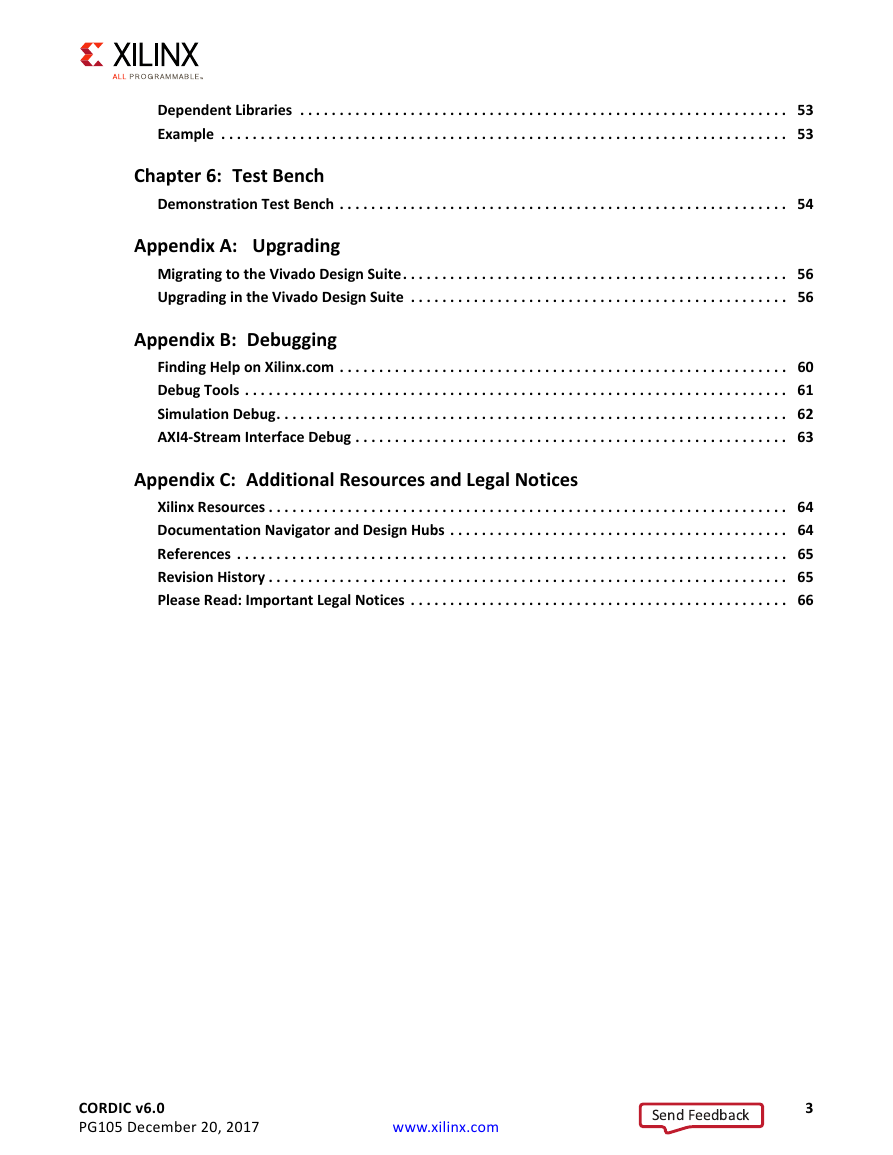
Dependent Libraries . . . . . . . . . . . . . . . . . . . . . . . . . . . . . . . . . . . . . . . . . . . . . . . . . . . . . . . . . . . . . . 53 Example . . . . . . . . . . . . . . . . . . . . . . . . . . . . . . . . . . . . . . . . . . . . . . . . . . . . . . . . . . . . . . . . . . . . . . . . 53 Chapter 6: Test Bench Demonstration Test Bench . . . . . . . . . . . . . . . . . . . . . . . . . . . . . . . . . . . . . . . . . . . . . . . . . . . . . . . . . 54 Appendix A: Upgrading Migrating to the Vivado Design Suite. . . . . . . . . . . . . . . . . . . . . . . . . . . . . . . . . . . . . . . . . . . . . . . . . 56 Upgrading in the Vivado Design Suite . . . . . . . . . . . . . . . . . . . . . . . . . . . . . . . . . . . . . . . . . . . . . . . . 56 Appendix B: Debugging Finding Help on Xilinx.com . . . . . . . . . . . . . . . . . . . . . . . . . . . . . . . . . . . . . . . . . . . . . . . . . . . . . . . . . 60 Debug Tools . . . . . . . . . . . . . . . . . . . . . . . . . . . . . . . . . . . . . . . . . . . . . . . . . . . . . . . . . . . . . . . . . . . . . 61 Simulation Debug. . . . . . . . . . . . . . . . . . . . . . . . . . . . . . . . . . . . . . . . . . . . . . . . . . . . . . . . . . . . . . . . . 62 AXI4-Stream Interface Debug . . . . . . . . . . . . . . . . . . . . . . . . . . . . . . . . . . . . . . . . . . . . . . . . . . . . . . . 63 Appendix C: Additional Resources and Legal Notices Xilinx Resources . . . . . . . . . . . . . . . . . . . . . . . . . . . . . . . . . . . . . . . . . . . . . . . . . . . . . . . . . . . . . . . . . . 64 Documentation Navigator and Design Hubs . . . . . . . . . . . . . . . . . . . . . . . . . . . . . . . . . . . . . . . . . . . 64 References . . . . . . . . . . . . . . . . . . . . . . . . . . . . . . . . . . . . . . . . . . . . . . . . . . . . . . . . . . . . . . . . . . . . . . 65 Revision History . . . . . . . . . . . . . . . . . . . . . . . . . . . . . . . . . . . . . . . . . . . . . . . . . . . . . . . . . . . . . . . . . . 65 Please Read: Important Legal Notices . . . . . . . . . . . . . . . . . . . . . . . . . . . . . . . . . . . . . . . . . . . . . . . . 66 CORDIC v6.0 PG105 December 20, 2017 www.xilinx.com 3 Send Feedback
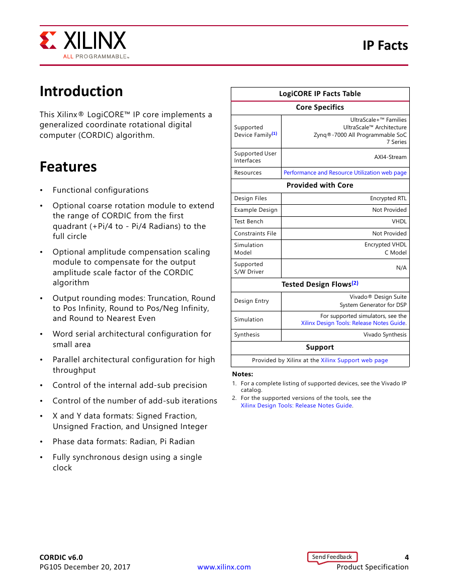
IP Facts LogiCORE IP Facts Table Core Specifics UltraScale+™ Families UltraScale™ Architecture Zynq®-7000 All Programmable SoC 7 Series AXI4-Stream Performance and Resource Utilization web page Provided with Core Encrypted RTL Not Provided VHDL Not Provided Encrypted VHDL C Model N/A Tested Design Flows(2) Vivado® Design Suite System Generator for DSP For supported simulators, see the Xilinx Design Tools: Release Notes Guide. Vivado Synthesis Support Supported Device Family(1) Supported User Interfaces Resources Design Files Example Design Test Bench Constraints File Simulation Model Supported S/W Driver Design Entry Simulation Synthesis Provided by Xilinx at the Xilinx Support web page Notes: 1. For a complete listing of supported devices, see the Vivado IP catalog. 2. For the supported versions of the tools, see the Xilinx Design Tools: Release Notes Guide. Introduction This Xilinx® LogiCORE™ IP core implements a generalized coordinate rotational digital computer (CORDIC) algorithm. Features • • Optional coarse rotation module to extend Functional configurations the range of CORDIC from the first quadrant (+Pi/4 to - Pi/4 Radians) to the full circle • Optional amplitude compensation scaling module to compensate for the output amplitude scale factor of the CORDIC algorithm • Output rounding modes: Truncation, Round to Pos Infinity, Round to Pos/Neg Infinity, and Round to Nearest Even • Word serial architectural configuration for small area Parallel architectural configuration for high throughput • • Control of the internal add-sub precision • Control of the number of add-sub iterations • X and Y data formats: Signed Fraction, Unsigned Fraction, and Unsigned Integer Phase data formats: Radian, Pi Radian Fully synchronous design using a single clock • • CORDIC v6.0 PG105 December 20, 2017 www.xilinx.com 4 Product Specification Send Feedback
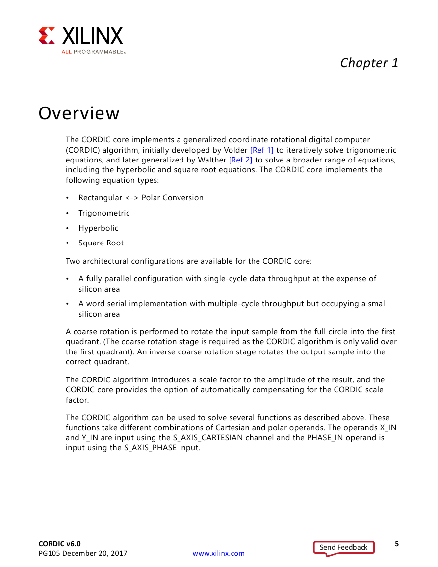
Overview Chapter 1 Rectangular <-> Polar Conversion Trigonometric The CORDIC core implements a generalized coordinate rotational digital computer (CORDIC) algorithm, initially developed by Volder [Ref 1] to iteratively solve trigonometric equations, and later generalized by Walther [Ref 2] to solve a broader range of equations, including the hyperbolic and square root equations. The CORDIC core implements the following equation types: • • • Hyperbolic • Two architectural configurations are available for the CORDIC core: • A fully parallel configuration with single-cycle data throughput at the expense of Square Root silicon area • A word serial implementation with multiple-cycle throughput but occupying a small silicon area A coarse rotation is performed to rotate the input sample from the full circle into the first quadrant. (The coarse rotation stage is required as the CORDIC algorithm is only valid over the first quadrant). An inverse coarse rotation stage rotates the output sample into the correct quadrant. The CORDIC algorithm introduces a scale factor to the amplitude of the result, and the CORDIC core provides the option of automatically compensating for the CORDIC scale factor. The CORDIC algorithm can be used to solve several functions as described above. These functions take different combinations of Cartesian and polar operands. The operands X_IN and Y_IN are input using the S_AXIS_CARTESIAN channel and the PHASE_IN operand is input using the S_AXIS_PHASE input. CORDIC v6.0 PG105 December 20, 2017 www.xilinx.com 5 Send Feedback
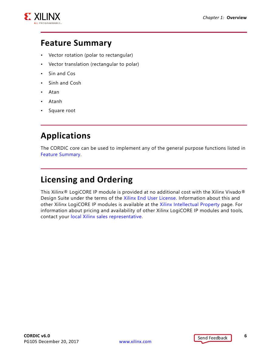
Chapter 1: Overview Feature Summary • Vector rotation (polar to rectangular) • Vector translation (rectangular to polar) • • • Atan • Atanh • Sin and Cos Sinh and Cosh Square root Applications The CORDIC core can be used to implement any of the general purpose functions listed in Feature Summary. Licensing and Ordering This Xilinx® LogiCORE IP module is provided at no additional cost with the Xilinx Vivado® Design Suite under the terms of the Xilinx End User License. Information about this and other Xilinx LogiCORE IP modules is available at the Xilinx Intellectual Property page. For information about pricing and availability of other Xilinx LogiCORE IP modules and tools, contact your local Xilinx sales representative. CORDIC v6.0 PG105 December 20, 2017 www.xilinx.com 6 Send Feedback
Chapter 2 Product Specification The equations used to define the CORDIC are detailed in Functional Description in Chapter 3. Performance The latency and throughput of the core is influenced by the selection of Parallel or Serial Architecture. The resulting basic latency and throughput are described in Parallel Architectural Configuration and Word Serial Architectural Configuration, though it should be noted that latency is affected by the form of AXI4-Stream protocol selected. The CORDIC user interface in the Vivado® Integrated Design Environment (IDE) shows the latency for the selected configuration. It should be stated that when AXI blocking mode is selected, latency should not be a primary design consideration, because the AXI protocol manages data traffic dynamically. Two architectural configurations are available for the CORDIC core: • Parallel, with single-cycle data throughput and large silicon area • Word Serial, with multiple-cycle throughput and a smaller silicon area. This choice is independent of choices relating to AXI4-Stream behavior. Parallel Architectural Configuration The CORDIC algorithm requires approximately one shift-addsub operation for each bit of accuracy. A CORDIC core with a parallel architectural configuration implements these shift-addsub operations in parallel using an array of shift-addsub stages. A parallel CORDIC core with N bit output width has a latency of N cycles and produces a new output every cycle. The implementation size of this parallel circuit is directly proportional to the internal precision times the number of iterations. Word Serial Architectural Configuration The CORDIC algorithm requires approximately one shift-addsub operation for each bit of accuracy. A CORDIC core implemented with the word serial architectural configuration, CORDIC v6.0 PG105 December 20, 2017 www.xilinx.com 7 Send Feedback
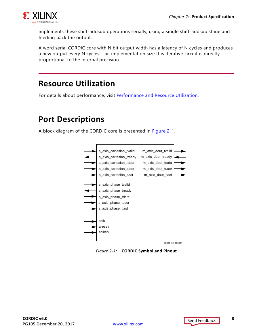
Chapter 2: Product Specification implements these shift-addsub operations serially, using a single shift-addsub stage and feeding back the output. A word serial CORDIC core with N bit output width has a latency of N cycles and produces a new output every N cycles. The implementation size this iterative circuit is directly proportional to the internal precision. Resource Utilization For details about performance, visit Performance and Resource Utilization. Port Descriptions A block diagram of the CORDIC core is presented in Figure 2-1. X-Ref Target - Figure 2-1 Figure 2‐1: CORDIC Symbol and Pinout CORDIC v6.0 PG105 December 20, 2017 www.xilinx.com 8 Send Feedback
分享到:
收藏