Technical Paper of
High-Power Charger for Electric Vehicles
for CHAdeMO 3.0 / ChaoJi type 2
CH/\deMO
24th April, 2020
High Power SWG, CHAdeMO Association
This document contains information that is confidential to the CHAdeMO Association and/or other
companies. It is forbidden to use the contents of this document for anything other than their intended
purpose and/or to disclose or release the documents to a third party without the permission of the
Association.
CHAdeMO Association
�
,
ject between China Electricity Council
mt& meaning 'super' in Chinese), is the codename of the joint pro
Preface
ChaoJi (
(CEC) and CHAdeMO Association for the development of the next generation, ultra-fast EV charging standard.
This document describes some basic specification of ChaoJi-2 standard for the purpose of providing the technical
information to CHAdeMO regular members.
There are currently three types of ChaoJi; type 1 (ChaoJi-1), type 2 (ChaoJi-2) and type 3 (ChaoJi-3).
ChaoJi-1 uses the modified GB/T 27930 CAN protocol (SAE J1939).
ChaoJi-2 uses the CHAdeMO 3.0 CAN protocol (ISO 11898) as defined in this specification.
ChaoJi-3 uses the ISO 15118 protocol and adds a PLC controller to the ChaoJi sequence circuit.
All three types will adopt the same charging connector, vehicle inlet, sequence circuit and charging sequence, and
all the ChaoJi vehicles can have backward compatibility with the existing GB/T, CHAdeMO and CCS-1/-2 chargers
and V2X equipment via the dedicated inlet adapters for each system.
A unified communication protocol for the three ChaoJi types is currently under development.
Specification
Relevant clauses in CHAdeMO 2.x are indicated by [-].
All requirements in CHAdeMO 2.x are valid, except as follows.
1. General requirements
[4.1 (2), CHAdeMO 2.x]
Replacement:
Table 1.1 Output performance
Output voltage range
Output current range
Output power range
1500Vdc
150
1500Vdc (Optional)
50
0
0
600Adc
900kW
NOTE: All the maximum power, voltage and current values in CHAdeMO 2.x are to be replaced accordingly, unless
otherwise defined in this specification.
1.1 Insulation performance
[4.2 (7), CHAdeMO 2.x]
Replacement & addition:
The requirements for charger and vehicle are defined in Table 1.2 and 1.3 respectively. In addition, the charger
shall reduce the output impulse voltage which may be applied to vehicle to less than or equal to 2500V.
Table 1.2 List of insulation performance for charger
Item
Input circuit Output circuit
Input circuit SELV(1)
Output circuit SELV(1)
Input circuit Protective conductor
Output circuit Protective earthing conductor
Insulation performance
Double insulation or Reinforced insulation
Double insulation or Reinforced insulation
Double insulation or Reinforced insulation(2)
Basic insulation
Double insulation or Reinforced insulation(2)(4)
Table 1.3 List of insulation performance for vehicle
Item
Insulation performance
The on-board section of vehicle power supply circuit
according to ISO 17409 Ed.2 (2020)
"Alternative protection measures" according to ISO
6469-3:2018, 6.3.5 shall be applied(2)(3)(4)
CHAdeMO Association Confidential 24th April, 2020
2
�
Safety Extra Low Voltage.
(1)
(2) Basic insulation may be applied for components which are difficult to achieve double or reinforced insulation
e.g. voltage sensor, contactor, under the responsibility of charger and vehicle manufacturers. In such case, the
manufacturers should perform an FMEA and implement additional means or touch voltage/current/energy
limitations to mitigate the risk of hazards to ordinary person (if any) under the single fault condition.
(3) Different measures may be used for different sections of a circuit.
For example;
- High-voltage components (e.g. 12V DC/DC converter, traction inverter) and bus-
bars can apply "conductive
-3, 6.3.5).
protective enclosure with equipotential bonding" in addition to basic insulation (reference: 1S06469
- High-voltage cable assemblies (including the attached connectors) can apply double or reinforced insulation.
(4) Double or reinforced insulation between the output circuit and the protective earthing conductor is only
needed for parts of the circuit that have a working voltage higher than 600Vdc and/or the maximum DC
output voltage (tentative, to be aligned with IEC 61851-23 Ed.2 IS).
2. Connector body
[4.4.1.1. Connector body, CHAdeMO 2.x]
Replacement:
The new ChaoJi connector and inlet shall be applied. The mating section of the connector shall have latch holes,
and the latch holding of the connector shall be performed by the vehicle inlet.
Pin assignment and terminal name of the charging connector are defined in Figure 2.1 and Table 2.1 respectively.
Intersection viewed from the vehicle inlet
3D view of the mating section, showing the position of the latch and drain holes
Figure 2.1
CHAdeMO Association Confidential 24th April, 2020
3
�
Pin number
1
2
3
4
5
6
7
Table 2.1 Terminal name and pin assignment of charging connector
Terminal name
DC output P
DC output N
CHAdeMO 2.x equivalent
DC output P
DC output N
Protective conductor
Protective conductor
S+
S-
CC2
CC1
CAN
CAN
High
Low
Connector proximity detection
Charge sequence signal 1 /
Vehicle charge permission
.
"Charge sequence signal 1"
Visual indication (e.g. lamp) and emergency release of latch holding state by the vehicle inlet are both optional.
NOTE: "Charge sequence signal 2" and "Vehicle charge permission" from CHAdeMO2.x have been deleted and
combined into
The following clauses (including sub-clauses) in CHAdeMO 2.x shall not be applicable: 4.4.3, 4.4.4, 4.4.5.1 and
4.4.5.2.
2.1 Overload current protection and coordination
[4.4.5.1, CHAdeMO 2.x]
Replacement:
The charger and/or the cable assembly shall have a means to protect the charging cable against overload current
and short-circuit current by using a device such as current-limiting fuse. The protective means shall endure, and
protect the charging cable from, P-N short-circuit currents up to 30kA lasting for 2ms at the vehicle inlet. It is
recommended that the overload current protection device is fast acting to mitigate the risk of EV contactor welding
and arcing at the contacts of the charging connector/inlet due to the short-circuit current.
The vehicle shall limit the maximum peak current flowing from the vehicle to 30kA or less accordingly in the event
of P-N short circuit at the vehicle inlet, as per ISO 17409 Ed.2 (2020).
3. Circuit configuration
[6.1, CHAdeMO 2.x]
Replacement:
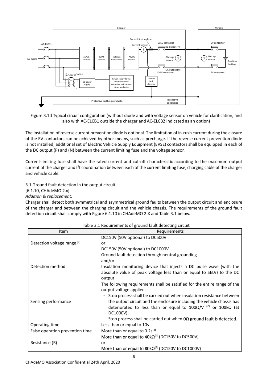
Charger shall comply with the following requirements. Typical circuit configurations are shown in Figure 3.1a, 3.1b,
3.1c and 3.1d.
CHAdeMO Association Confidential 24th April, 2020
4
�
AC-ELCB1
Charger
Vehicle
Reverse current prevention diode
Current limiting fuse
Current sensor
A
EV contactor
DC output (P)
AC mains
--+-+---1,__--o
,.--..
AC/DC
rectifier
DC/AC
inverter
Isolation
transformer
AC/DC
rectifier
Voltage
sensor
V
-+--1----1---n,.--..
AC-ELCB2
DC power
supply
Power supply to the
communications
controller, vehicle and
other auxiliaries
Ground
fault
detector
DC output (N)
Traction
battery
EV contactor
Protective earthing conductor
Protective
conductor
Figure 3.1a Typical circuit configuration (with diode and AC-ELCBs inside the charger)
Charger
Vehicle
Reverse current prevention diode
AC-ELCB1
,,.-..,
---0
AC mains
,..-..,.
---0
V
,,.-..,
---0
1
Current limiting fuse
Current sensor
-Q \
A
.\.
~9
V
Voltage
sensor
DC output (P)
DC output (N)
EV contactor
=
V 7_
:==o--1
Traction
battery
EV contactor
AC-ELCB2 option
~EE
: ~ :
\
;'
AC/DC
rectifier
DC/AC
inverter
Isolation
transformer
AC/DC
rectifier
DC power
supply
I
Power supply to the
communications
controller, vehicle and
other auxiliaries
I
I
Protective earthingconductor
I
I
Ground
fault
detector
I
I
Protective
conductor
Figure 3.1b Typical circuit configuration (with diode, AC-ELCB1 outside the charger and AC-ELCB2 indicated as
an option)
At:..maru,-+--+--+-
-<>
Figure 3.1c Typical circuit configuration (without diode and with voltage sensor on vehicle for clarification)
CHAdeMO Association Confidential 24th April, 2020
5
�
AC-ELCB1
,,......._
---0 a - - -+ - - - - -<
Charger
Current limiting fuse
Current sensor
A
EVSE contactor
DC output (P)
Vehicle
EV contactor
,,......._
---0 o-+-+-....-------l
AC mains
AC/DC
rectifier
DC/AC
inverter
Isolation
transformer
AC/DC
rectifier
AC-ELCB2
option
DC power
supply
Power supply to the
communications
controller, vehicle and
other auxiliaries
Ground
fault
detector
Voltage
sensor
V
V
Voltage
sensor
Traction
battery
DC output (N)
EVSE contactor
EV contactor
Protective earthing conductor
Protective
conductor
Figure 3.1d Typical circuit configuration (without diode and with voltage sensor on vehicle for clarification, and
also with AC-ELCB1 outside the charger and AC-ELCB2 indicated as an option)
The installation of reverse current prevention diode is optional. The limitation of in-rush current during the closure
of the EV contactors can be achieved by other means, such as precharge. If the reverse current prevention diode
is not installed, additional set of Electric Vehicle Supply Equipment (EVSE) contactors shall be equipped in each of
the DC output (P) and (N) between the current limiting fuse and the voltage sensor.
Current-limiting fuse shall have the rated current and cut-off characteristic according to the maximum output
current of the charger and I2t coordination between each of the current limiting fuse, charging cable of the charger
and vehicle cable.
3.1 Ground fault detection in the output circuit
[6.1.10, CHAdeMO 2.x]
Addition & replacement:
Charger shall detect both symmetrical and asymmetrical ground faults between the output circuit and enclosure
of the charger and between the charging circuit and the vehicle chassis. The requirements of the ground fault
detection circuit shall comply with Figure 6.1.10 in CHAdeMO 2.X and Table 3.1 below.
Table 3.1 Requirements of ground fault detecting circuit
Item
Requirements
Detection voltage range (1)
Detection method
Sensing performance
Operating time
False operation prevention time
Resistance (R)
DC150V (50V optional) to DC500V
or
DC150V (50V optional) to DC1000V
Ground fault detection through neutral grounding
and/or
Insulation monitoring device that injects a DC pulse wave (with the
absolute value of peak voltage less than or equal to SELV) to the DC
output
The following requirements shall be satisfied for the entire range of the
output voltage applied.
- Stop process shall be carried out when insulation resistance between
the output circuit and the enclosure including the vehicle chassis has
deteriorated to less than or equal to
or l00kO (at
DC1000V).
100O/V
(2)
00 ground fault is detected.
- Stop process shall be carried out when
Less than or equal to 10s
More than or equal to 0.2s(3)
More than or equal to 40kO
or
More than or equal to 80kO
(4) (DC150V to DC500V)
(4) (DC150V to DC1000V)
CHAdeMO Association Confidential 24th April, 2020
6
�
When the operation voltage is less than GOV, the criteria of 100O/V can be excluded.
(1) Detection voltage range shall comply with the output range of charger.
(2)
(3) The purpose is to prevent a malfunction due to short-term noise current.
(4) The resistors shall be installed to limit the maximum ground fault current to 12.5mA.
3.2 Impedance requirements for charger
[6.1.14 (2), CHAdeMO 2.x]
Replacement:
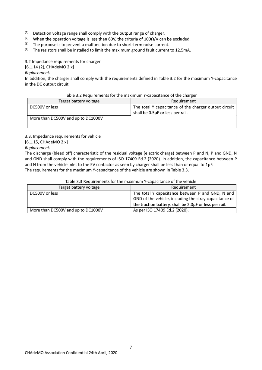
In addition, the charger shall comply with the requirements defined in Table 3.2 for the maximum Y-capacitance
in the DC output circuit.
Table 3.2 Requirements for the maximum Y-capacitance of the charger
Requirement
Target battery voltage
DC500V or less
More than DC500V and up to DC1000V
The total Y capacitance of the charger output circuit
shall be 0.SµF or less per rail.
3.3. Impedance requirements for vehicle
[6.1.15, CHAdeMO 2.x]
Replacement:
The discharge (bleed off) characteristic of the residual voltage (electric charge) between P and N, P and GND, N
and GND shall comply with the requirements of ISO 17409 Ed.2 (2020). In addition, the capacitance between P
and N from the vehicle inlet to the EV contactor as seen by charger shall be less than or equal to
The requirements for the maximum Y-capacitance of the vehicle are shown in Table 3.3.
lµF.
Table 3.3 Requirements for the maximum Y-capacitance of the vehicle
Requirement
Target battery voltage
DC500V or less
More than DC500V and up to DC1000V
The total Y capacitance between P and GND, N and
GND of the vehicle, including the stray capacitance of
the traction battery, shall be 2.0µF or less per rail.
As per ISO 17409 Ed.2 (2020).
CHAdeMO Association Confidential 24th April, 2020
7
�
4. Sequence (control pilot) circuit
[6.2, CHAdeMO 2.x]
Replacement:
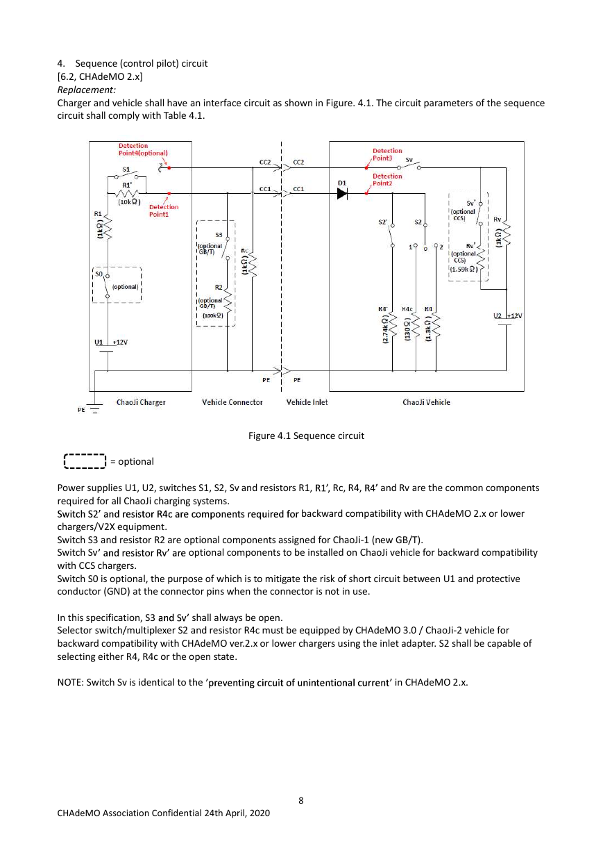
Charger and vehicle shall have an interface circuit as shown in Figure. 4.1. The circuit parameters of the sequence
circuit shall comply with Table 4.1.
Detection
Point4{opt ional]
\
3-;:
Rl'
(10kQJ
I .
Dete ct ,011
Point1
R1
.,,
0:
:!
1so - - - - )
I
(optional) :
I
I
I
I
I
U1
+12V
CC2
CC2
I
I
> CC1
~
Dete ct ion
Poinl3
Sv
D1
Detect[on
Poinl2
S2'
S2
1
0
2
I
sv'
I
I (optional
I C~I
I
I
I
Rv'
I
I (optional
I CCS)
lj1.59kQJ
I
Rv
..,
0:
...
R4'
..
0:
..,
"'
!:!
R4~
..
0:
!!I
R4
...
C:
"'
,<
U2 +12V
Re
0:
.><
:!
r - - - - -
I
S3
I
1[optional
I GB/Tl
I
I
I
I
I
I
1!optional
I GB/Tl
I
(lDOkQ]
L ___
Chaoli Charger
Veh icle Connector
Ve hicle Inlet
ChaoJi Vehicle
PE
PE
PE
Figure 4.1 Sequence circuit
Rl',
I
' and resistor Rv' are
Rc, R4,
R4'
and Rv are the common components
optional components to be installed on ChaoJi vehicle for backward compatibility
backward compatibility with CHAdeMO 2.x or lower
,------,
..., _____ _
= optional
I
Power supplies U1, U2, switches S1, S2, Sv and resistors R1,
required for all ChaoJi charging systems.
Switch S2' and resistor R4c are components required for
chargers/V2X equipment.
Switch S3 and resistor R2 are optional components assigned for ChaoJi-1 (new GB/T).
Switch Sv
with CCS chargers.
Switch S0 is optional, the purpose of which is to mitigate the risk of short circuit between U1 and protective
conductor (GND) at the connector pins when the connector is not in use.
In this specification, S3
Selector switch/multiplexer S2 and resistor R4c must be equipped by CHAdeMO 3.0 / ChaoJi-2 vehicle for
backward compatibility with CHAdeMO ver.2.x or lower chargers using the inlet adapter. S2 shall be capable of
selecting either R4, R4c or the open state.
NOTE: Switch Sv is identical to the
'preventing circuit of unintentional current'
shall always be open.
in CHAdeMO 2.x.
and Sv'
CHAdeMO Association Confidential 24th April, 2020
8
�



 2023年江西萍乡中考道德与法治真题及答案.doc
 2012年重庆南川中考生物真题及答案.doc
 2013年江西师范大学地理学综合及文艺理论基础考研真题.doc
 2020年四川甘孜小升初语文真题及答案I卷.doc
 2020年注册岩土工程师专业基础考试真题及答案.doc
 2023-2024学年福建省厦门市九年级上学期数学月考试题及答案.doc
 2021-2022学年辽宁省沈阳市大东区九年级上学期语文期末试题及答案.doc
 2022-2023学年北京东城区初三第一学期物理期末试卷及答案.doc
 2018上半年江西教师资格初中地理学科知识与教学能力真题及答案.doc
 2012年河北国家公务员申论考试真题及答案-省级.doc
 2020-2021学年江苏省扬州市江都区邵樊片九年级上学期数学第一次质量检测试题及答案.doc
 2022下半年黑龙江教师资格证中学综合素质真题及答案.doc